
A FRAMEWORK BASED ON A HIGH CONCEPTION LEVEL TO
GENERATE CONFIGURATIONS IN PRODUCTION SYSTEMS
Marwa Kanso, Pascal Berruet and Jean-Luc Philippe
Lab-STICC, UBS Saint Maude, Lorient, France
Keywords:
Reconfigurable manufacturing systems (RMSs), Model Engineering, Scheduling, Configuration, Recovery &
reconfiguration.
Abstract:
In this paper, a framework is presented to generate configurations in reconfigurable manufacturing systems
(RMS). This framework is based on a high conception level of reconfigurable manufacturing systems, and uses
a multicriteria decision algorithm to select operations to carry out the request. Provisional product scheduling
is then used to define the “simple configuration”. This paper focuses on the generation process of the “near-
most appropriate” configuration to carry out a request. To do so, the same multicriteria decision algorithm
is used to select “reserved operations” to improve the generated configuration.A case of study illustrates our
approach and demonstrates how we can use this framework to generate the “near-optimal” configuration and
improve reconfigurability.
1 INTRODUCTION
Manufacturing flexibility is the key for markets facing
increasing client demands, frequent volume changes
and product requirement. In such a system, choices
at the system organization level can be delayed un-
til exploitation. Indeed, this organization must be
taken into account at the conception level. To help
a designer choose (resources, operations, ...), a set of
analysis and evaluations must be applied to the sys-
tem. The system description must specify all possible
information for this analysis. New scheduling tech-
niques which help to answer more complex demands
are needed. On the other hand, the main goal in to-
day’s markets is the reaction of manufacturing sys-
tems when unexpected events occur. Recently, new
ideas related to design, description, sequencing prod-
ucts, planning, loading and scheduling policies have
been introduced. Architecture design for manufactur-
ing systems, equiped with the correct level of flexi-
bility to face the specific production problem, are in-
troduced in (Nucci and Grieco, 2008) and in (Terkaj
et al., 2009). (Kurnaz et al., 2005) considers that the
order in which products are produced can have a con-
siderable impact on primary performancemetrics. Se-
quencing decisions can impact customer responsive-
ness. In (Dpto et al., 2002), loading and schedul-
ing processes evolves jointly in Felxible Manufactur-
ing Cell (FMC). (Lamotte, 2006) proposes DeSyRe,
a language to describe reconfigurable manufacturing
systems. In this paper, we propose improving the
DeSyRe language to take into account and improve
the reconfiguration concept at the description level.
We also consider how disruptions (machine break-
downs, customer order changes, etc.) impact the gen-
erated configuration in a reconfigurable manufactur-
ing system producing multiple products. The rest of
this paper is organized as follows. Section 2 gives an
extended presentation of the high conception level of
RMS’s. Section 3 presents the configuration gener-
ation process. A use case illustrates the use of our
framework in section 4, before moving on to the con-
clusion in section 5.
2 A HIGH CONCEPTION LEVEL
FOR RMS
Manufacturing systems can generally be described
from multiple levels of granularity. Fractal manufac-
turing systems (Ryu et al., 2003) takes into account
this granularity by using a multi-level representation.
To represent and manipulate reconfigurable manu-
facturing system concepts, we use a description lan-
guage called “DeSyRe” basically developed and in-
troduced by (Lamotte, 2006). Metamodels show re-
lations between different aspects of a RMS. Models
244
Kanso M., Berruet P. and Philippe J. (2010).
A FRAMEWORK BASED ON A HIGH CONCEPTION LEVEL TO GENERATE CONFIGURATIONS IN PRODUCTION SYSTEMS.
In Proceedings of the 7th International Conference on Informatics in Control, Automation and Robotics, pages 244-248
DOI: 10.5220/0002943102440248
Copyright
c
SciTePress
combine a horizontal decomposition between archi-
tecture and configuration and a vertical one between
logical and physical descriptions. We apply this high
level conception to add new dynamic aspects and im-
prove the RMS description. In the next subsections,
we present the extended description language version
“DeSyRe E”.
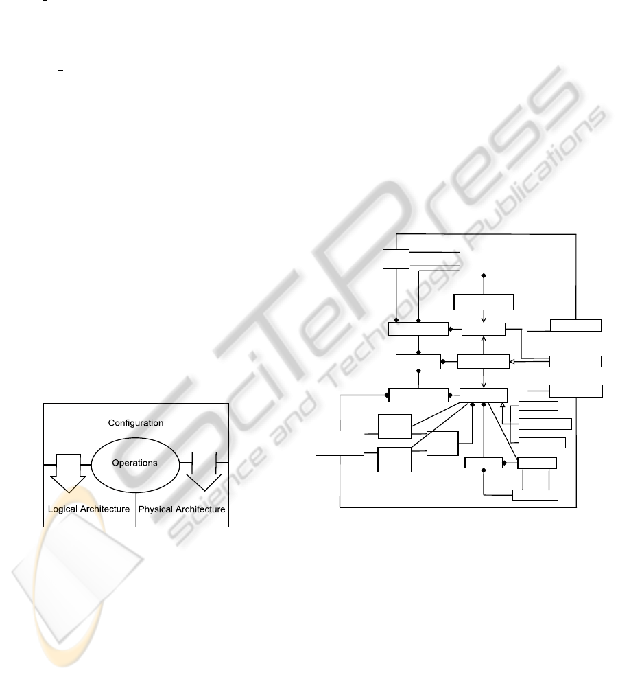
2.1 The represented Aspects
In “DeSyRe E”, the reconfigurable system is broken
down according to the decomposition illustrated in
Figure 1. A horizontal axis separates the architec-
ture of the system from its configuration. The archi-
tecture consists of all system elements (functions, or
resources) and their potential connections. It is pre-
sented in section 2.2. These components are parame-
terized and inter-connected through the configuration
presented in section 2.3. The vertical axis separates
the logical architecture from the physical one. The
logical part consists in the functions and their associ-
ations to form logical operating sequences. The phys-
ical part consists in the resources and the transport be-
tween these resources. The physical part provides the
structure on which the logical part is executed. Oper-
ations are in the center of the model description. Each
operation implements a function on a resource creat-
ing a link between the logical and the physical archi-
tecture. It also links the configuration to the architec-
ture since operations are defined in the architecture
and used in the configuration.
Figure 1: The new decomposition of RMSs.
2.2 A Meta-model to represent
Architectures
The architecture of a reconfigurable manufacturing
system should represent all system potentialities (see
figure 2). It is separated into two parts: the log-
ical architecture, which is constituted by functions
and function sequences applied to products that can
be performed on the system, and the physical archi-
tecture which describes the physical elements of the
system (resources, connections, ports, etc...). To
achieve a complete architecture representation, op-
erating modes of the whole system should be pro-
vided. The role of such representation is to help carry
out decisions about resource modes and configuration
changing. A lot of information is needed to manage
resource modes, see (Hamani et al., 2009), and per-
form performance and cost analysis. This information
is introduced using a simple diagram graph for each
resource to describe their modes and transitions be-
tween these modes. For the sake of simplicity, here,
we propose to take into account the following modes:
the mode “stop” when the power is off, the mode “in
production” when the resource is in use, the mode
“in preparation” when the resource is not in use, nor
ready to execute an operation, the mode “break down”
when a failure occurs on the resource and the mode
“idle” when the power is on and the resource is ready
to use.
Logical architecture is mapped onto physical ar-
chitecture through potential operations, which link a
function with a resource.
Architecture
LogicalArchitecture
PhysicalArchitecture
PotentialOperation
Function
PotentialTransfering
Product
Resource
FunctionSequence
ParamatrizedFunction
MachiningResource
StockResource
Port
Mode
DG
Transition
ToPortRef
FromPortRef
[*]
[*]
[*]
[*]
[*]
[0-1]
[0-1]
[*]
[*]
[*]
[*]
[*]
[*]
[*]
[*]
[*]
[*]
[*]
[*]
[*]
Connection
PotentialMachining
PotentialStocking
[*]
[*]
[*]
[*]
TransportResource
Figure 2: Extended architecture metamodel.
2.3 A Meta-model to represent
Configurations
The concept of configurations lay on the separation of
the componentcontent from its use in the architecture.
A configuration is constituted by function instances to
realize a machining operation, connection instances
to realize a transfer operation, operations which re-
fer to an operation defined in the architecture model
and operation sequences which realize a function se-
quence. The metamodel representing the configura-
tion is given in figure 3.
A FRAMEWORK BASED ON A HIGH CONCEPTION LEVEL TO GENERATE CONFIGURATIONS IN
PRODUCTION SYSTEMS
245
Configuration
OperationSequence
FunctionInstance
Operation
MachiningOPeration
StockingOperation
TransferOperation
ConnectionInstance
[0-1]
[0-1]
OperationInSequence
ProductInState
[*]
[*]
[*]
[*]
[*]
[*]
[*]
[*]
Figure 3: Extended configuration metamodel.
Several types of configurations are defined de-
pending on the use of architecture components. A
minimal configuration contains the needed operations
to carry out a mission. A simple configuration is de-
fined as the set of “used” operations which lead to
the completion of a mission. A flexible configuration
is defined by a set of “used” and “reserved” opera-
tions to simplify the reconfigurability aspect. Finally,
a maximal configuration is defined as the set of poten-
tial operations which lead to carrying out a mission.
In the next section we present the Configuration Gen-
eration module.
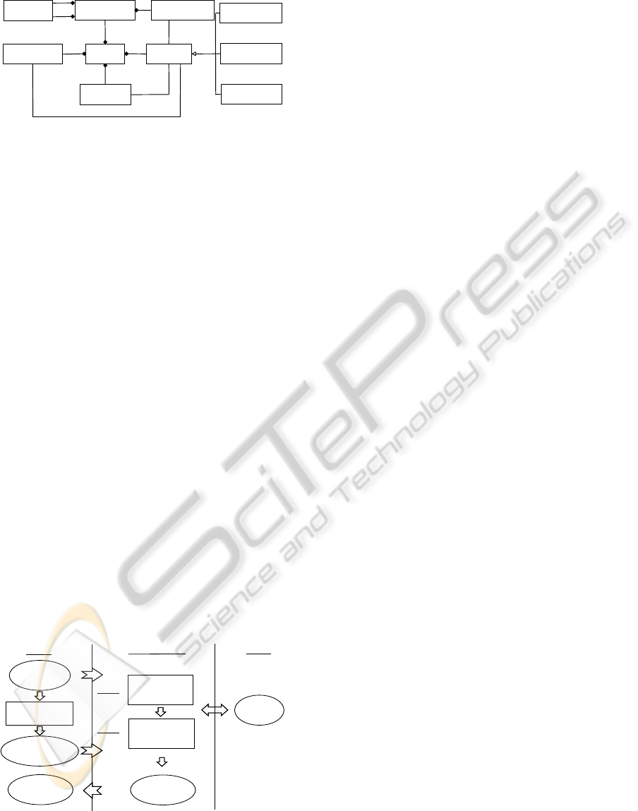
3 CONFIGURATION
GENERATION
As can be seen in the figure 4, three technologies
are used: Model driven engineering (MDE), object
oriented programmation and multiCriteria Decision
Making (MCDM). Modeling concepts are introduced
to describe architectures and configurations. The
Model Driven engineering approach (MDE) is then
used, a transformation module is used to generate the
maximal configuration from the architecture descip-
tion model. This transformation is expressed in a
transformation language such as ATL (B´ezivin et al.,
2005).
Extended
Description Model
(Architecture)
Description Model
(maximal Configuration)
Maximal Configuration
Generator
MDE
Object Oriented
MCDM
AHP Algorithm
Step 1
Step 2
Simple Configuration
Generator
+
Products Scheduling
Flexible Configuration
Generator
+
Products Scheduling
"near-optimal"
Configuration
Description Model
("near-optimal"
Configuration)
Figure 4: A framework to generate configurations.
Generated code is based on the architecture and
maximal configuration description models. Object
oriented development (using Java) is then used to
carry out the “near most-appropriate” configuration.
At runtime, both steps (1 and 2) use the MultiCrite-
ria Decision Making approach (MCDM) to solve in-
determinism due to the high flexibility of our system
and to carry out the request in the configuration. For
more details about the MCDM approach see (Kanso
et al., 2009). A simple configuration is generated in
step 1. The obtained configuration contains only the
“used” operations to carry out the mission. It means
that, in case of failure there is no garantee to replace
the failed operation. Our framework tries to avoid the
reconfiguration process as much as possible, by im-
proving the generated configuration with a compati-
ble degree of flexibility. We deal with two kinds of
unexpected events: changes at the request level (case
of customer demand changes) and changes at the sys-
tem level itself (case of failures and system errors).
When unexpectedevents occur, errors, failures or cus-
tomer demand changes provide the need of additional
operations to replace the failed ones. Operations in
need are evidently defined in the architecture. To an-
swer this need, a flexible configuration is generated in
step 2. This last configuration consists of the simple
configuration improved by adding “reserved” opera-
tions using the MCDM approach. The obtained con-
figuration description model is then generated using
MDE.
4 SAMPLE EXPERIMENTATION
We present, in this section, a simple example to
demonstrate how our frameworkcan be used to gener-
ate the “near optimal” configuration. The purpose of
this experimentation is not to generate optimal sug-
gestions, but rather to provide a simple demonstration
to help users taking their decisions during production.
To do so, we consider a simple reconfigurable man-
ufacturing system with two products. The “logical
architecture” contains two functions (F
1
and F
2
) and
three function sequences (S
1
, S
2
and S
3
). S
1
consists
in implementing F
1
. S
2
consists in implementing F
2
.
S
3
consists in implementing F
1
then F
2
.
The “Physical Architecture” of the proposed sys-
tem is defined to set up our experiments (see figure 5).
It consists of convoyers (CV
1
- CV
6
), buffers (IN and
OUT), machining areas (M
1
- M
4
) and a robot (Rbt
1
).
To increase the flexibility of the system, this archi-
tecture consists of the two-directional convoyers (CV
2
and CV
5
). In the description model of the architec-
ture, we refine, for each resource, its capacity, its ac-
tive mode, the list of the concerned resource modes
and the transitions between these modes.
ICINCO 2010 - 7th International Conference on Informatics in Control, Automation and Robotics
246

Figure 5: Physical Architecture of the proposed system.
Eight machining operations have been defined to
assign the defined functions to the machining areas:
O
M1,F1
, O
M1,F2
, O
M2,F1
and O
M2,F2
, etc...
Fourteen transfer operations have also been de-
fined to realize a transfer using a transfer ressource:
O
t
Cv1,INM1
, O
t
Rbt,INM1
, O
t
Rbt,INM2
, O
t
Cv2,M1M2
, O
t
Cv2,M2M1
,
etc...
4.1 Maximal Configuration Generation
In this subsection, we present the transformation
module used to generate the “maximal configuration”
using the architecture description model. Based on
the specified mission (product types and quantities),
some operations cannot be used in the system. The
concerned resources are idle during production. To
optimise the configuration cost, we must generate the
“maximal configuration”. At this stage, we take into
consideration the system part which contains the pos-
sible operations to carry out the request. If all po-
tential operations can be used to realize our mission,
the maximal configuration represents the use of the
whole system. For reasons of simplicity, in our ex-
ample, the maximal configuration represents the use
of the whole system to carry out two different prod-
uct types (P
4
and P
5
). Each operation in the architec-
ture model is projected to generate an operation in the
configuration model. The link to a function instance
or a connection instance in the configuration model
is based on the type of the operation in the architec-
ture. A function sequence can be realized by different
operation sequences. For example, S
1
is the function
sequence which consists of applying the function F
1
on a product. It can be realized on the machining re-
source M
1
, M
2
, M
3
or on M
4
. These four solutions
are defined in the configuration model as a set of 88
operation sequences, since transfer may be realized
by different transfer sequences too. Indeed, we gen-
erate 674 possible operation sequences based on the
function sequences defined in the architecture model.
It should be noticed that by using all the opera-
tions and operation sequences of the system in the
configuration at runtime, the reconfiguration time, in
case of failure can be shorten (it depends on calcula-
tion and decision making time), and the cost of the
configuration is surely much higher since a lot of re-
sources are idle. Therefore, we propose to generate
the “near-optimal” configuration which answer a bet-
ter cost-performance trade-off. In the next subsection,
we refine the “Simple Configuration generation” pro-
cess based on the architecture and the maximal con-
figuration description models.
4.2 Simple Configuration Generation
The specified mission consists of producing three lots
of P
4
and two lots of P
5
. Decisions, of which trans-
porter (or machining resource) is used, are taken by
applying the ‘AHP’ algorithm. For more details about
the proposed algorithm please check (Kanso et al.,
2009). The “Simple Configuration Generation” pro-
cess consists of selecting, for each product instance,
an operation sequence taken into account the system
state (resource availability, waiting time, preparation
time, mode changes, transfer between two different
machining resources). We use the necessary informa-
tion in the architecture to decide which is the most
appropriate operation to realize next. This process
has been implemented using Java in eclipse environ-
ment. Once the application is launched, the selection
process starts. The architecture of the proposed sys-
tem is updated depending on each resource capacity
and modes in the system while executing an operation
on a product. The “simple configuration” is obtained
when each product instance specifies its operation se-
quence and its provisional scheduling. We define at
this level the “used operation” as an operation used
by a product to realize a function in a configuration.
For the proposed example we get the configuration
composed of the followed operation sequences:
1. to realize P
4
, S
1
must be applied. Therefore, the
operation sequence chosen is as follows:
• OS
1,S
1
: {O
t
Cv1,INM1
, O
M1,F1
, O
t
Rbt,M1OUT
}
2. to realize P
5
, S
3
must be applied. Therefore, the
operation sequence choosed is as follows:
• OS
12,S
3
: {O
t
Cv1,INM1
, O
M1,F1
, O
M1,F2
,
O
t
Rbt,M1OUT
}
4.3 Flexible Configuration Generation
In case of production problems and more precisely
in case of failure when unexpected events occur
(demand changes, resource breakdowns, unavailable
tools, etc...). Previously generated simple configu-
rations may no longer work. Operations used in the
“simple configuration” may be unique and no another
A FRAMEWORK BASED ON A HIGH CONCEPTION LEVEL TO GENERATE CONFIGURATIONS IN
PRODUCTION SYSTEMS
247

operation, defined at the configuration level, can re-
alize the same function. The obvious solution is to
reconfigure the system. Although, we propose to im-
prove the generated configuration and optimise the re-
quest completion time. Therefore, we need to extend
the “simple configuration” and add “reserved opera-
tions”. At this level, we define a “reserved operation”
as an operation chosen to replace a failed operation
in a configuration. This will help us carrying out
the request in the system without going through the
reconfiguration process. To do so, “reserved opera-
tions” are selected using the ‘AHP’ algorithm. When
the “reserved operations” are specified, we generate
the corresponding operation sequences to fill out the
generated configuration. In other words, we generate
reserved operation sequences to extend the obtained
“simple configuration” and get the “flexible configu-
ration” to improve system responsiveness. Projecting
this extension on our example, we get the “flexible
configuration” by duplicating operations since each
function (or transfer) can be realized using four re-
sources (M
1
- M
4
) for a function, and the robot or
a convoyer for a tranfer). We note that in our case
the obtained “flexible configuration” corresponds to
“162” operation sequence of the “maximal configu-
ration” using two machining resources (M
1
and M
2
)
and “used operations” are realized in priority.
5 CONCLUSIONS
Reconfigurable Manufacturing Systems are faced
with frequent disruptions that impact the production
quality. A low-cost solution is needed to recover
the system. In this paper, the use of a high con-
ception level for reconfigurable manufacturing sys-
tems is presented to include different features and de-
scribe both architecture and configuration. The sug-
gested framework produces “near-optimal ” configu-
ration by generating the corresponding “flexible con-
figuration” based on the generated “simple configu-
ration” and the architecture. A simple example illus-
trating the way we can use the proposed framework
is presented in section 4. First, the production envi-
ronment has been presented. Secondly, the “maximal
configuration” generation is presented by refining the
transformation module. Third, the “simple configura-
tion” generation process is described before moving
on to presenting the “flexible configuration” genera-
tion process. Configuration choices usually depend
on preferences, on choices obtained at the scheduling
level, and on constraintes defined by clients at the re-
quest level. “Minimal” and “Simple” configurations
are not always the best solutions. Configurations with
a higher degree of flexibility may respond to requests
with better measures, and may answer a better cost-
performance trade-off. Although the existing frame-
work provides opportunity for many different types
of analyses, additional extensions will be beneficial
as well. These include inventory management during
production and transfer sequence management; new
configuration extension rules; and more specific crite-
ria to improve operation choice. More generally, we
would like to permit a broader class of configurations,
such as serial parallel lines with crossover, so that the
framework can be applied in an even greater number
of circumstances.
ACKNOWLEDGEMENTS
The authors are pleased to acknowledge the sup-
port by the associate professor at Polytech’Marseille
Fouzia Ounnar.
REFERENCES
B´ezivin, J., Jouault, F., Rosenthal, P., and Valduriez, P.
(2005). The AMMA platform support for modeling
in the large and modeling in the small.
Dpto, A. G., Gmez, A., Fuente, D. D. L., Parreo, J., and
Puente, J. (2002). Scheduling in flexible manufactur-
ing systems. Applied Artificial Intelligence, 15:949–
963.
Hamani, N., Dangoumau, N., and Craye, E. (2009). Re-
active mode handling of flexible manufacturing sys-
tems. Mathematics and Computers in Simulation,
79(5):1421–1439.
Kanso, M., Berruet, P., and Philippe, J. (2009). Multi-
criteria decision making approach for reconfigurable
manufacturing systems. In proceeding ISBN of the
28th EAM Conference on Human Decision-Making
and manual Control, SEPT. 3-4, 2009, pages 37–44.
Kurnaz, S., Cohn, A., and Koren, Y. (2005). A frame-
work for evaluating production policies to improve
customer responsiveness.
Lamotte, F. D. (2006). Proposition d’une approche haut
niveau pour la conception, l’analyse et l’implantation
des systmes reconfigurables 2006. PhD thesis. Uni-
versit de Bretagne Sud, Lorient, France.
Nucci, F. and Grieco, A. (2008). The operational strategies
in focused flexible manufacturing systems. ISC’08
International Supercomputer Conference. Heidelberg,
Germany, June 18 20.
Ryu, K., Son, Y., and Jung, M. (2003). Modeling and spec-
ifications of dynamic agents in fractal manufacturing
systems. Comput. Ind., 52(2):161–182.
Terkaj, W., Tolio, T., and Valente, A. (2009). Designing
manufacturing flexibility in dynamic production con-
texts. In Design of Flexible Production Systems, pages
1–18.
ICINCO 2010 - 7th International Conference on Informatics in Control, Automation and Robotics
248
