
A METHOD TO CREATE THE MOST ACCURATE TARGETING
IN 1 ON 1 SOCCER ROBOTS
Yahya Hassan Zadeh Nazarabadi, Hossein Saghlatoon and Mohammad Ali Sharif Shazileh
Parse United Robotics Team, Ferdowsi University, Park Sq, Mashhad, Iran
Keywords: C Programming Language, 1 to 1 Soccer robots, Ultrasound, Compass, Microcontroller.
Abstract: Because the final state of robo soccer is targeting the goal, it’s very important to design and use standard
high accuracy methods. In this paper we discuss about goal targeting and design a method for robo soccer to
target more accurate than the other methods. This method is easier, less complicated and needs less space on
processor flash memory.
1 INTRODUCTION
The main goal of robocup is to, by the year 2050,
develop a team of fully autonomous humanoid
robots that can win against the human world soccer
champion. Up to now, many fields of soccer robot
have been developed such as Humanoid Robots ,
Small & Middel Size Robots , 1 on 1 and 2 by 2
soccer Robots.
This is why soccer robots must be autonamous .
Designing their algorithm is disscused as the most
important aspect.
Therfore a research has been done to design an
optimum and more accurate with the least slip
algorithm for goal targeting in 1 on 1 soccer robots.
In this event, 1 on 1 autonomous mobile robot
team plays in a highly dynamic environment,
tracking a special light-emitting ball in an enclosed,
landmarked field.
In this paper we first define the problem in part
2, in part 3 we have a discussion about method and
materials, in part 4 we introduce the results of
testing this method with a robot , and finally in part
5 we come to a conclusion and give suggestion how
to develop this alghorithm to other kinds of soccer
robot.
2 DEFINING THE PROBLEM
In this section we speak about the problem and use
the global standard rules of 1 on 1soccer robots
made by Robocup organization and used in
international robocups.
Two different kind of fields, named SOCCER A
and SOCCER B, may be used at a tournament.
SOCCER A: The playing-field is 122 cm by 183
cm. The corners are flattened.
SOCCER B: The playing-field is 122 cm by 183
cm. There is an open space of 30 cm width around
the field.
Walls are placed all around the field, including
behind the goals and, if applicable, the open space.
The height of the walls is 14 cm. The walls are
painted matte black.
SOCCER A: The width of each goal is 45 cm,
centered on each of the shorter sides of the playing-
field. The goal is 14 cm high. It has a cross-bar on
top (to prevent robots from entering the goal). The
interior of the goal including floor, walls and cross-
bar painted, one side yellow and the other side blue.
The exterior is painted black.
SOCCER B: The width of each goal is 60 cm,
centerd on each shorter sides of the playing-field.
The goal is 10 cm high. It has a cross-bar on top (to
prevent robots from entering the goal). The interior
of the goal including floor, walls and cross-bar
painted, one side yellow and the other side blue. The
exterior painted black.
The fields should be placed such that the
influence of external infrared light be as low as
possible and the magnetic field of the earth is
disturbed as little as possible. Perfect conditions
cannot be guaranteed, however.
269
Hassan Zadeh Nazarabadi Y., Saghlatoon H. and Ali Sharif Shazileh M. (2010).
A METHOD TO CREATE THE MOST ACCURATE TARGETING IN 1 ON 1 SOCCER ROBOTS.
In Proceedings of the Fifth International Conference on Evaluation of Novel Approaches to Software Engineering, pages 269-272
DOI: 10.5220/0002932102690272
Copyright
c
SciTePress
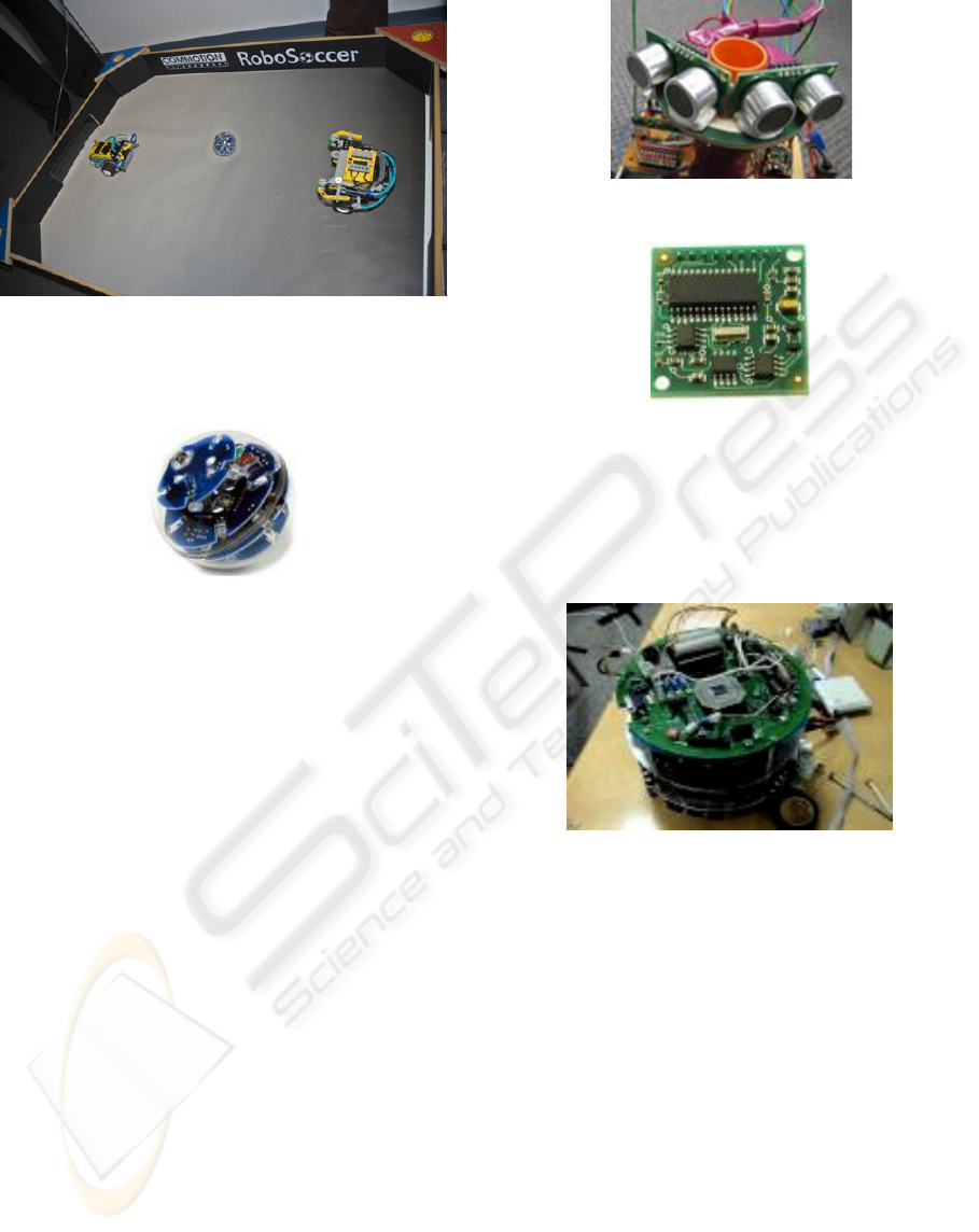
Figure1: A standard Robocup field.
A well-balanced electronic ball shall be used. The
ball will emit infrared (IR) light.
Figure 2: The standard ball with IR Sensors.
So robot should have IR sensors in different vectors
to detect the ball and come to get it.
But the main problem discussed in this paper is
after detecting ball and getting it, How we can detect
the goal and shoot to the goal with high accuracy
and make sure that our robot is in a suitable
situation or not?
3 METHODS AND MATERIALS
In this section we discuss the algorithm we use to
have an accurate goal detecting and shooting.
3.1 Situation Detecting Hardware
First we should define the materials use to detect our
situation. In this research a compilation of spherical
& cubic coordinate is used to locate the situation. So
distance detecting and angle detecting sensors are
needed.
We use ultrasound sensors for distance and apply
a compass sensor to detect angle.
Notice that because of special kind of ball any
IR-based sensor that is used for distance or angle
detection is not accurate enough.
Figure 3: Ultrasound Sensors.
Figure 4: Compass Sensor.
We also need a processor to process the output
signal of these sensors.
Figure 5 shows a soccer robot made by the
author of this paper. This robot has the same
hardware and algorithm.
Figure 5: Soccer robot.
3.2 Situation Detecting Algorithm
To detect the situation we should use our output
signals of sensors and process them.
As default we use 4 sensors in robot, one in each
side of robot (east, west, north and south). Also the
zero degree of angle is shown in figure 6.
In this method robot finds the target with its distance
to the walls of field and its angle. Indisputable for an
accurate shoot, robot should turn to appropriate
angle ratio to goal .since the angle is variable into
the situation, we use the total distance to walls to
find appropriate angle. In this way robot first finds
its situation and then finds the accurate angle for
shooting the ball (shooting angle), then the robot
rotates to the proper angle and shoots the ball.
ENASE 2010 - International Conference on Evaluation of Novel Approaches to Software Engineering
270
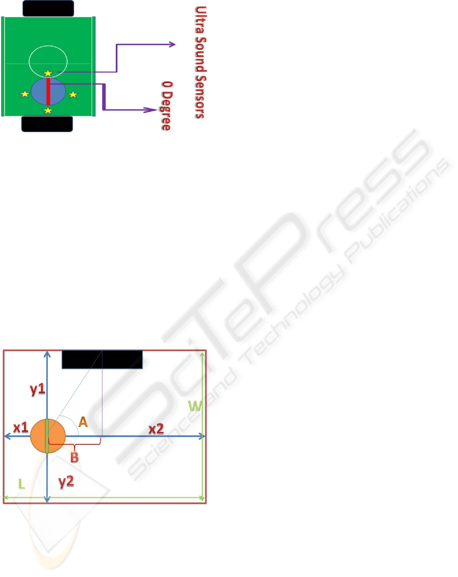
Figure 6: Robot’s Ultra sensor and 0 degree.
3.2.1 Single Situation Detection
In this way , first suppose that just one robot is in the
field, the total distance of robot to the walls in x & y
are constant extent and equal to width and length of
the field. Another alternative is when we calibrating
the robot in the field it defines the front gate as
rival's and the behind as it's own. So according to
figure 6, the angle in attack normally varies between
- 90 degree (right) to +90 degree (left).
To define coordination as shown in figure 7,
robot has 4 numbers to show its coordination.
Variables x1 and x2 are to define coordination in x
vector and variables y1 and y2 are to define
coordination in y vector.
Figure 7: coordination parameters.
The black box is the target and the violet line is
drawn from the center of the target. Another line is
drawn from the center of target to the center of
robot’s shooter device. Angle A is the appropriate
angle for shooting. In other words, if robot rotates
from its 0 to A and then shoots the ball, it will hit the
target.
To calculate the amount of A in this method
robot first should denote whether it's in the
right-half of field or left one. Here is this detection
code in C++ programming language.
Int cor ;
Float x1,x2,B,angle;
if(x1>x2) cor=1;//denote right
else if (x1<x2) cor=2;//denote left
else cor=0;//denote middle
switch (cor) {
case 1:
B=L/2-x1;
Break;
Case 2:
B=L/2-x2;
Break;
Case 0:
B=L/2;
};
After defining the robot area, now it’s the time to
calculate angle A. As shown in figure 7 we suppose
that X2 > X1 so according to upper code cor = 2.
Other supposition are the Length (=L) and
Width (=W) of the field. So as shown in equations
bellow:
B = x1 – (L/2) (1)
A=arctan(y1/B) (2)
According to Figure 6 if x1 > x2 we should
subtracting A to -1 and if x1 < x2 we should subtract
A to 1.
So according to equations (1) and (2) robot can
calculates the amount of angle A.
In other words this method consist of 5 stage:
1) Robot should detect the ball and go to get it.
2) after getting the ball, Robot should turn to its 0
degree.
3) after turning to zero, robot should calculate the
appropriate angle (A) .
4) after calculating the angle, robot should turn to
that angle .
5) shooting and Goal!
A METHOD TO CREATE THE MOST ACCURATE TARGETING IN 1 ON 1 SOCCER ROBOTS
271
3.2.3 Situation Detection in Match
Because in 1 on 1 soccer there are only two robots in
the field, this method suffers some error states that
cause problems for robot .These stages happen when
one robot is sensing by ultrasound sensors at the
time that the other robot wants to shoot. In this
occasion the stricker robot should move to change
its situation. This scape from the last occasion
depends on the robot’s velocity and the clock of
system.
3.2.3.1 How to Detect this Error Situations
As shown in figure 7 we have equations below:
x1+ x2 = L (3)
y1+ y2= W (4)
In fact according to the situation two variables of x1,
x2, y1, y2 are as data and the others are as parity. In
other words, before using this method to notice that
whether robot is in the error state or not, it should
use the equations 3, 4 as provision to continue the
method.
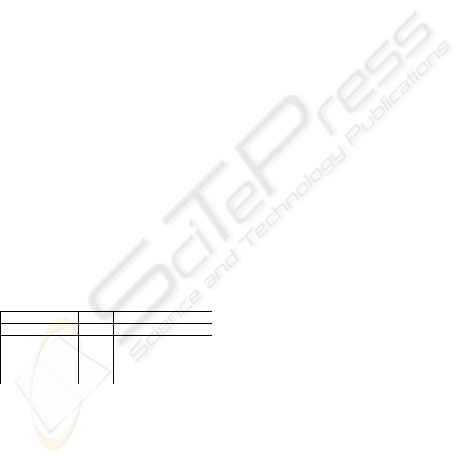
4 RESULTS
This method has been tested with the soccer robot
shown in figure 5. The field was
182 (=L) * 122 (=W). The coordination, targeting
angle and average of accuracy in 100 times of trying
out (20 times for each one) shown in table 1.
Table 1: The results of testing this method with a robot.
Number X1 Y1 Angle Accuracy
1 31.6 59.3 0.772284 100%
2 42.1 96.7 0.601476 100%
3 132.9 100.2 -1.18239 100%
4 91.6 90.2 -1.56969 100%
5 60.0 88.2 1.227777 100%
5 CONCLUSIONS
In this paper we first mooted a problem in targeting
goal in 1 on 1 soccer autonomous robots. Then we
designed a method to have a most accurate targeting.
In this method robot in each situation could
easily finds the appropriate targeting angle to the
center of goal.
By using this method robot has a most accurate
targeting than the other methods. As shown in table -
1 the accuracy of this method for 100 times of trying
out is 100%.
Though this method is designed for 1 on 1 soccer
robots, but it could be used in other soccer robots
like small size or middle size leagues.
REFERENCES
Hassan Zadeh Nazarabadi, Y., Yazdanpanah, N, 2009.
Design the algorithm of deminer autonamos robot. 1
st
National Conferance On Fundamentals Of Software
Engineering, Lahijan, IRAN.
Floyd, 2006. Digital Fundamentals, Pearson Education.
London, 9
nd
edition.
Kaheh Ali, 2009. AVR microcontroler and their
fundamental, NAS, Tehran, 4
th
edition.
ENASE 2010 - International Conference on Evaluation of Novel Approaches to Software Engineering
272
