
USING TASK AND DATA MODELS FOR USER INTERFACE
DECLARATIVE GENERATION
Vi Tran
+
, Manuel Kolp
+
, Jean Vanderdonckt
+
and Yves Wautelet*
+
Louvain School of Management-PRISME, Université catholique de Louvain, Louvain-la-Neuve, Belgium
*Faculteit Economie en Management, Hogeschool-Universiteit Brussel, Brussel, Belgium
Keywords: Task Model, Domain Model, Automatic Generation, User Interface, Agent Software.
Abstract: User interfaces for data systems has been a technical and human interaction research question since a long
time and today these user interfaces require dynamic automation and run-time generation to properly deal
with on a large-scale. This paper proposes a framework, i.e., a methodological process, a meta-model and a
computer software to drive the automatic database user interface design and code behind generation from
both the task model and data model combined together. This includes both the user interface and the sound
and complete data update, definition and manipulation.
1 INTRODUCTION
Database systems have always been a major
component in business-oriented software
applications. To be productive on a day-to-day basis
and used by the organization non-IT staff, these
enterprise complex packages require all to support
and provide for efficient human-computer
interaction (HCI) with the database systems.
From the point of view of final business actors,
these HCI interactions are today managed through
ergonomic database user interfaces (UI).
UI researchers have richly discussed about the
capability and importance of automatic user
interface generation and propose them as the core of
visual-based development environments (Olsen et
al., 1993). There are currently numerous and various
approaches using different input materials: designs,
patterns, architectures, declarative models, …
In this set of techniques, an emerging method is
the automatic UI generation from declarative models
(Puerta et al., 1994; Da Silva et al., 2000;
Schlungbaum and Elwert, 1996; Janssen et al., 1993;
Griths et al., 1999), inspired from Fourth Generation
Languages code generation (Da Silva et al., 2000).
In practice, these models are high-level abstraction
such as goal or task (Paternò et al., 1997),
presentation, dialogue (Janssen et al., 1993),
interaction or domain (Puerta et
al., 1994) models. As
a matter of fact, the agent model, for instance, uses
modeling constructs that are inspired from the
organizational world (actors, goals, beliefs, plans,
intentions, resources, …) and typically serve well as
a human computer interaction medium in software
development including database and UI applications
design. The task model, declarative model typically
used in UI design, records the tasks that potential
end-users of the system may need to perform to do
their jobs, independently of dealing with a particular
computer (Paternò et al., 1997). Much of the design
of an interactive system is generated based on
supporting these tasks.
Another technique, related to declarative models,
is to use the data model of or engineered from the
database itself. For instance, (object-)relational data
models can be effectively used to generate the
database application interfaces (Puerta et al., 1994;
de Baar et al., 1992). Unfortunately this method only
generates static UI layouts and fails to apprehend the
dynamic features that operate on the database.
Moreover, automatically generated database
applications user interfaces poorly manipulate data
as a combination of simple widgets such as lists and
forms. Typical examples are forms for search
criteria and data detail with buttons to validate or
cancel operations and transactions, list for table
results with display and manipulation buttons for
adding/editing/deleting, data (Moroney and
MacDonald, 2006).
155
Tran V., Kolp M., Vanderdonckt J. and Wautelet Y. (2010).
USING TASK AND DATA MODELS FOR USER INTERFACE DECLARATIVE GENERATION.
In Proceedings of the 12th International Conference on Enterprise Information Systems - Human-Computer Interaction, pages 155-160
DOI: 10.5220/0002901501550160
Copyright
c
SciTePress
This research proposes a framework, i.e., a
methodological process, a meta-model and a
computer software to drive the automatic database
user interface design and code behind generation
from both the task model and data model combined
together. This includes both the user interface and
the sound and complete data update, definition and
manipulation (inserting a record, updating a record,
deleting a record ...)
Our framework is based and supported by
declarative technologies we have pointed out above.
More specifically, we will adopt the agent paradigm
(models, language, methods, …) to analyze task and
data models and generate the database UI
specifications and application code.
The rest of this paper is organized as follows: we
present in Section 2 our automatic UI and code
generation process taken together the task and data
models. Section 3 explains the roles of the main
concepts (agents and plans) that participate in this
process such as the query analyzer, the UI designer,
the code generator for both the data reviewing and
editing. Finally, we propose some conclusions.
2 ENGINEERING UI FROM DATA
AND TASK MODELS
According to the Unified Process adapted for UI
design, the practical working process one can do
from getting the requirement to implementing the UI
application has to analyze the requirement specs,
specify the (object or agent) structural and
operational models at the conceptual and logical
levels, select the layout platform, design the user
interface … and finally perform the UI design.
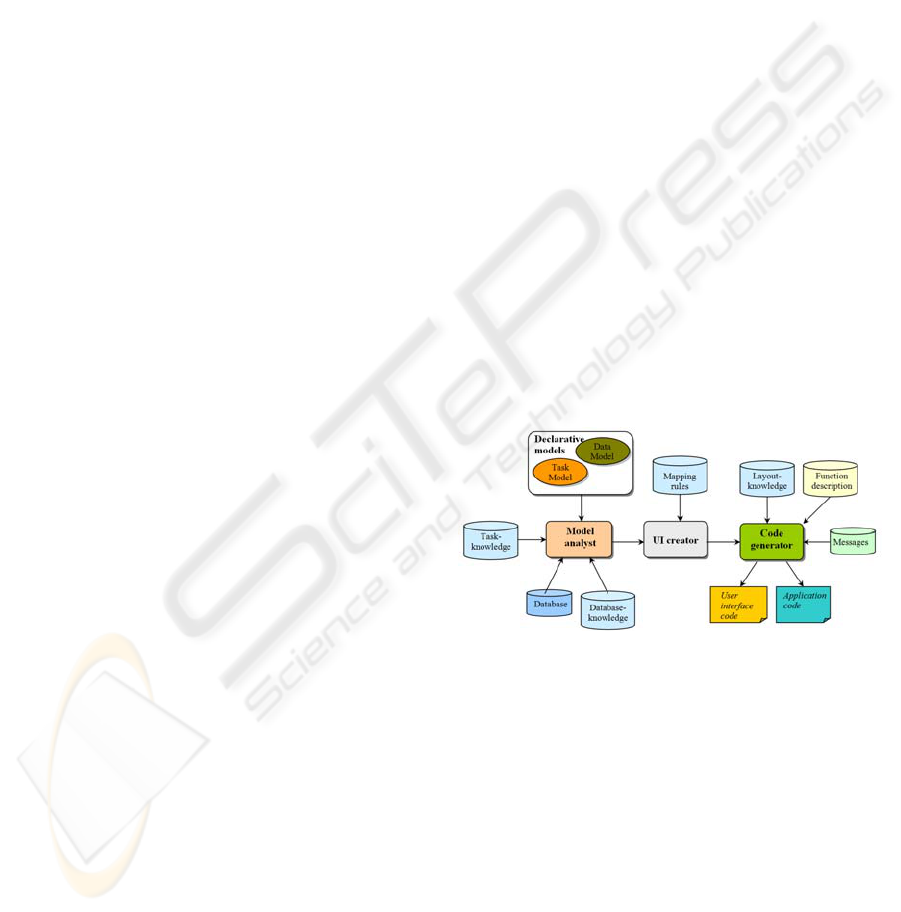
As depicted in Figure 1, in our framework, the
Model analyst uses the task-, data- knowledge bases
and the database to analyze the task and data models
to derive sub-tasks, table objects and column
objects. These sub-tasks have to be related to
column objects manually by the developer. From
these linked objects, the UI creator agent
automatically creates user interface (UI) objects
based on the mapping rules. Once the UI objects
have been created, the code generator agent
generates the code that will implement the UI.
Specifically, our process does not only generate the
user interface code, but also the application code
behind to perform these pre-determined tasks.
In the model analyst process, the sub-tasks are
loaded from the task model which is stored in term
of XML specifications; the data model is loaded
from the database by executing pre-compiled SQL
queries. Executed SQL queries differ if the
databases are multiple since the data model
information is stored specifically in each database.
The sub-tasks having been linked to tables
columns of the data model by the developer, the UI
creator agent creates the Abstract Interaction Objects
(AIOs) based on the column’s attributes and the
relationships between the tables. AIOs are high-level
interactive entities reflecting generic behavioural
properties. Once the AIOs have been created, they
are transformed from AIOs to Concrete Interaction
Objects (CIOs). A CIO is described as a user
interface control unit.
Besides, in order to obtain the desired goal of a
database application task, data queries are also
automatically generated to get or change the
information on the database; these queries are used
by the code generator agent in the application code
generation process.
Once the CIOs have been specified, the code
generator uses the Layout-knowledge base to
generate the user interface code and the Function-
description base to generate the application code
based on these CIOs.
The application code is generated to perform
generic functions of a database application such as
data update, data review, data insertion, …
Figure 1: Main components of our UI and Code
Generation Architecture.
In summary, the components of our UI and Code
Generation Architecture are:
• The Database used to get the information on
and of the data model;
• The Task-knowledge base that describes the
rules of the task model;
• The Mapping rules base that describes the rules
for specifying control types from data types and the
relationships between the tables;
• The Database-knowledge base that describes
generic aspects of the database tasks, the syntax and
the structure of generic tasks and queries;
• The Layout-knowledge base that contains the
ICEIS 2010 - 12th International Conference on Enterprise Information Systems
156
syntactic design guidelines for controls,
windows and other widgets layouts. It also describes
the semantic rules to define the control types;
• The Messages base that contains the generic
messages such as errors, warnings, information to
users messages, …
• The Function description base that describes the
generic functions of a database application.
Our process is divided two main parts. For the
first part, the developer determines the tasks from
which user interfaces can be generated based on the
data model. Specifically these tasks are database
manipulation tasks. The developer then makes the
links between the specified tasks and tables columns
of the data model. The second part analyzes these
objects selected in the first part to specify the AIOs,
CIOs and finally, the user interface code and
application code are automatically generated.
3 UI GENERATOR MODEL
The process proposed in Section 2 is detailed below.
The Model Analyst agent displays the task model
from the XML file (e.g., exported from the CTTE -
ConcurTaskTrees Environment tool (Paternò et al.,
2001) or Teresa (Paternò and Santoro, 2002) and the
data model from the database to the developer. It
determines the tasks from which the UI should be
generated; the application tasks are then linked to
columns in data model by the Developer. Based on
these links, the UI Analyst agent automatically
creates AIOs and that are transformed to CIOs.
Other tasks may be also linked to database functions
(such as insert/delete/update/search/review) by the
Developer; the Method Analyst agent generates the
SQL queries and specifies the methods which are
performed to fulfil the goal of the linked functions.
Finally, the Code Generator agent outputs the user
interface code and application based on the analyzed
results.
The Model Analyzer agent depends on the
Developer agent to analyze and display the task and
data models. The UI Analyst agent also depends on
the Developer agent to make the links between the
application tasks and columns in data model in order
to create the UI objects such as AIOs and CIOs. The
Method Analyst agent depends on the Developer
agent to make the links between the interaction,
abstract tasks and database functions. The Code
Generator agent depends on the UI analyst to create
the UI entities and on the Method analyst to create
the methods. Finally, the Developer agent depends
on Code Generator agent to generate the user
interface code and the application code.
The control flow from the Model Analyst agent
receiving the models to the Code Generator agent
creating the user interface can be supparized as
follows: Once the LoadTaskModel plan reads the
task model from a XML file, it posts a AnalyzeTask
event to the AnalyzeTaskModel plan. The
AnalyzeTaskModel plan detects the AnalyzeTask
event to analyze and decompose the task model in
sub-tasks. In addition, the LoadDataModel plan
received a LoadDataModel event from the
ConnectDatabase plan to load the data model.
Based on the result analyzed above, the
ChooseATask plan selects a task based on which the
user interface will be generated. The
MakeLinkForOperationTask plan makes links
between the operation tasks and the columns in the
data model when it received the LinkOTask event.
The MakeLinkForActionTask plan makes links
between the action tasks and the columns in the data
model when it received the LinkATask event.
Due to the lack of space we will only analyze in
Section 3 the main components (agents and plans) of
the process.
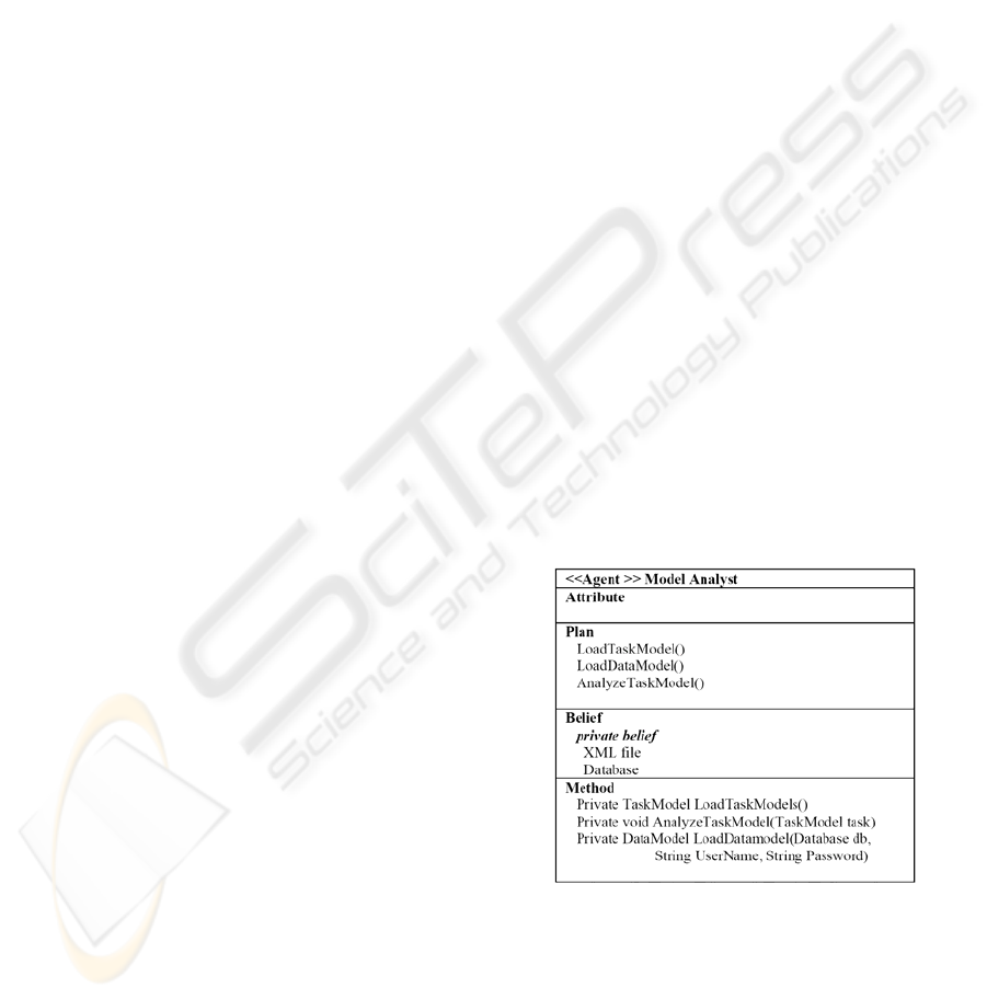
3.1 Main Agents
The Model Analyst agent (Figure 2) uses the
LoadTaskModel plan to load the task model from the
XML file, the LoadDataModel to load the data
model from the database and the AnalyzeTaskModel
to analyze the task model and decompose it in
classified sub-tasks.
Figure 2: Model Analyst Agent Structure.
The Developer agent (Figure 3) uses the
ChooseATaskandClassifyInteractionTasks plan to
choose a database task, which can generate the user
interface based on the data model and to classify the
interaction tasks to operation and action tasks. The
MakeLinkForOperationTask plan is used to make
links between operation tasks and columns in the
USING TASK AND DATA MODELS FOR USER INTERFACE DECLARATIVE GENERATION
157
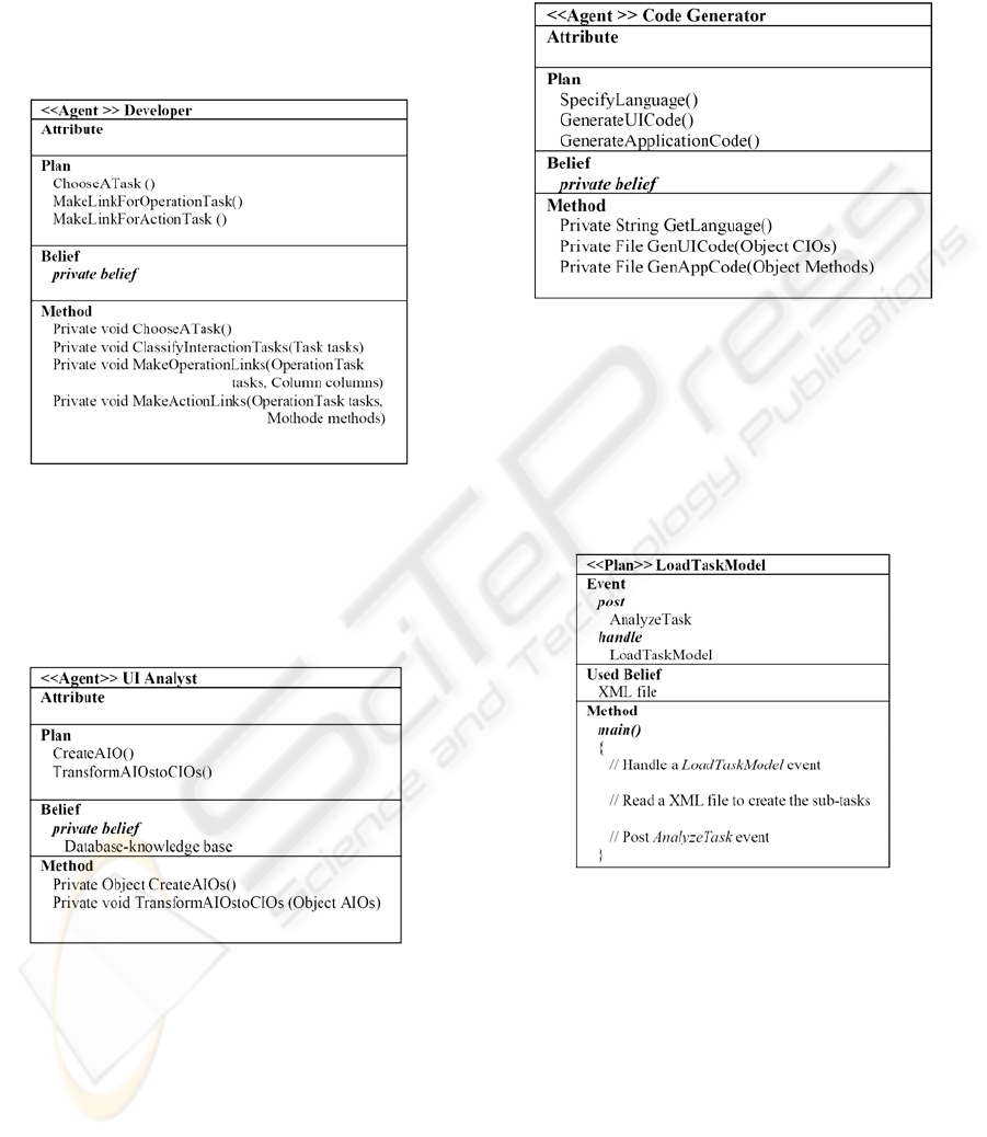
data model. Finally, MakeLinkForActionTask makes
the links between the action tasks and the defined
methods.
The main goal of this agent is to make
associations between existing components in both
models. In our process the components are tasks,
columns and methods defined by the system; the two
models are, of course, task and data models.
Figure 3: Developer Agent Structure.
The UI Analyst agent (Figure 4) uses the
CreateAIO plan to create Abstract Interaction
Objects (AIOs) then these AIOs are transformed to
Concrete Interaction Objects (CIOs) by the
TransformAIOstoCIOs plan.
Figure 4: UI Analyst Agent Structure.
The Code Generator agent (Figure 5) uses the
SpecifyLanguage plan to specify the language used
to perform the user interface determined above, the
GenerateUICode plan to generate the code based on
the determined CIOs and the
GenerateApplicationCode to perform the method
determined in the Method Analyst Agent.
An application program can be divided into two
parts: the user interface and the code behind the
interface that implements the internal logic of the
program and interacts with external entities (e.g.,
database servers). The user interface is determined
by the agents presented above; the Code Generator
agent will generate the code to implement the UI.
Figure 5: Code Generator Agent Structure.
3.2 Main Agent Plans
The LoadTaskModel plan (Figure 6) is used by the
Model Analyst agent to display the task model from
the XML file; this XML file can be built by tools
like CTTE or Teresa. The task’s types are mapped to
action task or operation task.
Figure 6: LoadTaskModel plan structure.
Note that, tasks that are accepted in our process
are modelled up to the atomic level. An atomic task
cannot be decomposed.
An Action task is a task used to describe the
end-user’s command to the system such as close a
dialog, delete a data record, search information,
open a dialog and so on.
An Operation task is a task used to describe the
displaying information to end-user or the receiving
of the information from the end-user.
The LoadDataModel
plan (Figure 7) is used to
load a data model from a database specified by the
developer. Once the LoadDataModel plan receives a
ICEIS 2010 - 12th International Conference on Enterprise Information Systems
158
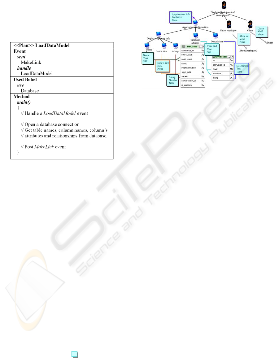
LoadDataModel event, a database connection is
opened based on the type of database (Oracle, SQL
server, MySQL …) and connection parameters. The
Data model is loaded by executing the SQL queries
to get the table names, column names, column’s
attributes, constraints and relationships between
tables. Finally, the LoadDataModel
plan sends the
MakeLink event to the Developer agent.
Figure 7: LoadTaskModel plan structure.
The MakeLinkForOperationTask and
MakeLinkForActionTask
plans are used by the
developer agent to make the links between the
operation tasks and the columns in the data model
and to make the links between the action tasks and
the defined methods.
To make our process more efficient, we define
some generic methods handling performance of a
database task: Display() to display data, New() to
insert data, Delete() to delete data, Update() to
update data, Review() to display data by going next,
previous, last, first, Cancel() to cancel a work, Exit()
to close a dialog or a form.
The CreateAIO plan is used by the UI Analyst
agent to create the AIOs based on the selected
component; specifically, the column’s attributes play
an important role. An AIO is created with an AIO
name, data type and length. For each leaf task in the
tree (Figure 8), an AIO is created. The AIO
attributes are determined based on the column
attributes that this task links to. The attributes of a
column in the data model are data type, length, is-
key, is-null …
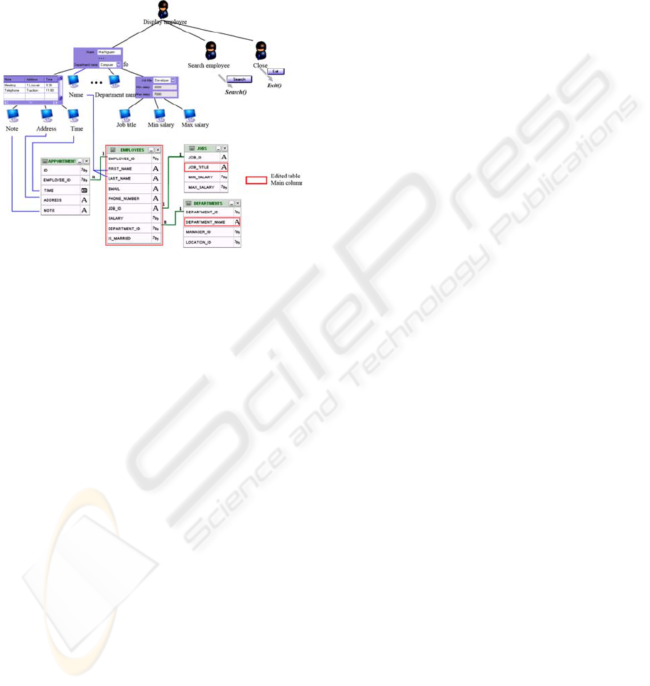
Figure 8 depicts the creating
process of AIOs
based on a task, the components of data model and
the links between them. Each
represents an AIO;
the attributes are represented in order: AIO’s name,
data type and length.
Figure 8: Creating AUIs process.
The TransformAIOstoCIOs plan plays a major
role. It detects the TransformAIOtoCIO event to
transform the AIOs to CIOs. This plan also sends the
GenCode event to the Code Generator agent to
generate the code for performing the user interface
of the task.
AIOs are transformed to CIOs based on the data
type and the relationships between the tables.
Whether the Automatic user interface generation is
successful or not depends on the performance of this
plan. The TransformAIOstoCIOs plan uses all the
existing components of the data model such as
attributes, columns, tables and relationships between
tables. Plans described above use the components of
the data model in the following order: columns,
attributes columns. The tables and their relationships
are also used by the TransformAIOstoCIOs plan.
The Name of a CIO is transformed from the Name of
the corresponding AIO.
Each interface object defined at a higher design
level is assigned to a dialog element (widget) by
examining the facets of the corresponding slot in the
domain model. For example, an AIO of type Text is
assigned to a text field, an AIO of type Boolean is
assigned to a check-box or radio control, and an AIO
of type Date is assigned to a date picker. Besides,
our process also uses the relationships between the
tables in the data model to regroup the CIOs together
if they describe the same object such as employee,
job, department, … objects. For example: the CIOs
Job title, Min Salary, and Max salary belong to the
same CIO group.
The notions of edited table and main column of a
table depicted in Figure 9 are described as:
• An Edited table is a table determined by the
developer. One can add a new data into, get data
from, search data on, … an Edited table if a task is
USING TASK AND DATA MODELS FOR USER INTERFACE DECLARATIVE GENERATION
159
linked to generic methods New(), Delete(),
Search() …
• A Main column of a table which relates to
an Edited table through a 1-1 or n-1 relationship is
a column determined by the developer. A Main
column is used to determine the control type in the
next step.
Figure 9: TransformAIOstoCIOs plan structure.
4 CONCLUSIONS
We have proposed here a framework whose purpose
is to drive the automatic database user interface
design and code behind generation from both the
task model and data model combined together.
Section 2 has presented our automatic UI and
code generation process taken together the task and
data models. Section 3 has explained the roles of the
main agents and plans participating in this process.
This framework has aimed at offering a low cost,
short time-to-implementation and efficient
development environment from the business user
side. Indeed, the objective is not to provide a tool for
professional database management development
staff but to support non-IT end-user with the
generation of database applications they do not need
to program anymore.
REFERENCES
Puerta, A., Eriksson, H., Gennari, J., Musen, M., 1994.
Beyond Data Models for Automated User Interface
Generation. In Proc. of HCI'94: People and
Computers. Glasgow, UK, pp. 353–366.
Da Silva P., Griffiths T., Paton, N., 2000. Generating user
interface code in a model based user interface
development environment. In Proc. of Advanced
Visual Interfaces (AVI'00), New York, pp. 155–160.
Schlungbaum, E, Elwert T., 1996. Automatic user
interface generation from declarative models. In: J.
Vanderdonckt, Ed, Proceedings of Computer Aided
Design of User Interfaces (CADUI'96), pp. 3–18.
Janssen, C., Weisbecker, A., Ziegler, J., 1993. Generating
User Interfaces from Data Models and Dialogue Net
Specifications. In Ashlund S., Mullet K., Henderson
A., Hollnagel E., White T. (eds.): Proc. of
INTERCHI'93. New York, pp. 418-423.
Moroney, L., MacDonald, M., 2006. ASP.NET
Applications in Pro ASP.NET 1.1 in VB .NET From
Professional to Expert, Apress, pp. 183- 230.
Griths, T., Barclay, P., McKirdy, J., Paton, N., Gray, P.,
Kennedy, J., Cooper, R., Goble, C., West, A., Smyth,
M., 1999. Teallach: A Model-Based User Interface
Development Environment for Object Databases. In
Proc. of UIDIS'99, pp. 86-96, Edinburgh, UK.
Eisenstein, J., Puerta, A., 2000. Adaptation in automated
user-interface design, Proceedings of the 5th
international conference on Intelligent user interfaces,
p.74-81, New Orleans, Louisiana.
Olsen, D., Foley, J., Hudson, S., Miller, J., Myers, B.,
1993. Research di-rections for user interface software
tools, Behaviour & Technology, Vol. 12, No. 2, pp.
81-97.
de Baar, D., Foley, J.D., Mullet E., 1992. Coupling
Application Design and User Interface Design, CHI'92
Conference Proc., Monterey, pp. 259-266.
Wooldridge, M., Jennings, N., 1995. “Intelligent agents:
Theory and practice”, The knowledge Engineering
Review, Volume 10, Number 2, pp 115-152.
Paternò, F., Mancini, C., Meniconi, S., 1997.
Concurtasktrees: A diagrammatic notation for
specifying task models. In S. Howard, J. Hammond,
and G. Lindgaard, editors, Human-Computer
Interaction INTERACT, pages 362–369.
Paternò, F., Mori, G., Galiberti, R., 2001. CTTE: an
environment for analysis and development of task
models of cooperative applications. In CHI ’01
Extended Abstracts on Human Factors in Computer
Systems. Seattle, Mar., ACM Press, 21–22.
Paternò, F., Santoro, C., 2002. One Model, Many
Interfaces. Proc. of CADUI'2002, Kluwer. pp.143-
154.
ICEIS 2010 - 12th International Conference on Enterprise Information Systems
160
