A MULTI-VIEW STEREO SYSTEM FOR ARTICULATED
MOTION ANALYSIS
Francesco Setti, Mariolino De Cecco
Department of Structural and Mechanical Engineering, University of Trento, via Mesiano 77, Trento, Italy
Alessio Del Bue
∗
Istituto Italiano di Tecnologia, Via Morego 30, 16163 Genova, Italy
Keywords:
Human motion analysis, Multi-view stereo, 3D reconstruction, Motion segmentation.
Abstract:
In this paper we present a system for the motion segmentation of a human arm and the determination of
its internal joint characteristics (position and degrees of freedom). In particular, we are interested in the
segmentation of a set of 3D points lying over a pair of non-rigid bodies (arm and forearm) connected through
a rotational joint (elbow). The complexity of the problem resides in the non-rigidity of the motion given by
the human articulations and the soft tissues of the body (e.g. skin and muscles). In this work we address the
aspects of 3D reconstruction by multi-stereo vision, frame-by-frame matching of the feature points, motion
segmentation and the joint characteristics determination.
1 INTRODUCTION
The interest on 3D reconstruction and motion anal-
ysis devices is growing due to the wide application
of these systems in different industrial and scientific
fields. The recent advancements in Computer Vi-
sion have impacted highly in the movie and advertise-
ment industries (Boujou, 2009), in the medical analy-
sis area, in video-surveillance applications (Ioannidis
et al., 2007) and in biomechanics studies of the hu-
man body (Corazza et al., 2007; Fayad et al., 2009).
However, the strongest limitation for several systems
is their restriction to deal with rigid bodies only. A
shape which is deforming introduces new challenges,
the object can vary arbitrary and the observed shape
may have different articulations not known a priori.
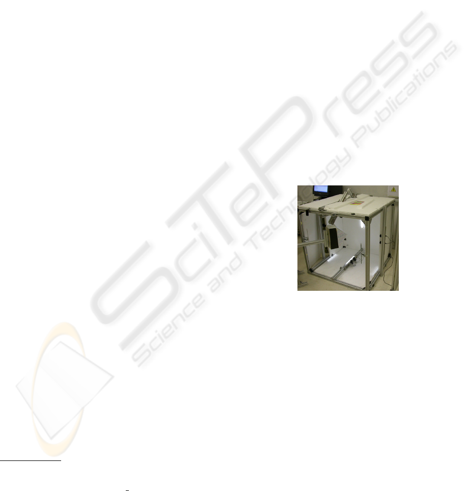
The vision system here developed is tuned to
tackle such problems. It consists of a set of twelve
cameras in a stereo pair setup (see Figure 1) and a spe-
cial pattern with distinctive markers to overlay over
the subject. Our application is driven towards the
analysis of human motion but it is general in his con-
cept and applicable to different shapes. Given the pat-
∗
This work was partially supported by Delta R&S,
Fundac¸
˜
ao para a Ci
ˆ
encia e a Tecnologia (ISR/IST pluri-
annual funding) through the POS Conhecimento Program
(include FEDER funds) and grant MODI-PTDC/EEA-
ACR/72201/2006. A special thanks to Jo
˜
ao Fayad for help-
ful suggestions.
Figure 1: The image acquisition system used in our experi-
ments.
tern and multiple views the proposed vision system is
able to:
• For each frame obtain a 3D reconstruction given
the markers position;
• Match 3D points at each pair of frames given the
repetitive structure of the marker pattern;
• Segment articulated body parts if such motion ex-
ists;
• Compute the joint position of the two bodies.
The final aim of our system is to describe the full ar-
ticulated body in 3D and to infer its motion properties
automatically from a set of images given a known pat-
tern. Our application domain is the analysis of the ma-
nipulation skill of humans where accurate measure-
ments of the articulation are fundamental.
367
Setti F., De Cecco M. and Del Bue A. (2010).
A MULTI-VIEW STEREO SYSTEM FOR ARTICULATED MOTION ANALYSIS.
In Proceedings of the International Conference on Computer Vision Theory and Applications, pages 367-372
DOI: 10.5220/0002847303670372
Copyright
c
SciTePress
(a) left image, frame 1 (b) right image, frame 1
(c) left image, frame 5 (d) right image, frame 5
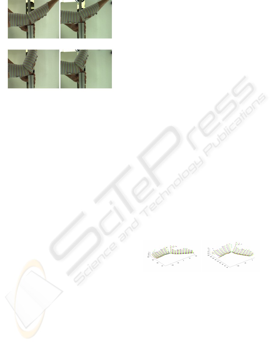
Figure 2: An example of a set of images acquired from the
stereo-pairs.
This paper first describes the image acquisition
system and the 3D reconstruction process in Section
2. The next Section 3 shows how the pairwise 3D
matching is done exploiting the particular structure of
the pattern. Section 4 presents the segmentation algo-
rithm based on the motion of the object shape. Section
5 describes the articulated joint position computation
and finally Section 6 presents some real experimental
results with a bending arm. Section 7 finally proposes
a discussion of the system.
2 IMAGE ACQUISITION AND 3D
RECONSTRUCTION
The image acquisition system is able to reconstruct
the position of a set of points belonging to a generic
surface located in a given working space. The re-
lated software manages 12 cameras, connected in a
configuration of 6 stereo-pairs. The camera model
parameters are estimated through camera calibration
and an accurate description of this stage can be found
in (De Cecco et al., 2009).
Figure 2 shows the 3D reconstruction for the first
and last frame acquired from the system for an eight
frame long sequence. The reconstruction procedure
is based on the acquisition of color markers super-
imposed on the shape by means of a wearable cloth.
Marker matching between cameras is performed us-
ing both epipolar geometry and pattern geometry to
minimize outliers. In particular the pattern is a se-
quence of alternate stripes of color markers of four
different colors (red, green, yellow and blue).
We employ a cloth on which a pattern of mark-
ers is painted. There are other systems that make use
of artificial markers on cloths. (Scholz and Magnor,
2006) use a circular patterns of five different colors
similar to the one used in our setup. (White et al.,
2007) adopt a mesh of triangular geometric shapes
with random colors. One of the main challenges is the
correct matching of each marker. In our case we use a
highly symmetric aligned pattern of circular markers
as shown on the arm in figure 2. Correspondences are
solved by first clustering the lines and than searching
for the best matches between lines. Although more
computation is needed we believe this method is more
robust when dealing with high curvature objects and
when the lighting conditions are not optimal (White
et al., 2007).
Each stereo pair provides the depth evaluation of
each point in the field of view; a compatibility anal-
ysis between points reconstructed from more than
one stereo pair is performed by using Mahalanobis
distance and the fusion of compatible points is per-
formed employing a Bayesian approach (De Cecco
et al., 2009). The output of the 3D reconstruction
stage is a n × 5 matrix M for each frame such that:
M =
x
1
y
1
z
1
col
1
unc
1
.
.
.
.
.
.
.
.
.
.
.
.
.
.
.
x
n
y
n
z
n
col
n
unc
n
where n is the number of reconstructed points. The
first three columns of M are the 3D coordinates x, y
and z of the point. The fourth column is a scalar that
indicate the color of the marker while the last one is
a scalar that gives the uncertainty of the reconstructed
point. Figure 3 shows an example of the 3D recon-
struction for an eight frames image sequence where
the captured non-rigid motion is an arm bending as
presented in Figure 3 using a single stereo pair view.
Figure 3: The left and right image shows the first and last
frame respectively of the eight frame sequence used for the
3D reconstruction of the human arm.
3 TRAJECTORY MATRIX
The previous reconstruction stage provides a set of
unordered 3D coordinates at each image frame. The
next task is to match each 3D point in a given frame
the corresponding 3D point in the following frame.
This is a fundamental step in order to infer the global
properties of the non-rigid image shape (i.e. its mo-
tion). This 3D matching stage aims to form a com-
plete measurement matrix W in which each column
VISAPP 2010 - International Conference on Computer Vision Theory and Applications
368
of the matrix represents the 3D trajectory of a point.
As an example, consider the first two frames of a se-
quence. After 3D reconstruction we have two matri-
ces M
1
and M
2
with n and m points where in gen-
eral n 6= m. The output of the frame-by-frame points
matching algorithm is a vector
P
2
=
P
2
1
.
.
.
P
2
n
with the same number of rows of the matrix M
1
, each
row contains the index of the point in the second
frame matched with the one in the first frame. If a
point of the first frame has no given assignment in the
second frame, the value in P
2
will be NaN.
3.1 Matching using Nearest Neighbor
Our main contribution is to propose a set of matching
algorithms robust to non-rigid deformations using the
properties of the given pattern. One of the simplest
algorithm we can use is a revisited version of the clas-
sical Nearest Neighbor (NN) approach to account for
the different color assigned to each 3D point in both
frames. The algorithm is composed by the steps be-
low:
1. Compute the metric distance matrix between each
pair of points of the same color in the two frames;
the pairs of points of different colors the corre-
spondent value is NaN.
2. Compute the minimum distance for each point of
f rame
1
where NaN values are ignored. We obtain
a n × 2 matrix D
min
where the columns represent
the minimum distance and the index of the nearest
point.
3. If the minimum distance between two points is
lower than a threshold and the association is
unique, the association is considered valid, oth-
erwise it will be deleted.
The threshold is automatically computed from the
mean distance, the mean of the first column of the
matrix D
min
, multiplied by a coefficient. This algo-
rithm gives reasonable results under the hypothesis
that the movement of the feature between two suc-
cessive frames is small with respect to the distance
between the features in a single frame. This means
that the motion of the bodies is tiny with respect to
the frame rate and the features spatial density.
3.2 Matching using NN and Procrustes
Analysis
We also propose to combine NN and Procrustes Anal-
ysis (PA) theory. The algorithm is composed by the
three distinctive stages.
1. Stripe Sorting. Given the pattern repetitive struc-
ture, it is possible to associate points with the same
color to a set of stripes. Each stripe is sorted along
the principal directions of the 3D shape at the given
frame.
2. Stripe Matching. In this stage we match each
stripe in the first frame to a stripe in the second frame.
This association is made using a NN approach on the
centroid of each stripe using again the color as a dis-
criminative feature.
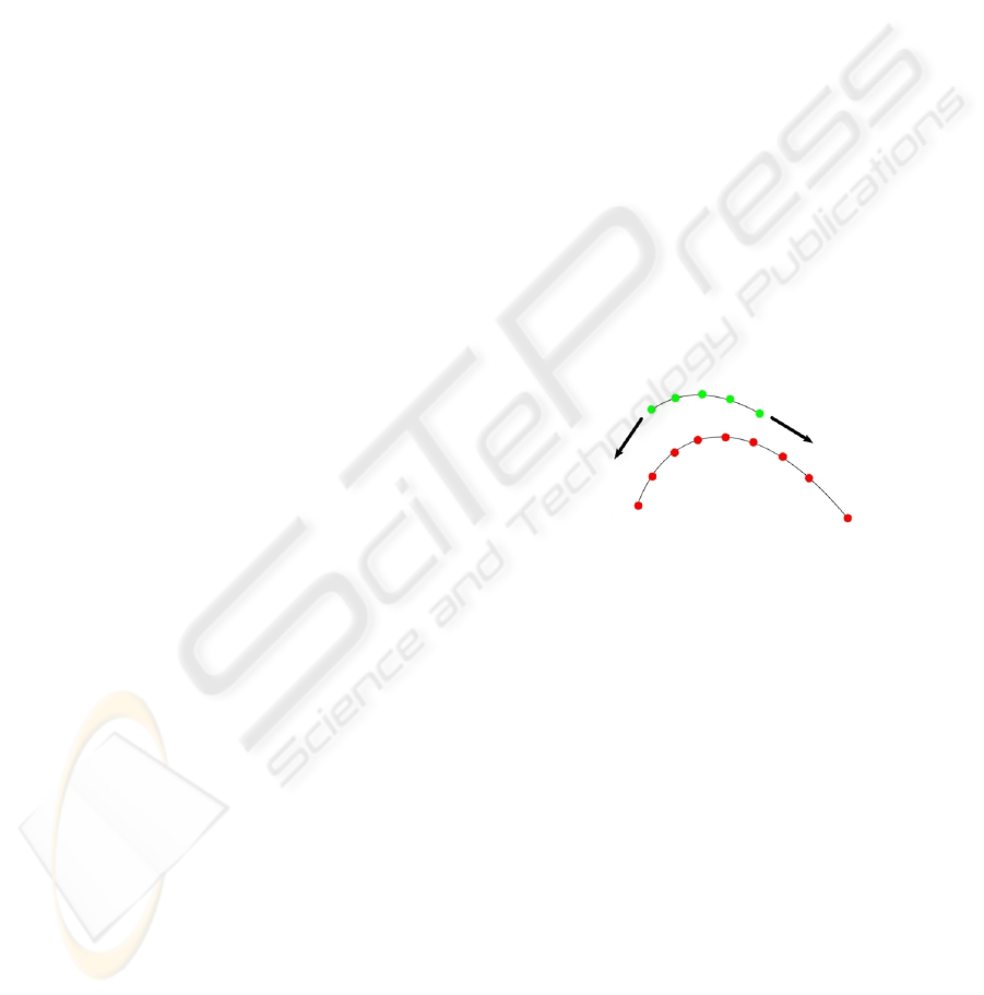
3. Match 3D Points in Each Stripe. For two
matched stripes, we select first the stripe containing
less 3D points. Then we sequentially assign these
points to the 3D points of the other stripe and we reg-
ister the two sets using PA (Kanatani, 1996) (Figure
4 shows a graphical explanation). We selected the as-
signment which results in the minimum 3D error after
registration.
Figure 4: The points on the top line slide over the point of
the bottom line. At each slide, registration with PA is made
with the corresponding points. The 3D residual between
the registered set of points is then used as the criteria for the
best match.
Stage 1 and 2 are based on the observation that a
NN over the centroid of the stripes is more robust to
deformation and more computationally efficient than
performing a NN on each 3D point. Especially for the
second step, if the deforming body can be considered
locally rigid on the stripe, the rigid registration by PA
give low 3D residual if the matching is correct.
The proposed algorithm is very robust for short
movements with respect to the stripe-by-stripe dis-
tance. If the displacement between the centroids of
the same stripe in two following frames is compara-
ble to the stripe-by-stripe distance, this method is no
longer robust. In this case we can use a similar algo-
rithm, Local Procrustes Analysis (LPA), in which we
consider not only the associated stripe for the PA, but
also the n-nearest. This method is more robust than
the previous one in the case of large displacements.
Unfortunately this modification introduces more sen-
A MULTI-VIEW STEREO SYSTEM FOR ARTICULATED MOTION ANALYSIS
369
sibility to deformations.
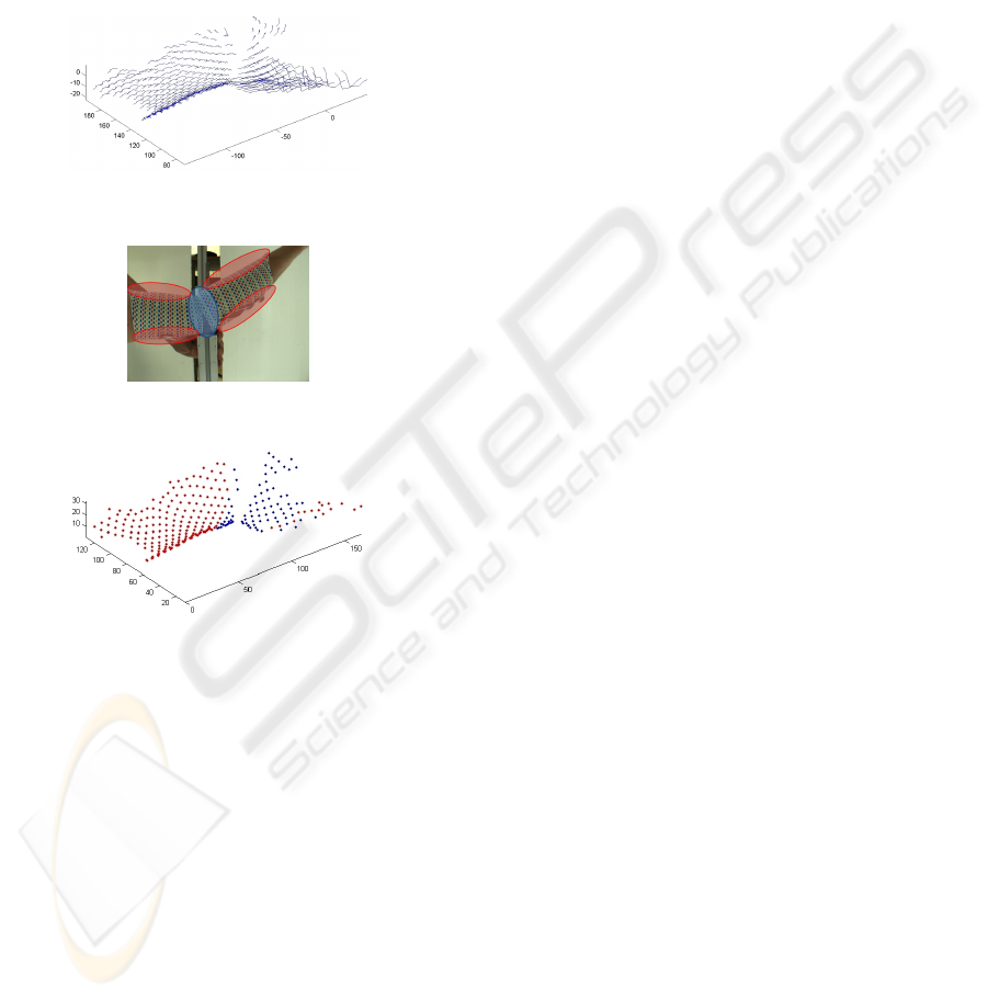
Once we have a frame-by-frame matching array
for each pair of successive frames, we can build a tra-
jectory matrix W taking into account only the features
tracked in all the frames. The trajectories of the full
tracked points in the example case are shown in Fig-
ure 5. In this algorithm we consider only the points
tracked in all the frames, the markers tracked only in
a few frames could be considered with a dedicated
missing data algorithm.
Figure 5: The 3D point matching between five successive
frames.
Figure 6: The expected critical zone in the segmentation
stage: the border zone (blue) and the joint zone (red).
Figure 7: Human arm segmentation using the Generalized
Principal Component Analysis (GPCA).
4 MOTION SEGMENTATION
Once the matching problem is solved, the matrix W
stores the correct temporal information of the 3D tra-
jectories of the non-rigid body. In order to compute
the location of a joint, we need now to segment the
full non-rigid 3D motion into a subset of relevant rigid
motions. In the experimental case here presented this
means to assign each 3D trajectory in W to two clus-
ters of points lying on the forearm and on the arm.
In the following section we evaluated the results ob-
tained by a subset of these methods applied and mod-
ified for the 3D segmentation problem. In particular,
we assess the performances of three algorithms: Gen-
eralized Principal Component Analysis (GPCA) (Vi-
dal et al., 2005), Subspace RANSAC (Fischler and
Bolles, 1987; Tron and Vidal, 2007) and Local Sub-
space Affinity (LSA) (Yan and Pollefeys, 2008).
These algorithms obtains reasonable results for
2D motion segmentation tasks with the LSA approach
obtaining the best results (Tron and Vidal, 2007). In
the following, we evaluate their quality with bodies
that show a certain degree of non-rigidity and soft tis-
sue artifacts. In general, we expect decreasing perfor-
mance in two different regions:
border zone where the marker’s movement could
be affected by the muscle tension. Regions are
marked with blue in Figure 6.
joint zone where the two bodies are not well sepa-
rated because of the geometrical conformation of
the natural joint (elbow). The region is marked
with red in Figure 6.
4.1 GPCA Algorithm
The GPCA (Vidal et al., 2005) method was intro-
duced with the purpose of segmenting data lying on
multiple subspaces. This is also the case for 3D
shapes moving and articulating since their trajectories
lie on different subspaces. The method is algebraic
and it first fits the union of the subspaces to a set of
polynomials with a certain degree. Then subspaces
are clustered using the derivative at a point which
gives the normal to the subspace containing the point.
Figure 7 shows the segmentation results using GPCA
over the arm movement 3D data. The segmentation
error is about 25% in this test showing several outliers
far from the joint and thus from the expected regions.
This unexpected result may be a consequence of the
non-rigid motion of the body parts.
4.2 RANSAC Algorithm
The method is based on the selection of the best
model which fit the inlier data. In order to estimate the
putative models, candidates set of points are chosen
randomly and then the residual given the fitted model
is stored. After several random sampling, the model
which fits best the inliers is chosen. For our case, this
algorithm is the worst performing of the three obtain-
ing a segmentation error of approximately 50% of the
given points for this dataset. Figure 8 shows that most
of the errors are located at the border zone, where we
expect errors because the movement of the markers
could be affected by the muscle tension. This method
gives errors in both the expected regions, joint and
border, but in general we have several errors also in
similar critical region as for the GPCA algorithm.
VISAPP 2010 - International Conference on Computer Vision Theory and Applications
370
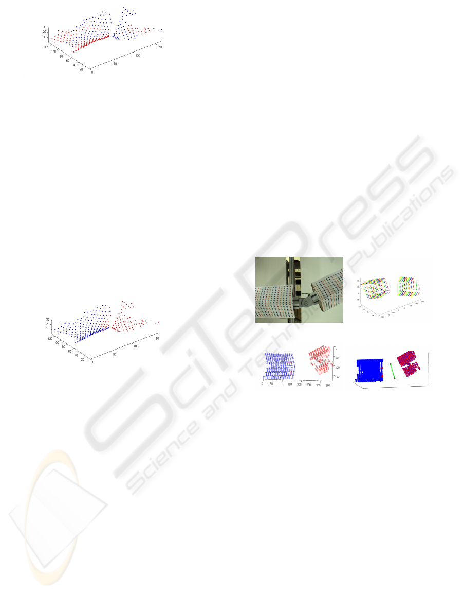
Figure 8: Human arm segmentation using the RANSAC.
4.3 LSA Algorithm
The LSA approach (Yan and Pollefeys, 2008) uses
spectral analysis in order to define the data clusters
which refer to different motion subspaces. It is based
on local subspace fitting in the surrounding of each
trajectory followed by spectral clustering. Figure 9
shows that the LSA algorithm is the best performing
between the tested three with a total segmentation er-
ror of about 8%. The algorithm correctly estimate the
points in the border zone, but we have few errors in
the joint zone. Interestingly, the mistakes out of the
critical expected regions are rather few. This is prob-
ably related to the fact that the LSA algorithm is more
robust to the noise possibly introduced by soft-tissue
artifacts than the other two considered approaches.
Figure 9: Human arm segmentation using the Local Sub-
space Affinity (LSA).
5 JOINT RECONSTRUCTION
The theoretical property used to perform the compu-
tation of the joint is that the subspaces computed from
the trajectories of two body parts intersects. Such
common intersection can be used to identify the joint
position and properties as noticed by (Yan and Polle-
feys, 2008; Tresadern and Reid, 2005) for image data
and used by (Fayad and P. M. Q. Aguiar, 2009) for
3D data. We use the computational tool developed in
the latter work to perform the estimation of the joint
position.
In this stage we have two critical aspects. First,
outliers after the segmentation stage may cause insta-
bility in the estimation of the joint. The second prob-
lem is the planarity of the reconstructed points; in this
case the configuration would be degenerate thus intro-
ducing some instability in the computation of the joint
position and sensibility to noise, and so the computa-
tion of some internal steps of the algorithm can be
affected from matrix rank deficiency. One more crit-
ical point in this case is the co-planarity of the points
and the motion.
6 EXPERIMENTAL RESULTS
For the evaluation of this framework we developed
two experiments. In the first, we used two exactly
rigid bodies (two boxes) linked by a mechanical joint.
This setup has the aim to test the system performance
when there are no soft tissue artifacts. In the second
we tested our system using a real human arm.
Figure 10 resumes the results for the first test. The
sequence is composed from 15 frames acquired from
2 stereo pairs; matching is performed by using the
novel algorithm that combine NN and PA. The seg-
mentation using LSA algorithm gives a segmentation
error of only 1% given the ground truth showing the
good performance of this method with rigid bodies.
(a) Original image. (b) Sample frame.
(c) LSA segmentation. (d) Estimated Joint.
Figure 10: The first experiment setup. The images show: a)
a sample frame, b) a reconstructed frames, c) the segmenta-
tion result using LSA and d) the estimated axial joint (red).
In the second experiment we have acquired a se-
quence of a human arm performing a bending move-
ment and Figure 11 resumes the results. In this case
we used a sequence of 8 frames acquired from a sin-
gle stereo pair. The matching is performed again with
the combined NN and PA. The total segmentation er-
ror using LSA algorithm is about 8%. Figure 11(d)
shows the estimated rotational joint, the 3D position
of the elbow. The first approximation of the human
elbow is an axial joint, this is a good model when we
consider a low number of feature points; in this case
we have over 300 feature points near the elbow, and
so the deformation of the skin surface introduce sec-
ondary motions. For this reason we model the elbow
joint as a generic rotational joint.
A MULTI-VIEW STEREO SYSTEM FOR ARTICULATED MOTION ANALYSIS
371

(a) Original image. (b) Sample frame.
(c) LSA segmentation. (d) Estimated Joint.
Figure 11: The second experiment setup. The images show:
a) a sample frame, b) a reconstructed frames, c) the segmen-
tation result and d) the estimated rotational joint (red).
7 CONCLUSIONS
In this work we address the problem of the 3D mo-
tion segmentation of a non-rigid pair of bodies (a hu-
man arm and forearm) connected by a rotational joint.
In such regard we develop all the stages of the mo-
tion segmentation procedure from the acquisition to
the joint parameters estimation. The main novelty of
the presented approach resides in the 3D point match-
ing stage which has to cope with soft tissue artifacts
in the data. The multi camera facility is able to esti-
mate the position in 3D space of each marker with an
accuracy of about 0.5mm and a maximum resolution
of 5 markers per square centimeter. The 95% ellipse
of uncertainty associated with each marker location
is estimated taking into account both the setup intrin-
sic/extrinsic parameters and the accuracy of the mark-
ers acquired images. We also carried out an evalua-
tion of standard motion segmentation algorithm in the
case of articulated bodies which present soft-tissue
artifacts. The LSA approach is the best performing
method for the test case showed in this work but more
experimental evidence is required to asses the algo-
rithms with different body parts.
To evaluate the localization of the joint we used
both the human arm sequence and the sequence of
two bodies constrained by a rotational joint. In the
latter case the outcome was an accurate estimation of
the joint location. In the first case we performed two
relative motions between arm and forearm. When the
wrist rotates together with the elbow the joint estima-
tion as a single degree of freedom constraint failed to
estimate the correct location of the elbow. This can
be easily explained due to the complex relative mo-
tion involving at least two degrees of freedom. When
the wrist is held at a constant attitude with respect to
the elbow the joint was correctly estimated.
REFERENCES
Boujou (2009). Boujou. http://www.vicon.com/boujou/.
Corazza, S., M
¨
undermann, L., and Andriacchi, T. (2007).
A framework for the functional identification of
joint centers using markerless motion capture, vali-
dation for the hip joint. Journal of Biomechanics,
40(15):3510–3515.
De Cecco, M., Pertile, M., Baglivo, L., Lunardelli, M.,
Setti, F., and Tavernini, M. (2009). A unified frame-
work for uncertainty, compatibility analysis and data
fusion for multi-stereo 3d shape estimation. IEEE
Transactions on Instrumentation Measurements. Ac-
cepted for publication.
Fayad, J., Del Bue, A., Agapito, L., and Aguiar, P. (2009).
Human body modelling using quadratic deformations.
In 7th EUROMECH Solid Mechanics Conference, Lis-
bon, Portugal.
Fayad, J. K. and P. M. Q. Aguiar, A. D. B. (2009). A
weighted factorization approach for articulated mo-
tion modelling. In Multibody Dynamics 2009, War-
saw, Poland, volume 2, pages 1110–1115.
Fischler, M. A. and Bolles, R. C. (1987). Random sample
consensus: A paradigm for model fitting with applica-
tions to image analysis and automated cartography. In
Fischler, M. A. and Firschein, O., editors, Readings in
Computer Vision: Issues, Problems, Principles, and
Paradigms, pages 726–740. Los Altos, CA.
Ioannidis, D., Tzovaras, D., Damousis, I. G., Argyropoulos,
S., and Moustakas, K. (2007). Gait recognition using
compact feature extraction transforms and depth infor-
mation. IEEE Transactions on Information Forensics
and Security, 2:623–630.
Kanatani, K. (1996). Statistical optimization for geometric
computation: theory and practice. Elsevier Science
Inc. New York, NY, USA.
Scholz, V. and Magnor, M. (2006). Multi-view video
capture of garment motion. Proceedings of IEEE
Workshop on Content Generation and Coding for 3D-
Television, pages 1–4.
Tresadern, P. and Reid, I. (2005). Articulated structure from
motion by factorization. In Proc. IEEE Conference on
Computer Vision and Pattern Recognition, San Diego,
California, volume 2, pages 1110–1115.
Tron, R. and Vidal, R. (2007). A benchmark for the compar-
ison of 3-d motion segmentation algorithms. In IEEE
conference on computer vision and pattern recogni-
tion, volume 4.
Vidal, R., Ma, Y., and Sastry, S. (2005). Generalized
principal component analysis (gpca). IEEE Transac-
tions on Pattern Analysis and Machine Intelligence,
27(12):1945–1959.
White, R., Crane, K., and Forsyth, D. (2007). Capturing
and animating occluded cloth. ACM Transaction on
Graphics.
Yan, J. and Pollefeys, M. (2008). A factorization-based
approach for articulated non-rigid shape, motion and
kinematic chain recovery from video. IEEE Transac-
tions on Pattern Analysis and Machine Intelligence,
30(5).
VISAPP 2010 - International Conference on Computer Vision Theory and Applications
372
