
TIME-OF-FLIGHT BASED SCENE RECONSTRUCTION
WITH A MESH PROCESSING TOOL FOR MODEL
BASED CAMERA TRACKING
Svenja Kahn, Harald Wuest
Fraunhofer Institute for Computer Graphics Research, Fraunhoferstr. 5, 64283 Darmstadt, Germany
Dieter W. Fellner
Interactive Graphics Systems Group, Technische Universit¨at Darmstadt, Fraunhoferstr. 5, 64283 Darmstadt, Germany
Keywords:
Markerless camera tracking, Model-based tracking, 3d reconstruction, Time-of-flight, Sensor fusion, Aug-
mented reality.
Abstract:
The most challenging algorithmical task for markerless Augmented Reality applications is the robust estima-
tion of the camera pose. With a given 3D model of a scene the camera pose can be estimated via model-based
camera tracking without the need to manipulate the scene with fiducial markers. Up to now, the bottleneck
of model-based camera tracking is the availability of such a 3D model. Recently time-of-flight cameras were
developed which acquire depth images in real time. With a sensor fusion approach combining the color data
of a 2D color camera and the 3D measurements of a time-of-flight camera we acquire a textured 3D model of
a scene. We propose a semi-manual reconstruction step in which the alignment of several submeshes with a
mesh processing tool is supervised by the user to ensure a correct alignment. The evaluation of our approach
shows its applicability for reconstructing a 3D model which is suitable for model-based camera tracking even
for objects which are difficult to measure reliably with a time-of-flight camera due to their demanding surface
characteristics.
1 MOTIVATION
Markerless camera pose estimation is one of the most
callenging aspects of Augmented Reality applica-
tions. Reliable and often used methods to estimate
the camera pose without using markers are model-
based tracking approaches (Lepetit and Fua, 2005).
Up to now, the availability of a 3D model of a scene is
the bottleneck of model-based approaches. For many
scenes a 3D model is either not available or outdated,
so a 3D model of the scene has to be reconstructed.
The manual creation of a 3D model is very time-
consuming. This is why there is a strong need for au-
tomatic or semi-automatic acquisition of a 3D model.
We present a semi-automatic approach to recon-
struct a scene model for model-based camera track-
ing which is based on a sensor fusion approach of a
time-of-flight camera (which captures depth images
in real time) and a color camera as well as the use
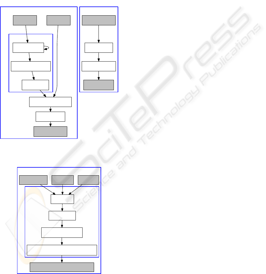
of a mesh processing tool. Our approach comprises
three main tasks which are depicted in figure 1 and
figure 2: First a colored 3D mesh is created from the
data of both sensors (see section 3). Then a 3D model
of the scene is constructed from one or several such
3D meshes (section 4). We propose to use a mesh
processing tool for this task because the 3D measure-
ments of a time-of-flight camera suffer from strong
noise and non-systematic errors. Thus a fully auto-
matic mesh alignment often converges to an incorrect
local minimum which does not correspond to the cor-
rect alignment of the submeshes. After reconstruct-
ing a 3D model of the scene we use the 3D model
for model-based markerless camera tracking (section
5). The evaluation of our approach (section 6) shows
its applicability for reconstructing a 3D model which
is suitable for model-based camera tracking even for
objects which are difficult to measure reliably with a
time-of-flight camera due to their demanding surface
characteristics. In the proposed approach the scene
is reconstructed in an offline preparation step and is
then used for model-based camera tracking with a 2D
camera. In contrast to approaches which simultane-
302
Kahn S., Wuest H. and Fellner D. (2010).
TIME-OF-FLIGHT BASED SCENE RECONSTRUCTION WITH A MESH PROCESSING TOOL FOR MODEL BASED CAMERA TRACKING.
In Proceedings of the International Conference on Computer Vision Theory and Applications, pages 302-309
DOI: 10.5220/0002820903020309
Copyright
c
SciTePress
ously estimate the camera pose and the reconstruction
this approach has the advantage that it is not prone
to drift in the camera pose estimation. Thus a more
stable 3D reconstruction can be achieved than with
online reconstruction. The user input required in the
reconstruction step ensures the correctness of the re-
constructed 3D model. Another advantage is that the
tracking can be donewith any 2D camera and no time-
of-flight camera and no sensor fusion is needed for the
tracking phase.
Acquision of enhanced and colored 3D meshes
Data enhancement
Scene reconstruction
Depth Image Color Image
Temporal filtering
3D data and color fusion
Removing flying pixels
Spatial filtering
Surface creation
3D Mesh (colored)
Several 3D Meshes
Mesh alignment
Mesh simplification
3D Scene Model
Figure 1: 3D mesh creation and scene Reconstruction. The
reconstruction step is accomplished with a mesh processing
tool and can thus be supervised by the user.
Camera Tracking
Color Image KLT Model
KLT tracking
3D Scene Model
Pose calculation
Estimation of 2D position
of lost correspondences
Extraction and backprojection of new features
if not enough valid correspondences
AR Drawer: Color Image & Augmentation
Figure 2: Camera Tracking.
Time-of-flight cameras emit near-infrared modu-
lated light which gets reflected by the scene. The im-
age sensor of the camera then captures the reflected
light. For every pixel the distance to the scene is
calculated by the phase shift of the reflected light.
The distances can be transformed to cartesian coordi-
nates, yielding a 3D measurement per pixel. We use
the time-of-flight camera presented in (Oggier et al.,
2006) which has a resolution of 176 ∗ 144 pixels. In
addition to the 3D measurements the time-of-flight
camera outputs an intensity image which depicts the
amount of light measured by each pixel. The 3D mea-
surements acquired by time-of-flight cameras suffer
from noise and systematic errors. It is thus very im-
portant to filter and enhance the 3D measurements as
described in section 3.1. With a data enhancement
step based on spatial and temporal filtering we can
significantly improve the quality of the 3D measure-
ments which is important for the subsequent camera
tracking step because for that purpose an as accurate
as possible 3D model of the scene is needed.
2 RELATED WORK
Time-of-flight cameras are used for a wide range of
tasks such as Augmented Reality occlusion calcu-
lation or user interaction. A detailed overview of
the current state-of-the-art is given by (Kolb et al.,
2009). In robotics time-of-flight cameras have al-
ready proven to be very useful for 3D scene recon-
struction and robot pose estimation. (Prusak et al.,
2008) use a time-of-flight camera for map building
and pose estimation for robot navigation. They com-
bine a time-of-flight camera with a spherical camera
to create a 3D depth panorama and to estimate the
position of the robot. The 3D depth panorama is cre-
ated by rotating the robot. Then an occupation map
is filled from which a 3D triangle mesh is finally cre-
ated. (May et al., 2008) use a time-of-flight camera
for simultaneous localization and mapping. In their
work a merged point cloud is accumulated based on
the estimated camera poses. In contrast to their ap-
proach we create the 3D mesh in an offline step and
not simultaneously to the estimation of the camera
pose. The reason for this is that in simultaneous lo-
calization and mapping approaches errors in the es-
timation of the camera pose result in errors in the
3D model reconstruction. Thus these approaches are
more prone to drift than approaches in which the re-
construction phase is completed before the camera
tracking is started. (Huhle et al., 2008) combine depth
and color data with measurements of an inertial sen-
sor. They describe how several colored depth images
can automatically be aligned by a combined color-
based and geometric registration. Most similar to our
TIME-OF-FLIGHT BASED SCENE RECONSTRUCTION WITH A MESH PROCESSING TOOL FOR MODEL BASED
CAMERA TRACKING
303
approach is the approach presented by (Schiller et al.,
2008a) who also reconstruct a 3D model for Aug-
mented Reality camera tracking. In their work a col-
ored depth panorama is created by mounting a time-
of-flight camera and a color camera on a controllable
pan-tilt unit. This is a very advantageous approach
because with a controllable pan-tilt unit the camera
pose of every acquired depth image is exactly known.
Thus the reconstruction is very precise and no manual
user interaction is needed at all. Compared to their
approach our approach has the advantage that no con-
trollable pan-tilt unit is needed and that it is not re-
stricted to the reconstruction of 3D panoramas. By
taking depth and color images from several positions
we can reconstruct a full 3D model. In contrast to a
3D panorama, the camera tracking is not restricted to
parts of a scene visible from a single fixed viewpoint.
3 CREATION OF AN ENHANCED
AND COLORED 3D MESH
For the creation of a 3D mesh the quality of the 3D
measurements needs to be enhanced. Then the en-
hanced 3D points get fused with the colors from the
color camera. Finally a triangle mesh surface is cre-
ated based on a distance criterion which is needed to
prevent a surface creation over empty parts of a scene.
3.1 Preprocessing and Filtering
Due to noise and systematic errors in the depth images
the depth data needs to be preprocessed before it can
be used for geometric reconstruction. Depending on
the surface properties, the reflectivity and the distance
of the scene the measured distances can differ from
the real distances by several millimeters or centime-
ters. The measurement accuracy depends strongly on
the material of the objects in the scene. Measurements
are more accurate for objects with materials that re-
flect light in a diffuse manner than for objects with
specular surface properties. Measurements of mate-
rials that reflect only few of the light emitted by the
time-of-flight camera are less accurate than 3D mea-
surements of materials with a high reflectivity.
Temporal Filtering. We use a camera tripod to take
several images of a scene from the same viewpoint
and merge several measurements to get more reliable
measurements. In our setup ten depth images are ac-
quired from each viewpoint. The mean of these mea-
surements is calculated for every pixel. This average
value per pixel reduces the noise which is inherent in
the measurements of single depth images.
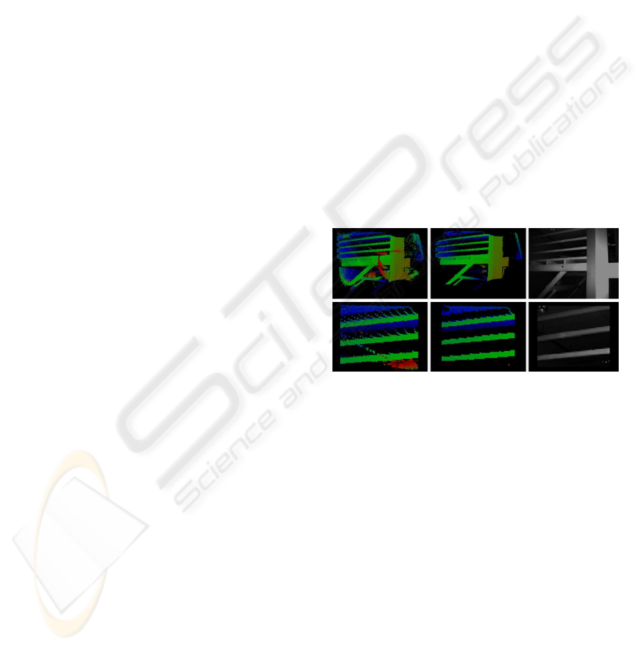
Removing Flying Pixels. Flying pixels occur at
depth discontinuities, where the near-infrared light
emitted by the time-of-flight camera gets reflected in
part by an object in the foreground and in part by an
object in the background. This effect can be seen in
the left column of figure 3. In this figure the 3D mea-
surements of a time-of-flight camera are colored ac-
cording to their distance to the camera. Red 3D points
are close to the camera whereas green 3D points have
a medium distance and blue points are far away. The
right column is the intensity image of the time-of-
flight camera. The second row shows a picture de-
tail. The flying pixels in the left column are erroneous
measurements (there is no object at the position of
these measurements) and must be removed. To re-
move flying pixels and isolated 3D measurements we
apply a filter which examines the eight 3D points cor-
responding to the neighbours of a pixel in the 2D im-
age and rejects pixels if less than n of their neighbours
have a distance below a fixed threshold. In our setup
we chose n=4 and a maximal euclidean distance of
8cm. The result of applying this filter can be seen in
the second column of figure 3.
Figure 3: Removing flying pixels.
Spatial Filtering. To remove random measurement
noise in the images while preserving sharp edges we
apply a bilateral gaussian filter on the depth values.
(Durand and Dorsey, 2002) describe a bilateral fil-
ter for image intensities. We adapted this filter for
depth images. In contrast to a non-bilateral gaussian
filter (which smoothes surfaces but does not preserve
sharp edges and corners) the bilateral filter uses an
additional weighting factor g for each value in the fil-
ter mask. Elements with a similar function value (in
this case 3D points with a similar depth value) get
a higher weighting factor g than 3D measurements
whose depth values differ much. This prevents the
smoothing of edges and corners. Equation 1 repre-
sents a bilateral gaussian filter for a pixel s where k(s)
is a normalization term, G(p) is the gaussian kernel
and g(d,n) is the additional weighting factor which
depends on the distance d between the z values of the
3D points at the pixels s and p. The 3D points (x,y,z)
are in the camera coordinate system and the camera
VISAPP 2010 - International Conference on Computer Vision Theory and Applications
304
points along the z-axis.
z
∗
s
=
1
k(s)
∑
p∈Ω
G(p)g(d,n)z
p
(1)
k(s) =
∑
p∈Ω
G(p)g(d,n) (2)
We chose the function represented by equation 3 as
the weighting factor g. The factor n (n ≥ 1, in our
setup n=10) sets how fast g declines if the z-values
are dissimilar. If n=1 the bilateral filter corresponds
to a standard, non-bilateral gaussian filter.
g(d,n) =
1
n
(1+d)
n
, d = |z
p
− z
s
| (3)
d = |z
p
− z
s
| (4)
The gaussian kernel G is the standard kernel of a
non-bilateral two-dimensional gaussian filter. We use
a 7x7 kernel with σ = 2.0.
G(i, j) =
1
2πσ
2
e
−
i
2
+ j
2
2σ
2
(5)
3.2 Sensor Fusion
To fuse the depth data with color information we
use a camera rig which rigidly couples the time-of-
flight camera and the color camera. For the data fu-
sion the intrinsic camera calibration matrix K of the
color camera and the relative transformation (∆R,∆t)
between the cameras needs to be known. We use
the analysis-by-synthesis approach of (Schiller et al.,
2008b) to calculate the intrinsics as well as the rela-
tive transformation between the cameras.
The time-of-flight camera measures a 3D point p
t
per pixel in its camera coordinate system. To combine
the 3D data with the data from the color camera we
need to find the corresponding color pixel p
c
for every
3D measurement by the following transformations:
p
c
= K(∆Rp
t
+ ∆t) (6)
The 3D point is transformed from the time-of-flight
camera coordinate system to the color camera coor-
dinate system and is then projected to the image co-
ordinate system of the color camera with the given
camera calibration matrix K. To compute the cor-
rect pixel coordinates, the homogeneous image coor-
dinates are distorted with the radial distortion param-
eters of the color camera. The field of view of both
cameras overlaps only partially so for some 3D mea-
surements at the margins there is no color information
available. We keep uncolored parts because they are
useful for the alignment step of the 3D reconstruction:
Two meshes can only be aligned if they have overlap-
ping parts. After the alignment uncolored parts can
be removed where color information is available from
other overlapping meshes.
3.3 Surface Generation from the Point
Set
To create a surface from the measured 3D points we
construct a triangle mesh whose triangles connect
neighbouring points whose depth values are similar.
We do not create a surface of points whose depth val-
ues differ by more than a threshold (in our setup 8cm).
If there is an object in the foreground and another ob-
ject in the background no triangles should be created
in the space between these objects. With the thresh-
old we also prevent a surface generation connecting
measured 3D points with outliers. In the unenhanced
mesh in figure 5 many holes are visible due to 3D
measurements whose depth values differ too much.
This is significantly improved in the enhanced mesh.
4 SCENE RECONSTRUCTION
For some tracking scenarios a single enhanced and
colored 3D mesh created as described in the previ-
ous section can already suffice. If there is a need to
track a larger environment several 3D meshes need to
be combined to a larger 3D model of the scene. We
propose to use a mesh processing tool for this task so
that the user can supervise a correct alignment of the
submeshes.
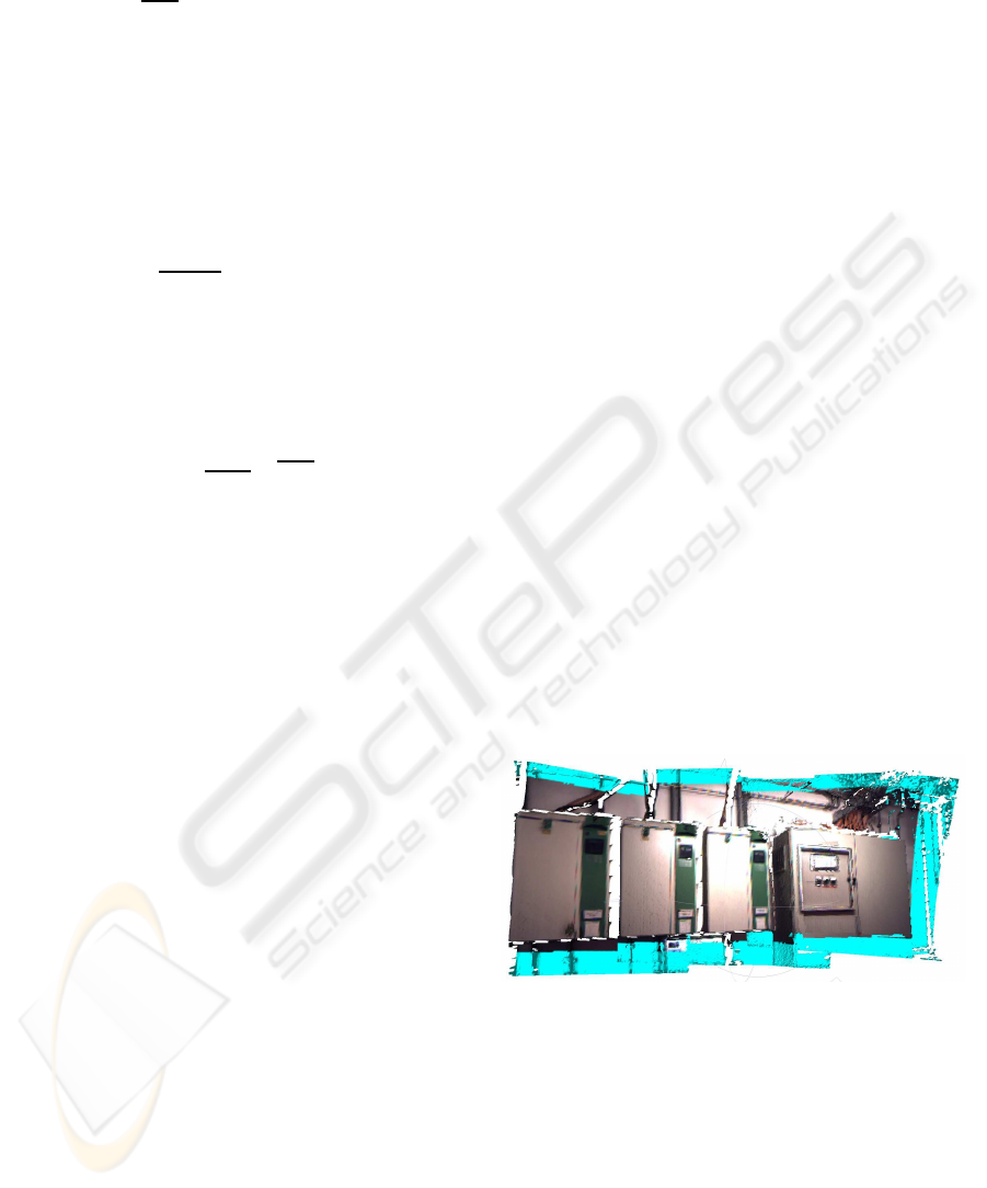
Figure 4: 3D model of a room reconstructed from several
colored time-of-flight images. The surface of 3D measure-
ments for which no color is available is colored in blue.
4.1 Alignment of Depth Images
For the alignment of several colored 3D meshes we
use MeshLab (Cignoni et al., 2008), a powerful mesh
processing tool. Two point sets can initially be
aligned manually by choosing corresponding points
in the two point sets. Then the Iterative Closest Point
(ICP) (Besl and McKay, 1992) algorithm is used to it-
eratively improve the alignment of the two meshes. A
TIME-OF-FLIGHT BASED SCENE RECONSTRUCTION WITH A MESH PROCESSING TOOL FOR MODEL BASED
CAMERA TRACKING
305
manual control of the alignment helps to ensure that
it converges to the right alignment. This is particu-
larly important for noisy and at some points still erro-
neous data. It is also recommandable to supervise the
alignment manually because the ICP algorithm does
not always deliver correct results. For example if we
want to merge two views of a partially overlapping
wall the ICP algorithm will slide the two parts more
and more onto another. This should be supervised and
eventually be corrected by the user.
4.2 Mesh Simplification
The size of the 3D model increases rapidly with ev-
ery added submesh because every submesh has up
to 176 ∗ 144 = 25344 measured 3D points. To en-
sure a fast processing of the reconstructed model in
the tracking phase the size of the reconstructed 3D
model is significantly reduced with quadric edge col-
lapse decimation, a mesh reduction algorithm which
is part of (Cignoni et al., 2008). On the right of fig-
ure 6 a simplified version of the 3D model of figure 4
can be seen. It was created by iteratively applying an
edge collapsing step. The size of the 3D model was
reduced by the factor 8. Whereas there was an obvi-
ous fall off in color quality (due to the fact that our
reconstructed model stores the color per vertex), the
geometry of the mesh was well preserved.
5 CAMERA TRACKING
The scene model reconstructed as described in the
previous sections is used to estimate the camera pose
with a model-based point tracker. Tracking can be
done with a custom 2D camera, no additional time-of-
flight camera is needed. We build on the modular sys-
tem described in (Becker et al., 2007) and use a model
based Lucas Kanade feature tracker (KLT). Our KLT
model is similar to (Bleser et al., 2006). The tracking
is initialized manually. For the initialization we se-
lect corresponding 3D points from the reconstructed
scene model and 2D points from the first camera im-
age. The initial camera pose is calculated from these
correspondences. With the known initial pose fea-
tures can be extracted from the current image via Shi
Tomasi corner detection (Shi and Tomasi, 1994). The
new features are stored in the feature map. The 3D
coordinate of each feature is calculated via backpro-
jection onto the given 3D model of the scene as de-
scribed in (Bleser et al., 2006). After this first initial-
ization of the feature map the camera can be moved
and the following steps are executed for each frame
(see figure 2): First the KLT features of the feature
map are tracked in the current image with an optical
flow tracker to get the 2D positions of the features.
Then the camera pose is estimated from the 2D/3D
correspondences in the feature map. The 2D coor-
dinates of lost features are estimated by projecting
their 3D coordinates into the image coordinate system
with the current pose. If the number of successfully
tracked features in the current frame is too low, new
features are extracted and backprojected onto the 3D
model of the scene.
6 RESULTS
6.1 Technical Room and Office
To evaluateour approach we reconstructed3D models
of a technical room and an office and used these 3D
models for model-based camera tracking. The techni-
cal room was the more demanding scenario because
it has a lot of surfaces which are hard to acquire re-
liably with a time-of-flight camera. Metallic surfaces
do not have diffuse surface properties but reflect the
light emitted by the time-of-flight camera in a spec-
ular way. This is why the 3D values of metallic sur-
faces measured by a time-of-flight camera suffer from
strong errors and are thus very challenging.
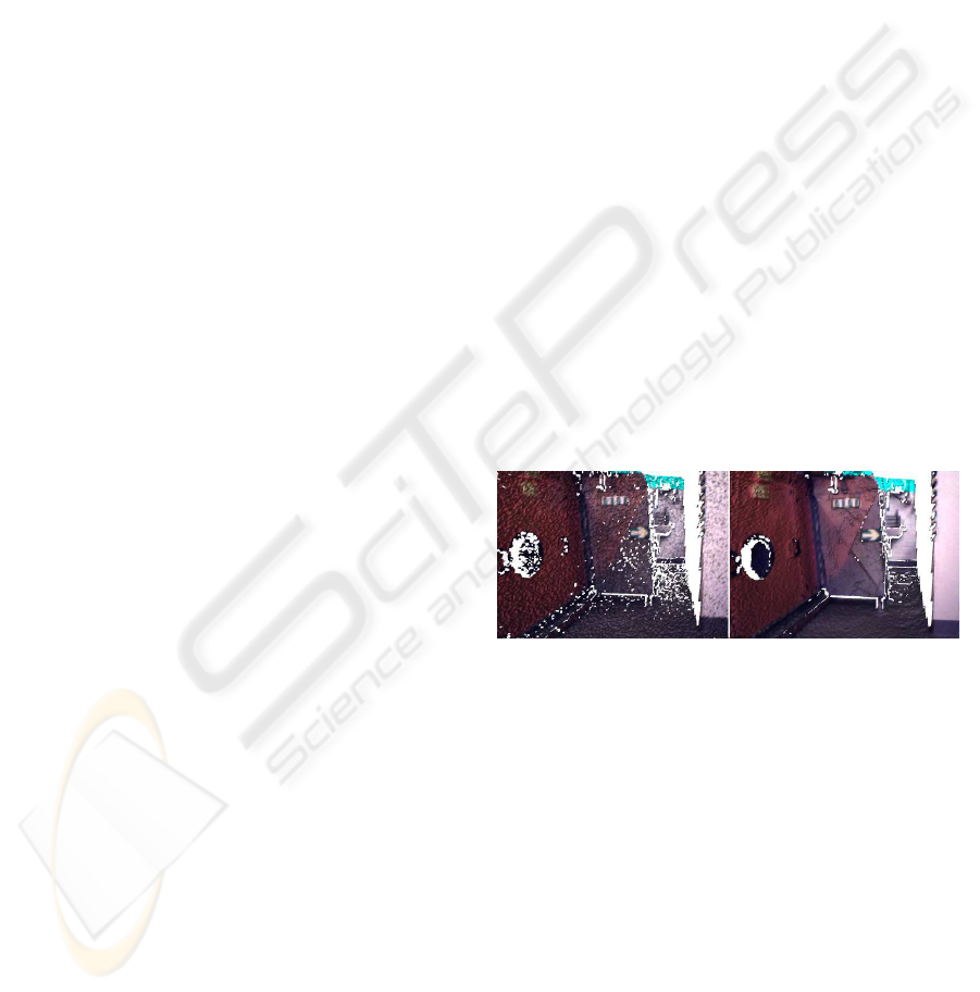
Figure 5: Smoother surfaces with less gaps due to data en-
hancement.
In both scenarios the data enhancement step
proved to be indispensable as it considerably im-
proves the quality of the measured 3D points. Figure
5 illustrates these enhancements. The temporal and
spatial smoothing significantly reduces the number of
gaps of the reconstructed surface. This is important
for the model based tracking because 2D features can
only be tracked where 3D data is available. The re-
constructed surfaces are also smoother than without
the data enhancement step whereas edges are well
preserved.
We overlayed the color image sequences with
the reconstructed 3D model of the scene to evaluate
whether the reconstructed 3D models can be success-
fully used for markerless camera tracking (see figure
6). The camera pose could be successfully tracked in
VISAPP 2010 - International Conference on Computer Vision Theory and Applications
306
both rooms with the reconstructed 3D models and our
model-based camera tracking approach.
Figure 6: Left: Color Image, Right: Color Image aug-
mented with reconstructed 3D model (strongly simplified
mesh).
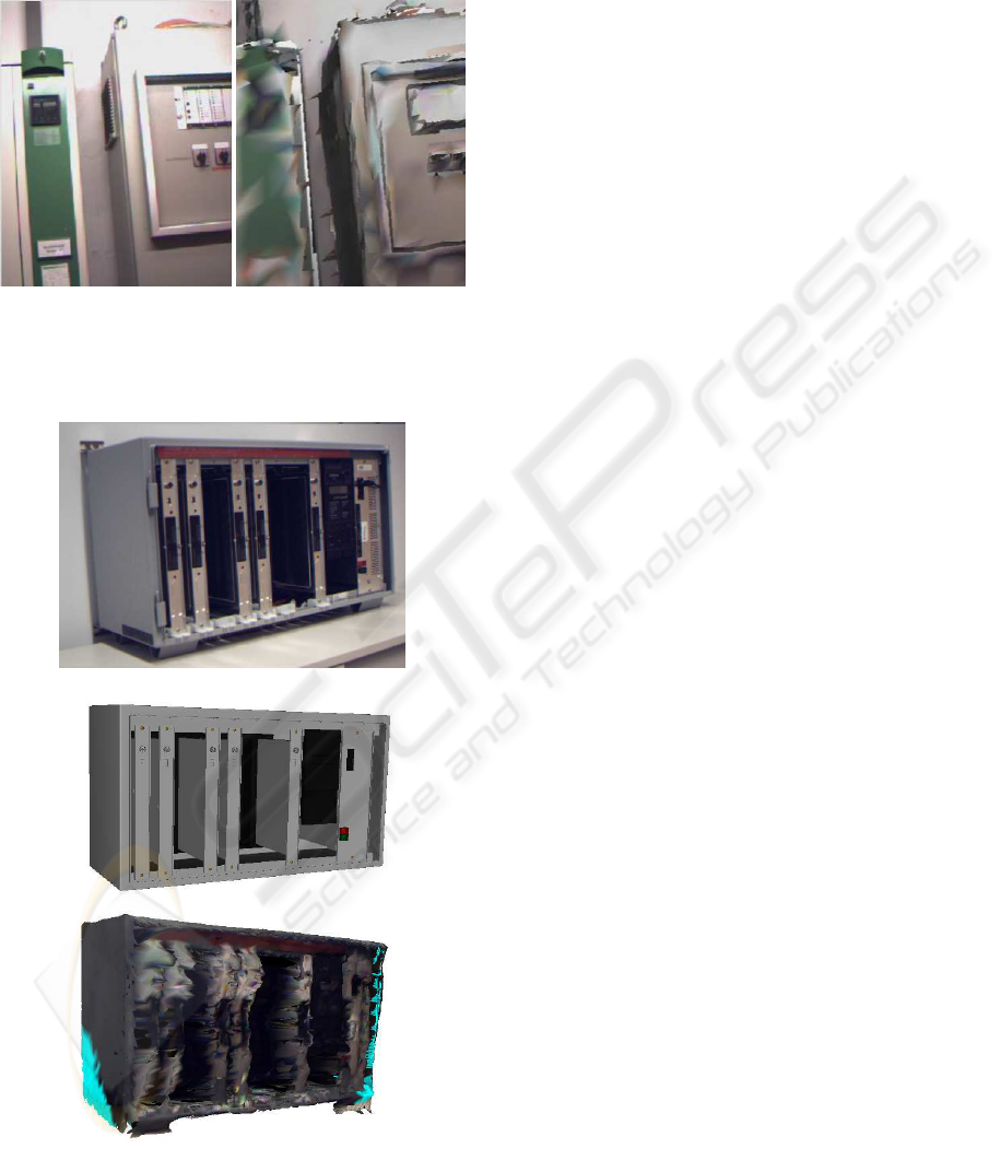
Figure 7: Top: Industrial object with metallic surfaces
which are difficult to measure reliably with a time-of-flight
camera. Center: Reference 3D Model. Bottom: Recon-
structed 3D Model.
6.2 Industrial Object
To evaluate whether our approach can also be used
to reconstruct and track a 3D model of an object
whose 3D acquisition by a time-of-flight camera is
very challenging we reconstructed the industrial ob-
ject of figure 7. Time-of-flight data and color im-
ages taken from five different viewpoints were used
to reconstruct the object. The main challenges of this
object are the metallic surfaces on the front side and
the open slots with metallic side walls inside the ob-
ject by which the light emitted by the time-of-flight
camera gets multiply reflected, resulting in unreliable
and erroneous 3D measurements (see bottom of fig-
ure 7). With an accurate reference 3D model of the
object (center of figure 7) we calculated the error in
the 3D measurements acquired by the time-of-flight
camera. The reference model and the reconstructed
model were aligned with the Iterative Closest Point
algorithm and then both rendered into the z-buffer of
the graphics card with the same virtual extrinsic and
intrinsic camera parameters. By unprojecting the val-
ues of the z-buffer we got a 3D measurement for each
pixel of the two virtual images which we compared to
calculate the euclidean differences between the mea-
surements of the time-of-flight camera and the real 3D
values.
The mean euclidean distance of a view of the front
of the industrial object is 4.3cm. However, the dif-
ferences of the reference model and the reconstructed
model differ a lot dependingon their location. The red
channel of the image in figure 8 shows the euclidean
distances between the reference 3D model and the re-
constructed 3D model. The euclidean distance in cen-
timeters was multiplied with the factor 20 and the red
value of each pixel was interpolated linearly between
0 (black, this means that at this pixel there was no
difference between the reference 3D model and the
reconstructed 3D model) and 255 (bright red, repre-
senting a difference of more than 255/20= 12.75cm).
The differences between the reference model and the
reconstructed model are much higher inside the ob-
ject than at the front part of the object. The pixels col-
ored in blue are measurements where there is a sur-
face of the reconstructed model but not of the refer-
ence model (the base of the object was not modelled
in the reference model). The yellow pixels show parts
where no surface was created in the reconstructed 3D
model due to too big differences between the distance
values of neighboured 3D measurements.
Both the reference 3D model and the recon-
structed 3D model were used for model-based mark-
erless camera tracking as described in section 5. For
this purpose we used a 2D image sequence consist-
ing of 800 frames. The (handheld) color camera was
TIME-OF-FLIGHT BASED SCENE RECONSTRUCTION WITH A MESH PROCESSING TOOL FOR MODEL BASED
CAMERA TRACKING
307
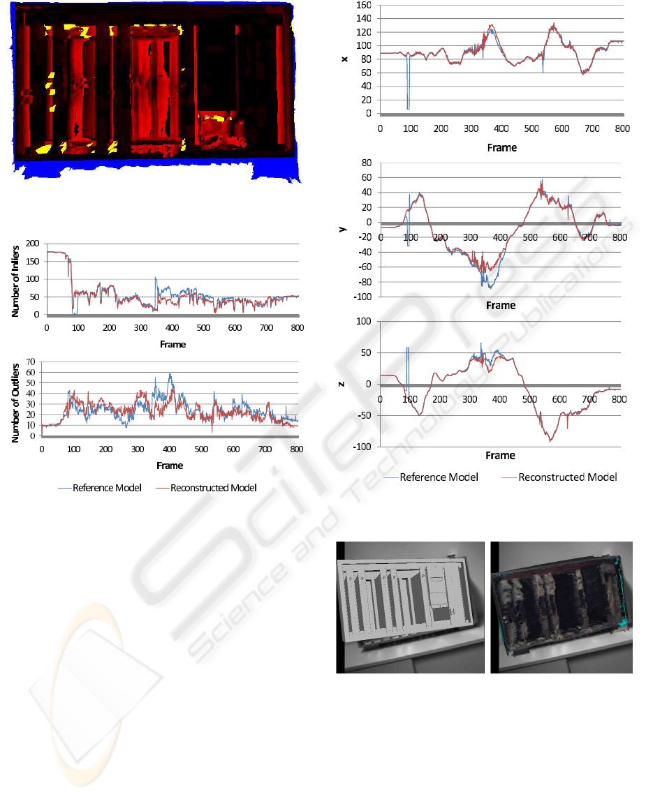
Figure 8: Color encoded differences of the reference 3D
model and the reconstructed 3D model.
Figure 9: Number of tracking inliers and outliers when the
refence model and the reconstructed model are used for
tracking.
moved from a side view of the object around the ob-
ject and back. Figure 9 plots the number of inliers of
the tracked 2D-3D correspondences of each frame as
well as the number of outliers. There are less inliers
in the model based tracking with the reconstructed
model than with the perfect reference model but the
difference is rather small. The industrial object was
successfully tracked with the reference model as well
as with the reconstructed model through the whole
image sequence (see figure 10). With both models
there were several frames in which the augmentation
of the 3D model on the image was not accurate but
with both 3D models the correct tracking was recov-
ered automatically after some frames. There were
also several frames in which the tracking based on the
reconstructed 3D model was more accurate than the
tracking based on the reference 3D model (figure 11).
Figure 10: The camera positions calculated with the refer-
ence model and the reconstructed model.
Figure 11: Frame 343: The reconstructed 3D model is more
accurately tracked than the reference model.
7 CONCLUSIONS
We presented a scene reconstruction approach in
which a time-of-flight camera and a color camera are
combined in a sensor fusion approach to create tex-
tured 3D models of a scene. The 3D data quality is
significantly enhanced by temporal and spatial filter-
ing. Several such colored submeshes are aligned with
VISAPP 2010 - International Conference on Computer Vision Theory and Applications
308

a mesh processing tool. The use of a mesh process-
ing tool has the important advantage that the correct
alignment (which is difficult for 3D measurements ac-
quired by time-of-flight cameras due to the random
and systematic errors in the 3D data) can be super-
vised by a user. Compared to a manual creation of
a 3D model the needed workload is considerably re-
duced. Thus the 3D model can easily be created and
also easily be updated when some parts of the recon-
structed scene change.
The evaluation of our approach shows that the re-
constructed 3D models created with our approach can
successfully be used for model based camera track-
ing. This is even the case for industrial objects with
a metallic surface which are difficult to measure reli-
ably with a time-of-flight camera.
So far the color information is already very useful
for the reconstruction and for the initialisation of the
camera tracking because it is much easier for the user
to supervise a correct alignment of the submeshes if
the texture of the meshes is displayed. In future work
we will extend our approach by using the color infor-
mation of the reconstructed 3D model not only for the
reconstruction step and the camera pose initialization
but also for the frame-to-frame camera tracking.
ACKNOWLEDGEMENTS
This work has been performed within the AvilusPlus
research project granted by the German Ministry of
Education and Research (BMBF). The authors wish
to thank the MeshLab developers and the members of
the Multimedia Information Processing Group of the
University of Kiel for making their MultiCameraCal-
ibration tool and MeshLab publicly available.
REFERENCES
Becker, M., Bleser, G., Pagani, A., Stricker, D., and Wuest,
H. (2007). An architecture for prototyping and ap-
plication development of visual tracking systems. In
Capture, Transmission and Display of 3D Video (Pro-
ceedings of 3DTV-CON 07 [CD-ROM]).
Besl, P. and McKay, N. (1992). A method for registration of
3-d shapes. In IEEE Transactions on Pattern Analysis
and Machine Intelligence, volume 14(2), pages 239–
256.
Bleser, G., Wuest, H., and Stricker, D. (2006). Online cam-
era pose estimation in partially known and dynamic
scenes. In ISMAR 2006: Proceedings of the Fifth
IEEE and ACM International Symposium on Mixed
and Augmented Reality, pages 56–65.
Cignoni, P., Callieri, M., Corsini, M., Dellepiane, M.,
Ganovelli, F., and Ranzuglia, G. (2008). Meshlab:
an open-source mesh processing tool. In Sixth Euro-
graphics Italian Chapter Conference, pages 129–136.
Durand, F. and Dorsey, J. (2002). Fast bilateral filtering for
the display of high-dynamic-range images. In SIG-
GRAPH ’02: Proceedings of the 29th annual con-
ference on Computer graphics and interactive tech-
niques, pages 257–266.
Huhle, B., Jenke, P., and Straßer, W. (2008). On-the-fly
scene acquisition with a handy multi-sensor system.
International Journal of Intelligent Systems Technolo-
gies and Applications (IJISTA), 5(3/4):255–263.
Kolb, A., Barth, E., Koch, R., and Larsen, R. (2009). Time-
of-Flight Sensors in Computer Graphics. In Proc. Eu-
rographics (State-of-the-Art Report).
Lepetit, V. and Fua, P. (2005). Monocular model-based 3d
tracking of rigid objects: A survey. In Foundations
and Trends in Computer Graphics and Vision, vol-
ume 1, pages 1–89.
May, S., Droeschel, D., Holz, D., Wiesen, C., and Fuchs, S.
(2008). 3d pose estimation and mapping with time-of-
flight cameras. In IEEE/RS International Conference
on Intelligent Robots and Systems(IROS), Workshop
on 3D-Mapping.
Oggier, T., Lustenberger, F., and Blanc, N. (2006). Minia-
ture 3d tof camera for real-time imaging. In Percep-
tion and Interactive Technologies, pages 212–216.
Prusak, A., Melnychuk, O., Roth, H., Schiller, I., and Koch,
R. (2008). Pose estimation and map building with a
time-of-flight camera for robot navigation. Interna-
tional Journal of Intelligent Systems Technologies and
Applications, 5(3/4):334–364.
Schiller, I., Bartczak, B., Kellner, F., and Koch, R. (2008a).
Increasing realism and supporting content planning
for dynamic scenes in a mixed reality system incor-
porating a time-of-flight camera. In Proceedings of
the European Conference on Visual Media Produc-
tion, CVMP, volume 5.
Schiller, I., Beder, C., and Koch, R. (2008b). Calibration
of a pmd camera using a planar calibration object to-
gether with a multi-camera setup. In The Interna-
tional Archives of the Photogrammetry, Remote Sens-
ing and Spatial Information Sciences, volume XXI.
ISPRS Congress, pages 297–302.
Shi, J. and Tomasi, C. (1994). Good features to track.
In IEEE Conference on Computer Vision and Pattern
Recognition (CVPR’94), pages 593–600.
TIME-OF-FLIGHT BASED SCENE RECONSTRUCTION WITH A MESH PROCESSING TOOL FOR MODEL BASED
CAMERA TRACKING
309
