
AN AUTOCALIBRATED AND INTERACTIVE TILED DISPLAY
SYSTEM FOR IMMERSIVE EDUCATION
Sung Min Im
Division of Education, College of Liberal Arts, Sookmyung Women’s University
52 Hyochangwon-gil, Yongsan-gu, Seoul, 140-742, Korea
Hyen-Keun Park, Do-Yoon Kim
Withrobot Lab. 4F Dueon Bldg, 1708-6, Seocho-Dong, Seocho-Gu, Seoul, 137-070, Korea
Sang-Youn Kim
Interaction Lab. Advanced Technology Research Center, Korea University of Technology and Education
307 Gajeonri Byeongcheon-myeon, Cheonan, Chungnam, 330-708, Korea
Keywords: Virtual Education, Virtual Reality, Virtual Training, CAVE, Tiled Display.
Abstract: A tiled display is one of virtual reality systems which generate high-quality images and guarantee wide view
angle using multiple projectors. The virtual reality systems may be used as a new educational tool because a
user can be provided immersive sensation as he/she experiences a real object. Previously, we have proposed
a tiled display system where a high resolution image is generated by binding multiple images obtained from
multiple and low resolution projectors. We have also implemented the educational contents on the proposed
tile display system. However, the system does not consider an interaction method which enables an
instructor to control educational contents in front of screen. Therefore, this paper suggests realistic
educational platform based on the interaction and automatic calibration.
1 INTRODUCTION
The emergence of virtual reality technology and its
great improvement have brought immersive
educational platforms (Hereld, M. et al, 1999),
(Yang, R. et al, 2001), (Chen, Y. et al, 2001),
(Hereld, M. et al, 2000), (Krishnaprasad, N. K. et al,
2004). Previously, we have proposed a tiled display
system which has high resolution screen (its
resolution is 4096 x 1536 and its effective resolution
is 3200x1200) (Kim, S. Y. et al, 2009). Moreover,
we have applied a seamless technique to this system
in order to remove joint lines and to improve the
quality of images (Kim, S. Y. et al, 2009). Based on
the previously developed system, we have
implemented education contents for coaching users’
study of a CMOS manufacturing process (Kim, S. Y.
et al, 2009). However, there are some problems to be
solved before accepting educational field. The most
critical problem is that the investigation for
interaction is not thoroughgoing enough. In the
previously system, an instructor controls an
authoring tool on a PC monitor with a mouse during
a lecture. This interaction method makes the
instructor uncomfortable because he/she generally
gives a lecture in front of a screen not a PC monitor.
Therefore, in this paper we propose interactive
education platform where an instructor can move,
rotate, and magnify the educational contents in front
of a screen by pressing and dragging a screen as if
he/she manipulates touch screen. For constructing
this interaction system, we develop a hardware
which is used for recognizing a constructor’s motion
and transferring it to a main PC. Furthermore, we
also present an automatic calibration method for
increasing the quality of educational contents.
90
Im S., Park H., Kim D. and Kim S. (2010).
AN AUTOCALIBRATED AND INTERACTIVE TILED DISPLAY SYSTEM FOR IMMERSIVE EDUCATION.
In Proceedings of the 2nd International Conference on Computer Supported Education, pages 90-93
Copyright
c
SciTePress
2 TILED DISPLAY
2.1 Previously Proposed Tiled Display
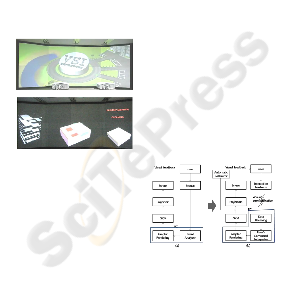
We have already constructed a tiled display system
which provides immersive sensation to users (Figure
1). The system was implemented with a single PC
and 2000 ANSI DLP projectors whose resolution is
1024 x 768. Two graphic cards were included in the
single PC and each graphic card has two graphic
output ports. Each graphic output port has a
Graphics eXpansion Module (GXM) which can
connect two visual displays. Therefore, our system
generates high resolution image by connecting eight
projection areas with a single PC.
Figure 1: Previously proposed system.
The graphic simulations were carried out by a
program written in Visual C++ with direct X. Eight
projectors were used for creating huge and high
resolution images. To look out for the case where
projectors are moved or rotated by a small amount of
disturbance (for example, certain vibration, small
impact, and/or etc.), we purposely overlapped the
portions which the projectors undertook. However,
this installation causes an image to distort. For
compensating this distortion, we have conducted
geometric calibration.
In the previously proposed tiled display system,
we have implemented a virtual silicon island (VSI)
where users can learn semiconductor manufacturing
processes. Users arrived at the VSI and walked in
one of the buildings where they can study the semi-
conductor manufacturing process. We have also
developed a VSI authoring tool in order to easily
create, edit, and play semiconductor contents. A user
can insert or delete the semiconductor
manufacturing components through the VSI
authoring tool. For further information, refer to our
previous research (Kim, S. Y. et al, 2009).
2.2 A Proposed Tiled Display System
for Interaction
In the previously proposed system, a user can create,
edit and play educational contents. However, for
immersive education, students want to investigate a
virtual object by magnifying and rotating the object.
Because of the limited interaction in the previously
developed system, instructors became inconvenience
whenever the instructors wanted to rotate, move, and
translate the educational contents. Therefore, we
developed interaction hardware which recognizes
and analyzes a user’s motion and transfers it to
virtual environment. We attached infrared LEDs to
the interaction hardware and mounted a tracker on a
PC. When a user grasps the interaction hardware and
moves it for transferring his/her command to the PC,
the tracker receives signal from the infrared LED
and recognizes the user’s motion. The signal for
moving is transferred to the data receiving part in the
PC and is interpreted by the command interpreter.
After that, the rendered images are projected on the
screen via GXM and projectors. Therefore, the user
can experience the virtual images as the virtual
images exist in real world. Moreover, a user can
rotate a virtual image in our tiled display with the
interaction hardware. Figures 2 (a) and 2(b) show
the signal flow of previously proposed system and
proposed system, respectively.
Figure 2: (a): Signal flow of previously proposed system
(b): Signal flow of proposed system.
Figure 3 shows the rotated or magnified images.
An authoring tool is displayed in the virtual
environment. That is, the tool is shown on the screen
not a PC monitor. The structure of the authoring tool
AN AUTOCALIBRATED AND INTERACTIVE TILED DISPLAY SYSTEM FOR IMMERSIVE EDUCATION
91
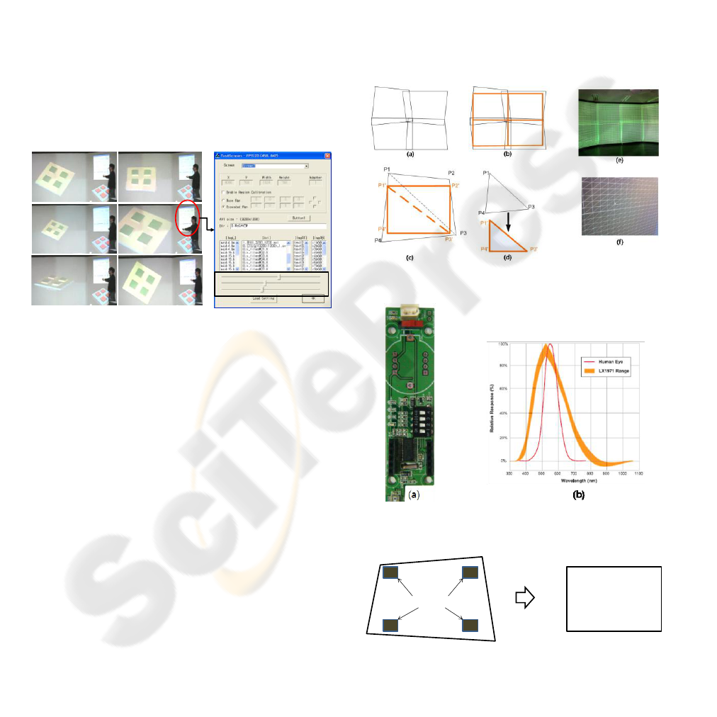
is almost same as that of the previously tool except
for two parts (interaction and automatic calibration
parts). Figure 3(g) shows the authoring tool having
slide bars for interaction. There are three slide bars
for rotations along the x-direction and the z-direction
and for magnifying/minifying the image. If the first
slide bar is moved to the right with the interaction
hardware, the virtual image is rotated along the x-
direction. When a user moves the second slide bar to
the right, the image is rotated along the z-direction.
The third slide bar is for magnifying/minifying the
image. Figures 3(a) and 3(b) show an initial
semiconductor image and the rotated image along
the x-direction, respectively. Figures 3(c) and 3(d)
illustrate the scaled images and Figures 3(e) and 3(f)
are the rotated images along the z-direction. Even
though the screen does not have any touch sensors, a
user can control the authoring tool as the screen has
touch sensor array.
Figure 3: Proposed Interactive and Immersive Platform.
3 AUTO CALIBRATION SYSTEM
In the previously research (Kim, S. Y. et al, 2009),
we have conducted geometric calibration in order to
prevent the distortion of images. We divided original
projection portions and the calibrated projection
portions into triangles as shown in Figure 4 and then
computed transformation matrix. This strategy for
adjusting all nodes manually, however, brought a
new issue for accurate calibration because a user has
to spend a lot of time for calibration process. So, this
paper suggests automatic calibration method by
detecting projection images and addresses the
developed image detector (we call it Wi-gray). Since
the sensitivity of a general camera is different from
that of a human eye, cameras can hardly tell the
difference between the colors or intensities of two
images, however human eyes can. Therefore, it is
very hard to make each intensity of the projection
regions same with a general camera. In order to
adjust the intensities of projection regions, we
developed an image detector whose intensity is
almost same as human eyes.
The objective of the calibration is to adjust a
distorted image (Figure 6 (a)) to a rectangular image
(Figure 6(b)). For calibrating each image
automatically, we attached the image detectors to the
screen and the projected binary code images where
black and white patterns cross in x- and y-directions
as shown in Figure 7. We narrowed the gap between
patterns and accepted the signals from the detectors
to understand the projection region and the position
of the detectors. As such, we could obtain the
relative position between the projection region and
the detector by collecting the intensity about the
binary coded images.
Figure 4: Geometric Calibration.
Figure 5: (a) Image detector (b) the sensitivity curve of
human eyes and the detector.
Figure 6: Calibration of a distorted image (a) to a
rectangular image (b).
(a) (b)
(c) (d)
(e)
(f)
(g)
detector
(a) (b)
CSEDU 2010 - 2nd International Conference on Computer Supported Education
92
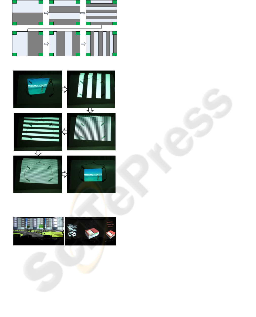
Figure 7: Calibration Process.
Figure 8: The images of before the calibration (a) and after
the calibration (f).
Figure 9: Result after finishing calibration process.
Figure 8 shows the calibration process using the
developed image detectors and the proposed method.
Figure 8 (a) and Figure 8 (f) show the distorted
image and the calibrated image, respectively and
others show the calibration process. Figures 9 (a)
and 9 (b) are the VSI image and semiconductor
educational contents after finishing calibration
process. From Figure 9, we found out that distortion
in educational contents was removed.
4 CONCLUSIONS
In this work, we developed the wireless automatic
calibration system and conducted automatic
calibration process with the system by projecting
gray coded images on the screen. We also presented
interaction hardware system for effective lecture.
ACKNOWLEDGEMENTS
This work was supported by VTRC (Virtual
Training Research Center) in KUT (R-2009-0123).
This work was also supported in part by IT R&D
program of MKE/IITA (2008-F-045-02).
REFERENCES
Hereld, M., Judson, I. R., and Stevens, R.L., 1999.
Introduction to Building Projection-based Tiled
Displays. IEEE Visualization 1999.
Yang, R., Gotz, D., Hensley, J., Towles, H., and Brown,
M., 2001. PixelFlex: A Reconfigurable Multi-
Projector Display System. IEEE Visualization 2001.
Chen, Y., Chen, H., Clark, D., Liu, Z., Wallace, G., and Li,
K., 2001. Software Environments for Cluster-based
Display Systems, IEEE International Symposium on
Cluster Computing and the Grid.
Hereld, M., Judson, I. R., and Stevens, R. L., 2000.
Introduction to Building Projection-based Tiled
Display Systems, IEEE Computer Graphics and
Applications, vol 20(4).
Krishnaprasad, N. K., Vishwanath, V., Venkataraman, S.,
Rao, A.G., Renambot, L., Leigh, J., Johnson, A.E.,
and Davis, B.,2004, JuxtaView - a tool for interactive
visualization of large imagery on scalable tiled
displays, IEEE International Conference on Cluster
Computing.
Kim, S. Y., Park, H. K., and Kim, D. Y., “A Tiled Display
System for Immersive Technology Education”,
CSEDU 2009, pp. 394-397.
Arthur, K. W., 2000. Effects of Field of View on
Performance with Head-Mounted Displays, Master
Thesis, Univ. of North Carolina.
(a) (b)
(c) (d)
(e) (f)
AN AUTOCALIBRATED AND INTERACTIVE TILED DISPLAY SYSTEM FOR IMMERSIVE EDUCATION
93
