
RAPID PROTOTYPING OF 3D ANATOMICAL MODELS TO
HEMODYNAMIC STUDIES
Vania Freitas
Engenharia Biomédica, Instituto Politécnico de Bragança
Campus Stª Apolónia, Apartado 134, 5301-857 Bragança, Portugal
Luís Queijo
1, 2
and Rui Lima
1,3
1
Departamento de Tecnologia Mecânica, Instituto Politécnico de Bragança
Campus Stª Apolónia, Apartado 134, 5301-857 Bragança, Portugal
2
CIBER - Centro de Investigación Biomecánica y Ergonomía
Parque Científico - Universidad de Valladolid, Campus Miguel Delibes – Valladolid, Espanha
3
CEFT - Centro de Estudos de Fenómenos de Transporte
Faculdade de Engenharia da Universidade do Porto, 4200-465 Porto, Portugal
Keywords: Carotid, Rapid prototyping, FDM, TDP, PDMS, Hemodynamics.
Abstract: The purpose of this work is mainly to manufacture several anatomical models in a polymeric material –
polydimensiloxane (PDMS) to study the blood flow through a carotid artery bifurcation. Over the last few
decades, research has been shown that the geometry of the carotid artery is closely related to the
development of serious cardiovascular diseases. Hence, there is a considerable interest in the development
of in vitro experimental techniques able to obtain accurate measurements of the blood flow behavior
through a realistic carotid artery. In this study we decide to apply rapid prototyping (RP) technologies
combined with a PDMS casting technique in order to fabricate an anatomically realistic model of a human
carotid to investigate, in a near future, the effect of the geometry on the local hemodynamics and
consequently improve the understanding of the origin and development of these pathologies. Based on a
human carotid computerized tomography (TC) it has been developed a 3D model through the application of
two rapid prototyping techniques – Fused Deposition Modeling (FDM) and Tridimensional Printing (TDP).
By combining the rapid prototyping techniques with a PDMS casting technique it was possible at the end to
obtain an anatomically transparent model of a human carotid artery made by an elastomeric material, i.e.
PDMS. Hence, we believe that this combination is a promising technique to perform in vitro blood studies
through anatomically realistic models, such as a carotid artery.
1 INTRODUCTION
Large arteries that carry blood out from the heart and
their branches are the most important blood vessels
from human body. These arteries can be classified as
elastic due to their big diameter and predominance
of elastic fibers in their walls. Aortic and carotid
arteries are included in this classification (Williams
and Warwick, 1995).
Cardiovascular diseases are responsible for more
morbidity and mortality than any other disease,
being atherosclerosis, the most common and
significant in a clinic perspective (Collins et al.,
2001). Hemodynamic studies have been shown that
the geometry of the carotid artery produces
favorable conditions for the development of
cardiovascular diseases such as, atherosclerosis and
thrombosis. Hence, it is important to investigate new
in vitro experimental techniques able to obtain
accurate measurements of the blood flow behavior
through anatomically realistic artery models.
In the conversion process of a computerized
tomography in to a 3D model, it is needed a
sequence of cross sections from the studied object.
Using a 3D reconstruction software it is possible to
transform these bi-dimensional images in a three-
dimensional model that can be used to produce a
246
Freitas V., Queijo L. and Lima R. (2010).
RAPID PROTOTYPING OF 3D ANATOMICAL MODELS TO HEMODYNAMIC STUDIES.
In Proceedings of the Third International Conference on Biomedical Electronics and Devices, pages 246-251
DOI: 10.5220/0002787702460251
Copyright
c
SciTePress
solid model in rapid prototyping equipment
(Foggiatto, 2006).
With the objective of obtain a real model from
the anatomical structure a TC image set was used
once this technology was able to provide us the
definition wanted and allowed us to identify the
arteries in the main anatomical area.
After the identification is done, the image
processing starts with the goal to do the artery
segmentation, which means, to isolate the arteries
from the other existent anatomical structures, visible
in the images.
Rapid prototyping technology has been applied
to the previously rendered images in order to obtain
a good quality, low cost and fast manufacture 3D
anatomical model.
After converted into a STL (stereolitography)
file, the 3D digital model is sliced and processed by
the RP equipment that builds the model, layer, by
layer, where each layer is added to the previous one.
In this process we choose two different techniques –
Fused Deposition Modeling (FDM) and
Tridimensional Printing (TDP or 3DP).
Once obtained the wanted tridimensional
structures, these are placed in a molding box to
manufacture the PDMS transparent anatomical
model. This polymer belongs to a group of
organometalic polymers usually known by silicon
and is a biocompatible, transparent, inert, non-toxic
and non-flammable material with a great elastic
effect and, therefore, is used to simulate blood
vessels and other soft tissues.
This structure will allow, in the future,
hemodynamic studies and simulations.
2 EXPERIMENTAL PROCEDURE
2.1 Image Processing
With the objective of obtain a real model from the
anatomical structure a TC image set was used once
this technology was able to provide us the definition
wanted and allowed us to identify the arteries in the
main anatomical area.
After the identification, the image processing
starts with the goal to do the artery segmentation,
which means, to isolate the arteries from the other
existent anatomical structures, visible in the images.
Segmentation process has been performed in the
software ScanIP
®
to where TC images can be
transferred in DICOM format. To do this step,
binarization and thresholding techniques have been
applied to the images in order to obtain a mask in a
range of grey values that includes, in each image, the
tissues from the study object – carotid artery.
By evaluating the type of anatomical structure in
question, the chosen range has been from 204 to
255:
where g(x,y) is the resultant in the image after the
application of binarization technique and f (x,y) is
the image obtained from TC (Alves et al., 2001).
The result after the first iteration has not been
satisfactory due to the existence the other areas in
the same grey range so, in a complementary phase, it
was needed to process each image, pixel by pixel by
removing the structures that were not needed. It was
created a mask to each one of the arteries (right and
left) to allow us to have available, if needed, both of
them.
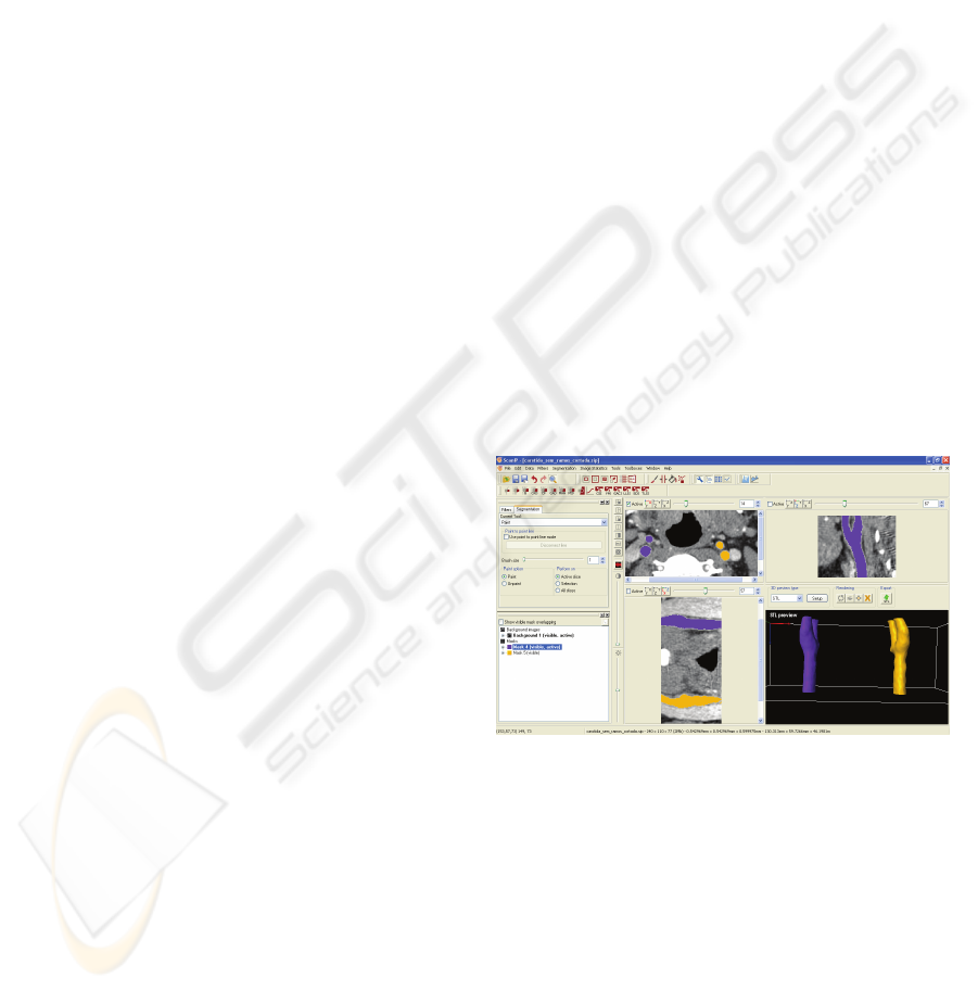
Once concluded artery model finishing by
smoothing all the surfaces, it was kept the main
structure with the bifurcation where most of the
pathologies are developed and erased all the
ramifications that will not make part of this study.
The result can be seen in figure 1 where transversal,
coronal and sagittal plans are illustrated as well as
the 3D rendered model.
Figure 1: Different working plans in ScanIP® software.
When all the image processing phases are
concluded, the file is converted in a STL format file
through internal software translator models and then
processed in printing management software that will
slice the model and allow choosing the printing
parameters to each of the used equipments.
⎩
⎨
⎧
≥
<
=
204),(,255
204),(,0
),(
yxf
yxf
yxg
RAPID PROTOTYPING OF 3D ANATOMICAL MODELS TO HEMODYNAMIC STUDIES
247
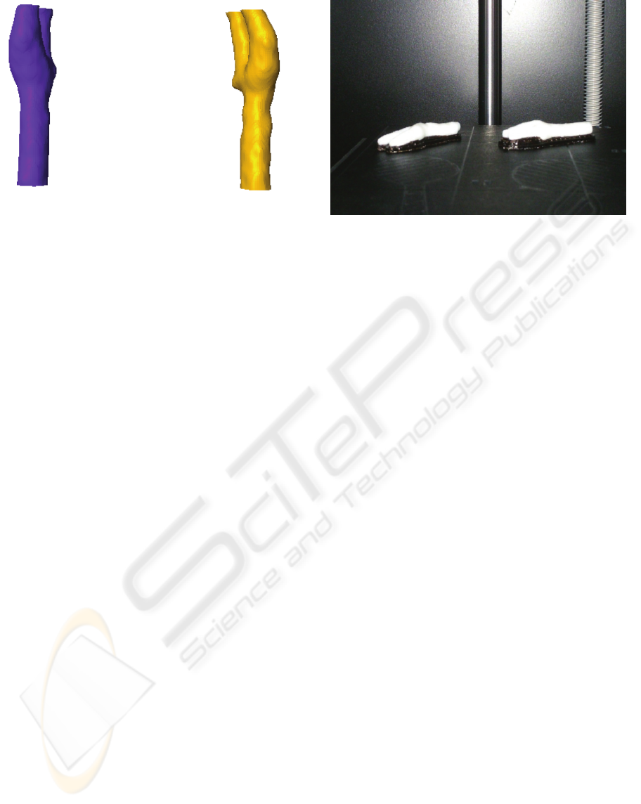
Figure 2: Carotid arteries 3D rendered models.
2.2 Rapid Prototyping
By the STL file conversion into a SLI (slice) format
file we are able to print the model, whatever is the
RP method choosen. This type of file contains the
information to each one of the layers to be printed,
as well to the orientation in which the model should
be printed.
This situation is due to the additive-constructive
characteristic in which the RP processes are based
(Rocha and Alves, 2000).
2.2.1 Fused Deposition Modeling
Fused Deposition Modeling – FDM, builds the
model by extruding ABS polymer filaments through
a printing head. This polymer is heated and melted
when going through the printing head and each layer
is deposited over the previous one melting it,
partially, and becoming a continuous structure.
During work, printing head moves along the
coordinates (x,y) and the depth (z) is obtained by the
platform movement where the model is being
printed.
This process has as particularity the need of use
of a second material as supportive layer where the
main structure doesn’t have any contact with the
previous material layer. The printing head has two
extrusion nozzles to feed, when needed, both
materials in the same layer. At the end of each layer
printing, the working platform is descended in a
distance equal to the deposited layer depth. This
process is made until the entire model is printed.
The model obtained by this process has a good
surface quality and is ready to use after the
supportive material is removed, which is easily
done.
Figure 3: Carotid artery model manufactured by FDM
process.
2.2.2 Tridimensional Printing
In this RP process, the model is built from a
composite dust material (a specific combination of
materials). In printing process, the composite
material is prepared by a cylinder action that flattens
the surface each time a layer is printed. In each layer
the printing head draws the correspondent section in
the material surface in glue aqueous liquid. When
the new material is deposited to the new layer, it is
glued to the previous one by the cylinder action.
Also, in this case, the printing head covers the
coordinates (x,y), being the depth fulfilled by the
movement of the working surface. Each time a layer
is printed the working surface descends and the new
material is deposited maintaining the distance to the
printing head.
All process is repeated until the model is
completely built.
After the model manufacture it is needed to
remove the model from the non-glued material that
can be recycled.
In TDP process, however, some additional tasks
must be performed, once the model surface is dusty
and non-stable. To remove the excess of material not
glued, it is needed to perform a surface cleaning
through the application of a compressed air flow.
Most of cases, to stabilize the surface, it is applied a
layer of cyanoacrylate or epoxy resin (Queijo et al.,
2009).
In this work, two models were printed with
different finished surfaces. To one of them it was
applied one cyanoacrylate layer while the other was
left with unstabilized surface.
BIODEVICES 2010 - International Conference on Biomedical Electronics and Devices
248
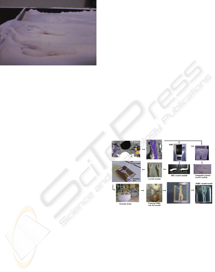
Figure 4: Carotid artery model manufactured by TDP
process.
2.3 Fabrication of PDMS Anatomical
Channels
In vivo animal research is an excellent way of
performing experiments with in environments that
closely mimics the human body. However, in vivo
experiments are laborious, expensive and difficult to
control several parameters and consequently it is
extremely complex to obtain accurate
measurements. On the other hand, by using in vitro
models, besides reducing the number of sacrificed
animals, this kind of models have many other
advantages over in vivo models, such as the ability
to control important parameters, obtain accurate
measurements and reproducible experiments. For
hemodynamic researchers in vitro models have been
extremely attractive as this kind of models allows
systematic flow studies. Hence, many studies on the
blood flow behavior in vitro models have been
performed over the past years. However, most
studies have been done in rigid or simplified models
(Goldsmith et al., 1996)(Lima, 2007). As a result,
there is a need to develop more realistic in vitro
models with geometries and environments that
closely mimics the human body. In this study we
applied two rapid prototyping techniques – Fused
Deposition Modeling (FDM) and Tridimensional
Printing (TDP) combined with a PDMS casting
technique to obtain anatomically realistic models of
a carotid artery.
The PDMS carotid artery was fabricated by
using two kinds of rapid prototyping techniques, i.e.,
Fused Deposition Modeling (FDM) and
Tridimensional Printing (TDP). The main steps for
fabricating the PDMS carotid channel (Figure 5)
were as follows. First, the human carotid geometry
was obtain by computerized tomography (TC) and
then printed by means of FDM and TDP. By
applying the FDM we were able to obtain the carotid
model in a copolymer of acrylonitrile, butadiene,
and styrene (ABS), whereas by using a TDP we
have obtained another kind model in a composite
powder. Next, carotid models with clay supports
where positioned in the bottom of a molding box in
order to pour an elastomeric material into the mould.
Note that, the model obtained by FDM technique
needed to be cut around the branch in order to pull
the model from the casting material without
breaking it. The elastomeric material selected was
the polydimensiloxane (PDMS) due to its
outstanding properties, including good optical
transparency and biocompatibility, easily reversible
sealing to glass, elasticity, replication of fine and
complex geometries, permeable to gases, thermally
stable, and low cost (Lima, 2008). The PDMS
prepolymer was prepared by mixing a commercial
prepolymer and catalyzer (Silpot 184; Dow Corning,
USA) at a weight ratio of 10:1. After removing the
bubbles, created during mixing, by a vacuum pump
the PDMS mixture was poured into the mould
containing the carotid model and then baked into a
oven for about 2 hours at a temperature of about
60°C. Both model and mould with PDMS were then
cooled to room temperature.
Figure 5: Main steps to fabricate PDMS carotid channels.
The embedded carotid model manufactured by
the FDM technique was pulled out of the PDMS and
as result it was possible to obtain an anatomically
transparent model of a human carotid artery (see
Figure 6). From Figure 6 it is possible to observe
that the PDMS carotid model seems to have enough
good transparency able to perform blood flow
visualization studies. However, should be pointed
out that walls of this PDMS carotid model have high
levels of roughness due to the rapid prototyping
technique (FDM) used to manufacture the ABS
carotid model. In a near future, we are planning to
polish the surface of the ABS carotid model to
decrease roughness of the model.
RAPID PROTOTYPING OF 3D ANATOMICAL MODELS TO HEMODYNAMIC STUDIES
249
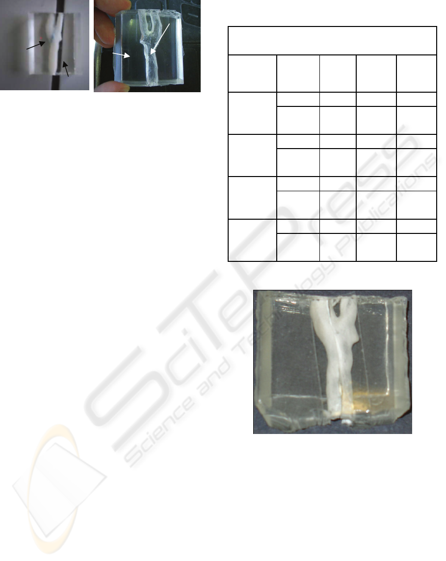
Figure 6: a) ABS carotid model manufactured by the FDM
technique embedded in PDMS; b) PDMS carotid channel
by means of a FDM technique.
For the case of the carotid model manufactured
by the TDP technique it was not possible to pull out
from the PDMS due to the extremely fragile
characteristics of the composite powder. Hence, we
decided to examine the solubility of several solvents
in both PDMS and TDP carotid model in order to
determine the most suitable solvent able to dissolve
the embedded carotid model without significantly
modifying the physical properties of the PDMS. In
this study we used four kinds of solvents, i.e.,
acetone, hydrochloric acid (HCl), sodium hydroxide
(NaOH), petroleum ether (PET). Table 1
summarizes the most relevant results obtained by
using the selected solvents. Generally, we used 8 test
tubes : 2 with acetone, 2 with HCl, 2 with NaOH and
2 with PET. For each solvent we have immersed a
small piece of PDMS and the composite powder
used to fabricate the carotid model by means of the
TDP. First, both solutes were weighted before the
immersion into the solvent. After 24 hours, the
samples were first inserted into an ultrasound
machine for 15 minutes and then into an oven for 4
hours at a temperature of 60ºC. Finally, by means of
a vacuum pump the remaining water was completely
removed from the samples and ready to be weighted
once again. After 48 hours, this process was
repeated once again and as a result we could obtain
the data presented in Table 1.
The results from Table 1 show that the
hydrochloric acid (HCl) has the highest solubility
followed by the sodium hydroxide and the petroleum
ether. Hence, we decided to immerse the PDMS
containing the carotid model into hydrochloric acid
(HCl). Although most of the solute was dissolved we
have also observed that small amount of the
composite power was still attached on the wall of the
carotid channel and it was extremely difficult
remove them from the walls (Figure 7). These
preliminary observations show that this technique
still needs to be improved in a near future.
Table 1: Experimental results obtained for four different
kinds of solvents.
Experimental results
Solvent Solute
Initial
weight
(g)
Weight
after
24 hours
(g)
Weight
after
24 hours
(g)
Acetone
PDMS 0.2578 0.2488 0.2488
TDP
carotid
model
0.3361 0.3195 0.3128
Hydrochloric
acid (HCl)
PDMS 0.3476 0.3449 0.3448
TDP
carotid
model
0.2214 * *
Sodium
hydroxide
(NaOH)
PDMS 0.3643 0.3642 0.3640
TDP
carotid
model
0.2022 0.1274 0.1110
Petroleum
ether (PET)
PDMS 0.2155 0.2040 0.2430
TDP
carotid
model
0.2620 0.2043 0.2025
* All the solute was completely dissolved in the
given solvent.
Figure: 7: PDMS carotid channel by means of a TDP
technique.
3 CONCLUSIONS
The main objective consisted in applying two kinds
of rapid prototyping technologies to manufacture
several in vitro carotidal anatomical models in
PDMS polymer for posterior hemodynamic studies.
The conclusions drawn from this work can be
resumed as follows:
It was possible to conciliate several rapid
prototyping techniques to obtain PDMS
anatomical models;
PDMS
Blue
clay
PDMS
Carotid
channel
BIODEVICES 2010 - International Conference on Biomedical Electronics and Devices
250
Rapid prototyping technology has proven that is
a useful technology in the fast manufacture of
good quality anatomical models from medical
images, providing the ability of obtaining
complex human structures that would very
difficult to obtain by other means;
The model obtained by using a FDM technique
has shown the best surface transparency to
perform in vitro blood flow visualization
studies.
4 FUTURE DIRECTIONS
The PDMS transparent models obtained by the FDM
technique seems to be promising way to perform in
vitro blood flow studies through anatomically
realistic replica of a human carotid artery bifurcation
made by PDMS. Currently, an ongoing study to
perform flow measurements trough the PDMS
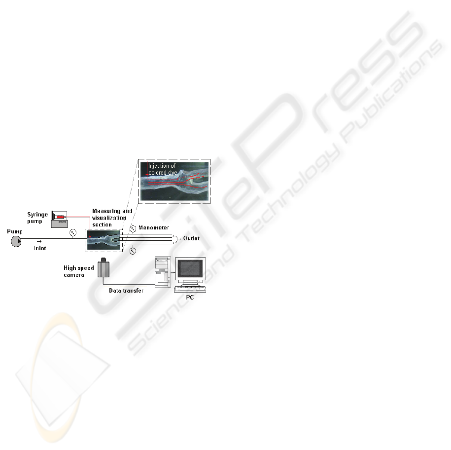
carotid models is currently under way. Figure 8
shows the experimental set-up that we planning to
use to perform those studies.
Figure 8: Experimental set-up to perform in vitro flow
visualizations through the fabricated PDMS carotid
channels.
ACKNOWLEDGEMENTS
The authors would like to thank Mr. Bruno
Magalhães and Dr. João Carlos Noronha, from the
Krug Noronha Clinic, for providing TC images and
also Dr. António Pontes and Mr. Miguel Queirós,
from Minho University, for supplying some ABS
carotid models tested in this work.
REFERENCES
Alves, Fernando; et al., 2001. Prototipagem Rápida.
Protoclick, Porto.
Collins, Tucker, Robbins, Stanley L., Cotran, Ramzi S.,
Kumar, Vinay, 2001. Fundamentos de Robbins -
Patologia Estrutural e Funcional, Guanabara Koogan.
Brasil, Sexta edição.
Foggiatto, J. A., 2006. O Uso da Prototipagem Rápida na
Área Médico-Odontológica. Tecnologia &
Humanismo, 60-68.
Goldsmith, H., Turitto, V., 1986. Rheological aspects of
thrombosis and haemostasis: basic principles and
applications. ICTH-Report-Subcommittee on Rheology
of the International Committee on Thrombosis and
Haemostasis. Thromb Haemost. 55(3), 415–435
Lima, R.. et al., 2007. In vitro confocal micro-PIV
measurements of blood flow in a square microchannel:
the effect of the haematocrit on instantaneous velocity
profiles. Journal of Biomechanics, 40, 2752-2757
Lima, R., et al., 2008. In vitro blood flow in a rectangular
PDMS microchannel: experimental observations using
a confocal micro-PIV system. Biomedical
Microdevices, 10(2),153-67
Queijo, Luís, Rocha, João, Barreira, Luísa, Pereira, Paulo
Miguel, Barbosa, Tiago, San Juan, Manuel, 2009. A
surgical training model manufacture using rapid
prototyping technology. Innovative developments in
design and manufacturing – Advanced Research in
Virtual and Rapid Prototyping, Taylor & Francis.
Rocha, J. & Alves, L., 2000. Utilização de moldações
cerâmicas compósitas no fabrico de ferramentas
metálicas. 2º Encontro nacional do colégio de
engenharia mecânica da ordem dos engenheiros.
Coimbra. Portugal.
Williams, P.L, Warwick, R., 1995. Gray’s Anatomy,
Churchill Livingstone. Edinburgh, 38
th
Edition.
RAPID PROTOTYPING OF 3D ANATOMICAL MODELS TO HEMODYNAMIC STUDIES
251
