
USING SPREADSHEETS TO TEACH COMPUTER ARCHITECTURE
Claude Timsit and Soraya Zertal
PRiSM laboratory, Versailles University, 45 Av. des ´etats unis, 78000 Versailles, France
Keywords:
Hardware simulator, Computer architecture learning, Spreadsheets.
Abstract:
In this paper, we introduce a new tool dedicated to computer architecture learning. Based on spreadsheets, it is
simple to use and widely portable. It provides a set of spreadsheets with examples to run and analyse and gives
the oppurtinity to users to build their own basic circuits from transistors and basic gates to logic and clocked
blocks. Users can also use the provided machine spreadsheet to write their assembly code, execute it and even
enhance the instructions set by adding new instructions and their associated microcode to the microcode table.
The results are very promising considering the speed and the level of the understang of the students following
the computer architecture design course since the introduction of this tool.
1 INTRODUCTION
Computer architecture: binary coding, circuits de-
sign and assembly programming are not obvious to
understand for a complete neophyte in the area. It
makes this subject very difficult to teach and needs
some pedagogic and simple to use tools to make this
task easier, in which the beginner who has never pro-
grammed in his life should acquire very easily and by
himself the full knowledge of the different tools as
well as the skill of testing his own modifications in
order to fully understand the underlying ideas.
For more advanced and more convinced users, a digi-
tal design may be specified by its behavioral or struc-
tural description and tested after some compilation
(using VHDL, Verilog or other programming lan-
guages as Java, C, C++, SystemC).
In order to fit with the competences of our students
the only possible ways to interface with the computer
were either the video game like approach, which in
our point of view does not fix knowledge (yet another
game), or spreadsheet like formulas in which they are
obliged to understand and describe the relationship
between signals. We have introduced a new method
for teaching the bases of logic design and computer
architecture for beginners three years ago, and since
then we are using it for undergraduate students. Our
method is based on a series of simulators realized us-
ing classical spreadsheets, progressively modified by
the students without any kind of classical program-
ming (in terms of high level language).
2 RELATED WORK
Many tools have been used in order to help computer
architecture teaching. They are usually either full non
portable CAD commercial and non commercial ap-
plications, very rich but needing quite a lot of time
for tool learning. Another portable way is the Java
based applets concept (Hades and the related frame-
works (Hendrich, 2000), (Hendrich, 2002) and (Fer-
reira et al., 2005), as well as Opar (Guyot, 2005)
for instance). The trouble with this kind of tools in a
teaching approach is that: ”While eye catching an-
imations easily impress one-time users, it is much
more difficult to make them really helpful for teach-
ing”, at least for the beginner (Hendrich, 2000).
We have used the Diglog module (Lazzaro, 2000)
dedicated to circuit and logic simulation which is
a part of chipmunk, developed by J.Lazzaro from
Berkeley University-CA.This software provideselec-
tronic computer aided design tools for Schematic cap-
ture, circuit and logic simulation, VLSI layout and
LVS, data viewing and drawing
1
. It provides a rich
gates and basic circuits library but we noticed that
the design of logic blocks and the connection between
them became quickly a laborious task, due to the lack
of ways to connect simply parallel busses. (In fact,
connexions, inputs and outputs are made only at the
bit level). Building the simplest machine needs a hard
work, error prone and very difficult to achieve in a
1
It can be downloaded at: www.cs.berkeley.edu/ laz-
zaro/biblio/software.html
101
Timsit C. and Zertal S. (2010).
USING SPREADSHEETS TO TEACH COMPUTER ARCHITECTURE.
In Proceedings of the 2nd International Conference on Computer Supported Education, pages 101-105
DOI: 10.5220/0002781401010105
Copyright
c
SciTePress

very limited time.
A very few experiments have been done using spread-
sheets (A.El-Hajj et al., 2000; Smith, 2007; Seila,
2004) in which very often the spreadsheets are used
primarily as a way of displaying preprogrammed
blocks written in Visual Basic or its equivalent.
The proposed approach requires only a basic un-
derstanding of spreadsheets formulas use which is
considered as well known by all the students. The
main objective is to provide on each spreadsheet all
the elements necessary to understand the working of
each part by a direct access to the formula. A stu-
dent can access to everything, verify, modify and test
each part or the whole of a simulation. The main idea
is that absolutely nothing is hidden. Every component
being described by a visiblefunction or by a few func-
tions, a misunderstanding can only be a misreading of
a function.
3 COURSE AND TOOL
ROADMAP
The content of the course is based on the classical
hierarchy of any computer architecure course. The
practical (lab.) works use our simulators realized
using spreadsheets with no programming (at the VBA
or other level).
At least, one spreadsheet is dedicated to every
chapter and allows to construct, check and validate
a piece of hardware related to the chapter. The course
covers the following chapters :
1. From the transistor to the gate provides a
spreadsheet with a bunch of transistor based cir-
cuits for basic gates and the possibility to change
their input values or parameters to observe and an-
alyze the analog and digital signals.
2. Making functional blocks with gates and reg-
isters provides a spreadsheet containing gates,
some digital circuits examples which will be used
to construct functional blocks.
3. The Von Neuman computer approach, the data
and the control paths are detailed and illustrated
by a basic operational machine on a spreadsheet.
4. Study of a first simplistic microcoded machine
provided with both a simple code in memory and
the details of the microcode. The students can use
it to launch an execution at a micro instruction
level.
5. Enhancing the microcode by defining new in-
structions and their associated micro instructions
sets inspired by the initial instruction set mi-
crocode.
6. Assembly coding for simple problems, to load
and execute on the provided machine spreadsheet.
For this purpose we use both a manual assembly
method and an external C written assembler.
7. New addressing modes as indirect and indexed
are developed
8. Subroutines : making a software stack a branch
and link instruction is detailed, as well as the way
of handling a software stack.
9. I/O handling and interrupts A simple interrupt
logic is created and is associated to direct I/Os.
4 DEVELOPING MACHINE
SIMULATORS USING
SPREADSHEETS
The use of spreadsheets to make logic simulations or
CPU simulations is not new and we can cite (A.El-
Hajj et al., 2000) and (Seila, 2004) as two good exam-
ples of what can be done, by the use of a VBA pro-
gramming. Nevertheless, this type of realization has
two drawbacks: it is hardly portable from a spread-
sheet to another (for instance from EXCEL to Open
Office Calc) and the fact that macros hide a lot of in-
formations to the students.
We believethat using only formulas which are vis-
ible at anytime is much more educative even if the
work is a little bit harder to prepare. In this tool, each
input or output of an element (transistor, resistor, gate
or logic block) is associated with a cell. The inter-
connects between elements are done at two levels:
the component functional level and the components
interconnection level. At the component functional
level, the input of every element needs the address
of the output of the previous one to ensure a correct
execution of the implemented function by using the
right parameters. At the components interconnection
level, lines representing physical links can be imple-
mented either by hand drawing, or by the use of the
”trace precedent” function which exists at least in Ex-
cel and OpenOffice. It draws automatically a straight
line from the input to the previous output. Using such
a method, the student can simulate a circuit the level
he wishes (analog, binary or digital bus value for in-
stance).
CSEDU 2010 - 2nd International Conference on Computer Supported Education
102
4.1 The Analog and Digital Points of
View
During many years of logic and architecture teach-
ing, we have understood that the students have a real
problem to see the link between an analog signal and
a digital one. The first part of the course is intended
to show how simple is a NOT and a NOR gate be-
havior. This is achieved assuming simple transistor
models at a static level. The analog and digital views
of some gates are shown by testing and modifying the
different parameters of the electronic circuit as charge
resistors, number of inputs etc.. in order to show for
example what should be a level margin and to what
extent a noise can be harmful to a circuit.
The simulator is based on the Ohm law which has
been very easily transposed on a spreadsheet. The
students have a clear view of the different intensities
and voltages, and are allowed to modify the charge
resistors, the transistors characteristics and so on.
Figure 1: Simulation of simple gates using transistors.
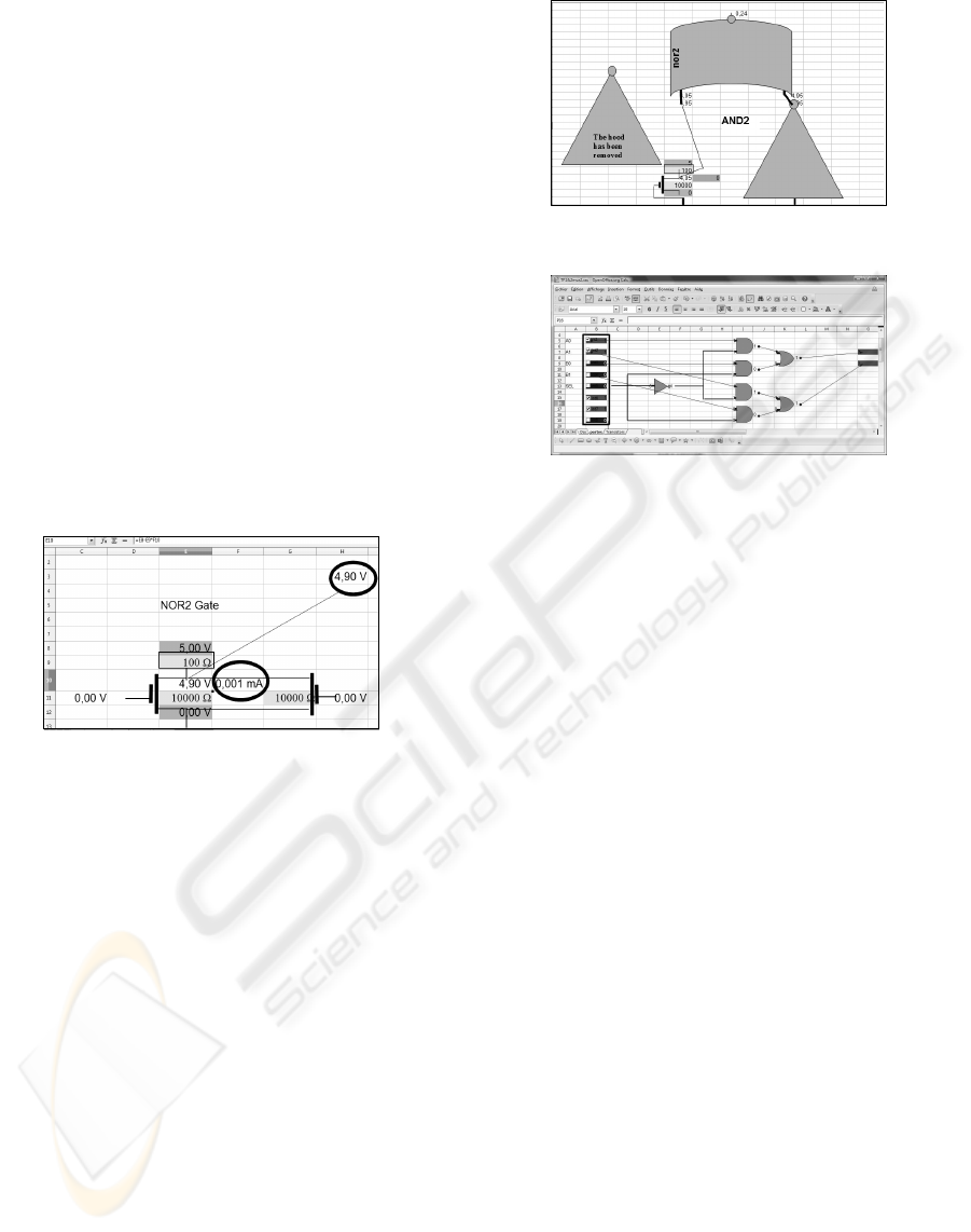
4.2 Gates Realization
The second step is dedicated to the realization of other
gates, and of small combinatorial logical blocks. We
assume in this step that the inside of the gate has been
understood and that we can work now at the logic
level. During the associated lecture, Boolean algebra
and Boolean identities are explained, and a few ex-
amples of Karnaugh optimizations are illustrated by
some basic examples as the one bit full adder.
A spreadsheet containing switches, leds and many
classical gates is given. The students can duplicate
and move the gates and leds and are able to assess
their logical equations by simulation. In order to
make the spreadsheet operational for this kind of sim-
ulation, it is compulsory to let the spreadsheet to be
recursive. In fact, the order of the calculations ap-
plied to the different cells is not needed but it is very
important to keep the spreadsheet portable.
The very first exercises is dedicated to the verifi-
cation of the first De Morgan’s law. Typical practical
circuits as a four bit adder and a two input multiplexer
Figure 2: Under the hood : The AND2 gate.
Figure 3: Example of a 2bits 2 inputs multiplexer.
(see figure 3) are built and checked. Next, we intro-
duce on another sheet the use of clocked logic: this is
simulated by a phased clock.
4.3 Simulation of Clocked Components
In our following models, all the combinatorial parts
are simulated during one phase, while all clocked el-
ements (registers, memories during the writing phase,
counters etc.) change their internal values only during
another phase. This is fully explained in the tutorial.
The first typical example given is a loadable counter.
Its circuit is composedof an adder, a multiplexerand a
register, all of them previously explained. The inputs
of this counter are A (a loadable value), Clear (asyn-
chronous input), IN (mode selection load/increment),
and ck (the clock). The output of the counter is called
Output, the output of the adder is called SADD,the
output of the multiplexer SMUX, and the internal
value of the register Reg.
This leads to the following set of equations (see
figure 4):
Reg = if(Clear = 0if(ck = 1;SMUX;Reg);0) (1)
which is applied to cell G7
SMUX = if(IN = 1;A;SADD) (2)
which is applied to cell E7
Output = if(ck = 0;Reg;Output) (3)
applied to cell H7
SADD = Output + 1 (4)
USING SPREADSHEETS TO TEACH COMPUTER ARCHITECTURE
103
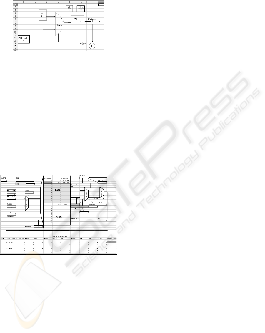
Figure 4: Example of a loadable counter.
applied to cell G18.
The equations Output for instance being recursive,
it is compulsory to authorize recursion.
4.4 Micro Code Definition
The Von Neuman model is fully detailed during the
tutorial. A very simple instruction set for a one regis-
ter machine using only immediate and direct address-
ing modes is explained. Then a data path is proposed,
and the sequences of the different control bits are de-
fined. All those bits are put in a table for each micro
instruction step, which leads to the definition of a mi-
crocode as illustrated by figure 5.
Figure 5: A basic datapath and microcode.
During the lab’s work, a spreadsheet showing the
data path and the microcodes of a very few instruc-
tions is given. The data path connects a memory
(PROM and RAM), a program counter, an instruction
register, a simple ALU, an address memory register
as well as a few multiplexers. All the elements are
connected via a data bus and an address bus. Each of
the components is controlled by a micro instruction
field, the instantaneous value of which is duplicated
near by its compnent in order to make the view more
readable. In order to simplify the micro code inter-
pretation, each ins truction is divide in two or three
micro instructions, i.e. the decode and one or two exe-
cute. To help the students the conditionnal formatting
of the cells is used to show what microprogram line
and main memory word are currently accessed. The
first work asked from the students is to fully under-
stand the way the data path is realized and to check at
the microcycle level its behavior. The two most im-
portant issues are:
1. The Micro Instruction Address Calculation:
The micro instruction address calculation is a bit
complex and in our experience always needs the
help of the lecturer. It needs the knowledge of the
instruction rank in the microcode list and the way
instructions are coded. The memory cells are sim-
ulated in a spreadsheet, giving to each the respon-
sibility of its internal value. Thus, each memory
cell has to check if the memory address bus car-
ries its own address, if the write enable is active
and if the number of the microcycle corresponds
to the write phase.
2. Design of New Instructions:
the student is asked to unprotect the spreadsheet
and to create his own first instructions. In the
beginning, these will be very simple: changing
the executed arithmetic operation from ADD to
SUB or changing the addressing mode for a given
instruction from immediate mode to direct mode
for instance. The correctness of the developed in-
struction will be tested at the microcycle level.
At this level the structure of an assembler is pro-
posed during the tutorial and this structure is used
to write an assembly code using a simple loop for
instance. The aim of this operation is to show ex-
actly how an assembler works (two passes, sym-
bol table, effect of the classical directives). In
order to help the students, an assembler in C
and its executable versions are given (Motorola
like). Then the students introduce an index reg-
ister which is added to the data path. New instruc-
tion as well as indexed addressing modes are im-
plemented and tested.
In some instances, the simulator is modified by the
student, in others when there is a lack of time left, a
version of the simulator is ready to use. Another ver-
sion allowing the implementation of a software stack,
as well as the hardware necessary to store the return
address is proposed to introduce and fully understand
the way subroutines are handled.
4.5 I/O and Memory Realization and
Interrupts Implementation
A very simple version of I/O block using a memory
mapped system allows to read and write values and to
handle ASCII values, with which a lot of interesting
CSEDU 2010 - 2nd International Conference on Computer Supported Education
104

exercisescan be built. The architectureis then slightly
modified in order to show by simulation a very simple
interrupt system. (Use of an interrupt flip flop and its
commands, and of an interrupt vector address).
5 CRITICAL DISCUSSION
The use of other hardware CAD tools needs quite a
long training (at least 20 hours for people already ac-
quainted with at least one programming language).
The proposed use of spreadsheets needs only a train-
ing of a few minutes for students used to formulas in
spreadsheets. Nevertheless, the hardware which can
be simply tested by this method is restricted to small
machines, whose entire microcode and circuits could
be contained in one or two sheets. This is fully suf-
ficient for undergraduate courses, but limits its use.
Another criticism is that although the first realiza-
tions were very simple and very fast to achieve. Only
one author made the first version of a Von Neuman
machine in one week end. It has been more diffi-
cult to make it portable between different versions of
EXCEL, and even more to be also compatible with
OpenOffice Calc. The evaluated cost for the whole
methodology development including a parametrized
assembler is of about three men months.
6 CONCLUSIONS
This methodology of teaching seems to be very ef-
ficient: at every step of a hardware component de-
sign, it mixes deductive approaches with inductive
approaches. The student is given laws, for instance
Ohm law, from which he derives the understanding of
a simple gate. This method has been experimented
now for 3 years on about 400 students and gives very
good results. The time allocated to practical works is
very short (12 or 18 hours). At the end, every student
has at least fully understood a data path, a control path
and different addressing modes. The result is much
better than what we got with the same lab’s time, from
Diglog for instance, where the students spent all their
time in connectingthe wires, and where only one third
of them were able to fulfill and test a very simple ma-
chine.
This first course in computer architecture has demon-
strated that it greatly simplifies the learning of both
C language, operating systems and compiling tech-
niques. As a future extension, a book on the method-
ology including exercises is being written and will be
available soon at Hermann Editor.
REFERENCES
A.El-Hajj, Kabalan, K., and Mahmoud, S. E.-H. (2000).
An improved spreadsheet toolbox for simulating dig-
ital networks. Computer Applications in Engineering
Education, 9(2):78–86.
Ferreira, R., Beck, A., Carro, L., Toledo, A., and Silva, A.
(2005). A java framework to teach computer architec-
ture. International Federation for Information Pro-
cessing IFIP, (192):25–36.
Guyot, A. (2005). Opar: notes and exer-
cises of arithmetic in java. http://users-
tima.imag.fr/cis/guyot/Cours/Oparithm/english.
Hendrich, N. (2000). A java-based framework for simu-
lation and teaching. In 3rd European Workshop on
Microelectronics Education.
Hendrich, N. (2002). From cmos-gates to com-
puter architecture: Lessons learned from five years
of java-applets. http://tams-www.informatik.uni-
hamburg.de/paper/2002/ewme2002/five.pdf.
Lazzaro, J. (2000). Chipmunk software.
http://www.cs.berkeley.edu/∼lazzaro/biblio/
software.html.
Seila, A. F. (2004). Spredsheet simulation. In Proceedings
of the winter Simulation Conference.
Smith, R. E. (2007). A spreadsheet-based simulation for
cpu instruction execution. In Proceedings of the ASEE
Annual Conference.
USING SPREADSHEETS TO TEACH COMPUTER ARCHITECTURE
105
