
SELF-DESTRUCTION PROCEDURE FOR CLUSTER-TREE
WIRELESS SENSOR NETWORKS
Madalin Plastoi, Daniel Curiac, Ovidiu Banias, Constantin Volosencu, Dan Pescaru
Politehnica University, Timisoara, Romania
Alex Doboli
University of New York, Stony Brook, New York, U.S.A.
Keywords: Wireless sensor networks, Self-destruction, Cluster-tree topology.
Abstract: Wireless sensor networks (WSN) are rapidly expanding their attractiveness in both military and civilian
applications, imposing the need for effective security strategies/mechanisms. In this paper we considered
that a new phase (self-destruction) must be included as a final stage in the WSN lifecycle in order to assure
the confidentiality regarding information like: network topology, type of measurement data gathered by
sensors, encryption/authentication algorithms and key-exchange mechanisms, etc. that can be unveiled
through reverse engineering methods. Moreover, we presented a new procedure that implements this new
lifecycle phase on a cluster-tree network topology.
1 INTRODUCTION
A wireless sensor network is an assembly of sensor
nodes that is able to observe diverse physical
phenomena. Operating in harsh environments and
sometimes dealing with sensitive data, implies the
use of specific and efficient security mechanisms.
Attacks based on structural weakness like selective
forwarding, Sybil, wormhole, sinkhole, etc. (Karlof,
2003) can be avoided by a set of measures based on
cryptography, adequate network topology choice
and proper routing mechanisms selection.
From all categories of attacks against security
within WSN, the most dangerous attack looks to be
the node-capturing attack (Curiac, 2007), which can
be performed even after its operational phase of its
lifecycle, when the nodes are abandoned in the field.
In this case, the attacker has access to a large
quantity of nodes and through reverse engineering
techniques he can obtain information regarding the
purpose of the WSN deployment in that area, the
network topology, the type of measurement data
gathered by sensors, the encryption/authentication
algorithms and key-exchange mechanisms, etc. To
avoid this type of attacks, a new strategy has to be
built. This paper solves this problem by
reconfiguring the traditional WSN lifecycle in order
to response efficiently to this kind of threats.
Based on different approaches about WSN
lifecycle (Dohler, 2008) (Steffan, 2005), which
suggest that the WSN lifecycle has to be divided into
four stages: a) Pre-birth: design, implementation,
testing; b) Birth: deployment, (self-) organization,
configuration, optimization, validation, etc.; c) Life:
operation, maintenance, (self-) healing; and d)Death:
node failure, breakdown in connectivity, etc.; we
decided to introduce a new phase - self-destruction,
in order to preserve sensitive information after the
death stage. In our view, self-destruction is defined
as the lifecycle phase in which the WSN is partially
or totally destructed based on a deliberate decision
taken by the WSN itself.
2 SELF-DESTRUCTION
METHODOLOGY
The IEEE/ZigBee 802.15.4 standard (Ergen, 2004)
is providing low energy consumption over oriented
topologies: star, mesh and cluster-tree. For
implementing the self-destruction phase of the WSN
63
Plastoi M., Curiac D., Banias O., Volosencu C., Pescaru D. and Doboli A. (2009).
SELF-DESTRUCTION PROCEDURE FOR CLUSTER-TREE WIRELESS SENSOR NETWORKS.
In Proceedings of the International Conference on Wireless Information Networks and Systems, pages 63-67
DOI: 10.5220/0002229200630067
Copyright
c
SciTePress

lifecycle, we assumed a cluster-tree topology (Figure
1).
Figure 1: Cluster-tree wireless sensor network.
Every network cluster follows a well-defined tree
pattern formed of the following components: i) the
PAN (Personal Area Network coordinator) node at
the “zero” level; ii) the FFD nodes (Fully Functional
Device – sensing and routing or routing only) for
middle levels; and iii) optionally RFD nodes
(Restricted Functional Device – sensing only) as tree
leafs for ending levels (Koubaa, 2006).
The studied network has some important
characteristics: the network nodes are assumed to be
stationary and homogenous; the network MAC uses
special ZigBee hierarchical addressing mechanisms.
Self-organization feature is also present (Sohrabi,
2000); in-network communication type is single-hop
and multi-hop downstream (excluding RFD nodes)
and upstream; a base station controller (pc/laptop) is
used to interface with the network.
In the area of WSN applications, there are
scenarios in which these kinds of networks are used
to observe and deliver sensitive data. In these cases,
node-capturing attacks implying one or more nodes,
although it is developed after the WSN operation
stage of the lifecycle, could represent potential
threats. To overcome this type of malicious attacks,
we define a network self-destruction procedure that
will end the lifecycle for a wireless sensor network,
focusing on the in-network information destruction.
2.1 The Determination of the
Network’s Depth in a Cluster-tree
Topology
From a topological point of view, a cluster-tree
network is quantitatively characterized by the
number of nodes, the number of subtrees, the depth
(D) of each subtree and the network’s depth defined
as the maximum hop count to the PAN coordinator.
A practical solution for obtaining the network’s
depth is to use a hierarchical addressing mechanism,
at MAC level, every time a WSN self-organizing
procedure is executed (Wong, 2008). In this case,
the hierarchy already contains the network’s depth
as an implicit parameter.
Another approach for obtaining the depth of the
cluster-tree topology is based on a message
exchange technique like the one presented bellow.
The PAN station will perform an “identification”
procedure in the entire network. This procedure
assumes that the PAN knows the address and the list
of the neighbors for every sensor node within the
network. The network coordinator will send a
message to all nodes and will wait to receive
associated response messages. For each message
sent, a timestamp (starting timestamp) will be stored.
When the response message will arrive, PAN will
associate another timestamp (end timestamp) that
will specify the end of the two-message transaction.
The biggest difference between the two timestamps
values will match the farthest nodes.
2.2 Destruction Phase
After the data gathering and delivery process is
complete, the wireless sensor networks used in the
civil and military applications are usually kept into
an inactive state until further utilization or until the
hardware components are physically destroyed by
the environment. This is not a secure approach. A
possible solution for this issue is to engage a
procedure of network self-destruction immediately
after the WSN has reached the proposed scope.
Based on the already obtained value of the
network depth, the self-destruction procedure
continues with the destruction phase, divided in two
steps: the activation of node self-destruction
procedure which is started by the PAN node and it’s
performed bottom-up from the final nodes to the
base; the PAN destruction. The mechanism of self-
destruction is presented in the pseudocode depicted
in the Figure 2, which highlights the bottom-up
destruction strategy (the procedure starts with
farthest leafs of the cluster-tree and ends with PAN):
GET
m
L
//gets the value of the subtree’s depth
WHILE(
m
L
> 0){
FOR (every node A associated with
m
L
)
Destroy(node A) //activate self-destruction for A
GET
m
L
}
If(
m
L
<=0) Destroy(node PAN);
Figure 2: Self-destruction pseudo code description.
Besides the application’s software package, each
network node will contain, in our view, a small piece
of dedicated code – we named it node self-
WINSYS 2009 - International Conference on Wireless Information Networks and Systems
64
destructing sequence. This logical sequence for node
self-destruction will be executed only if the node
receives an activation message from the network
base station. Such a self-destruction activation
message is practically a user-configured TinyOS
message. This procedure will be fulfilled using the
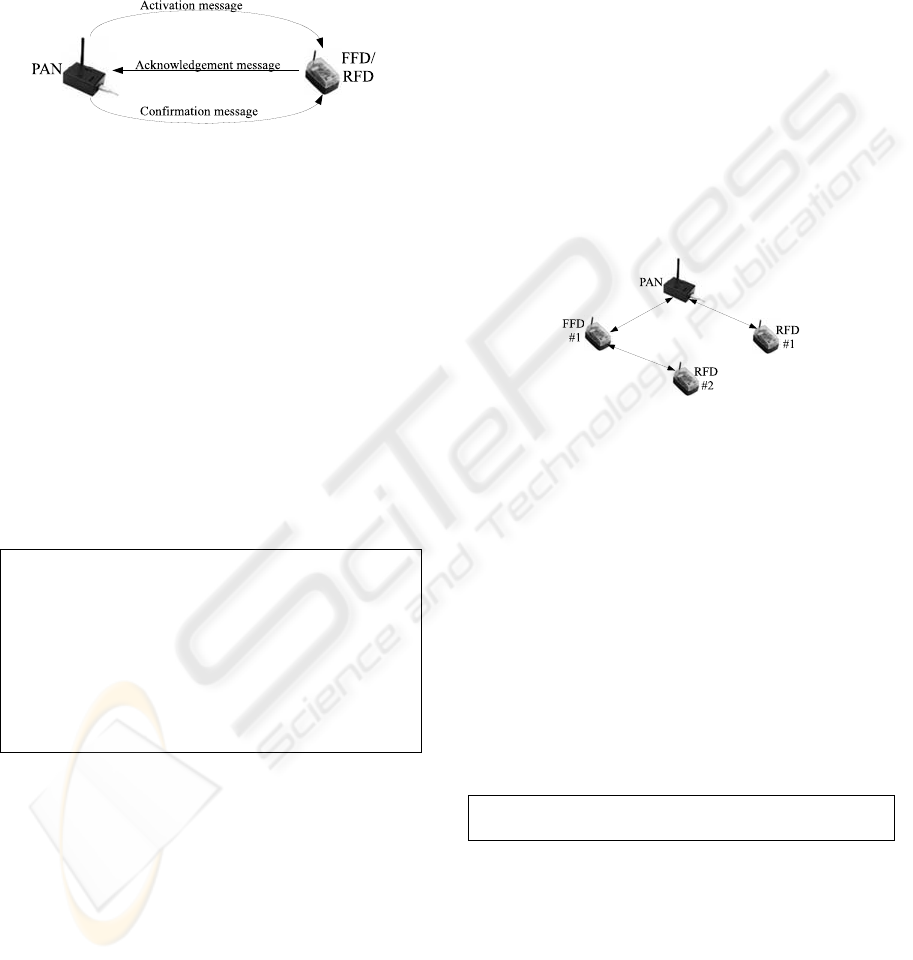
negotiation schema presented in the Figure 3:
Figure 3: Self-destruction activation via negotiation.
After the node’s self-destructing sequence is
started, a set of detrimental actions will be
performed: a)Erase the RAM memory and other
additional memories; b) Drain the node’s battery in
different ways like R/T radio flood or node logical
unit infinite cycle; c) Destroy the node’s radio
device; d)Delete the node’s unique identifier from
the lists of each of the neighboring nodes, including
the base station (disable auto-organization property);
e)Mask the node’s measurement nature by hiding the
type of the sensor that has been used. For every
network node, the self-destruction procedure will be
performed concurrently using threading support for
speed optimization. Node self-destructing sequence
is described by the following pseudocode:
void SELF_DESTRUCTION (sensor A){…
WHILE (sensor A is in network){
START thread {CONSUME battery};
START thread{
ERASE node memory; //erase RAM and flash memory
DISABLE auto-organization property;
DESTROY node_radio_device;
MASK node_measurement_nature; r} }…}
Figure 4: Node self-destruction.
After this procedure is finished, the node will be
untraceable in the network and will not be taken in
consideration for the next “identification” PAN
procedure. When cluster-tree depth “identification”
procedure outputs a single level in the network, the
PAN node will have to self-destruct. Being the
network coordinator and the only alive node with
“sensitive” data, an efficient way to fulfil this
procedure is to erase its memory entities.
3 CASE STUDY
In order to validate our self-destruction
methodology, an experimental wireless sensor
network in a cluster-tree topology was implemented.
The cluster-tree sensor network used in the proposed
application is composed of 4 MicaZ nodes (Figure
5) and a base station – a laptop. Every MicaZ node
is equipped with one ATmega128L microcontroller,
one CC2420 radio device model and three storage
units: one program flash (not writeable), one
measurement flash and one configuration flash. To
assure the communication with the base station
controller, the network PAN uses the MIB520
gateway. All the FFD motes use temperature sensors
for measurements, and all the network nodes are
running under TinyOS. The nesC language assures
TinyOS programming support.
Figure 5: The Crossbow MicaZ network.
We consider that at the initial moment, the
network is functional and the data packets are
beginning to arrive to the base station controller. At
a certain moment in time we intend to interrupt the
network normal workflow and to initialize the self-
destruction procedure. All further actions will be
separated in three major steps as follows:
A) The base station controller will send the self-
destruction activation message to the PAN node.
This could be done using a Java based infrastructure
for communicating with the nodes. Using the
TinyOS external tools (SerialForwarder or Listen
tool), a package will be sent from the PC to a certain
node. The message will have the following structure:
typedef nx_struct ExternalActivationMsg {nx_uint16_t
destNodeid; nx_uint16_t type;} ExternalActivationMsg;
Figure 6: Message_t structure and external message.
B) The coordinator node hosts a TinyOS
application that waits for external messages to
arrive. When the PAN node receives a message of
the type described above, a self-destruction
activation message will be sent over the network:
SELF-DESTRUCTION PROCEDURE FOR CLUSTER-TREE WIRELESS SENSOR NETWORKS
65

event message_t* Receive.receive(message_t* msg,
void* payload, uint8_t len){
if (len == sizeof(ExternalActivationMsg)) {
ExternalActivationMsg* externalMessagePointer =
(ExternalActivationMsg*)payload;
if((externalMessagePointer->destNodeid ==
0)&&(externalMessagePointer->type ==
AM_EXTERNAL))
post sendSDMessage(); …}
Figure 7: PAN node Receive.message event.
In the case of multihop communication, the
message body has to include the destination address
that will be used by intermediary nodes to route the
message toward the specified node. The PAN node
will perform a task to activate the self-destruction
(SD) phase for every node:
SDActivationMsg* activationMessagePointer =
(SDActivationMsg*)(call Packet.getPayload(&myMsg,
NULL));
activationMessagePointer->nodeid = TOS_NODE_ID;
activationMessagePointer->type = AM_DATA2NODE;
if (call AMSend.send(AM_BROADCAST_ADDR,
&myMsg, sizeof(SDActivationMsg)) == SUCCESS) busy
= TRUE;…
Figure 8: SD activation message sending.
C) At node level, when the SD activation
message is received, the node will reply with an
acknowledgement message and will wait for a
confirmation message from PAN. When this
message arrives the node self-destruction is started:
AckMsg* ackMessagePointer = (AckMsg*)(call
Packet.getPayload(&myMsg, NULL));
ackMessagePointer->source = TOS_NODE_ID;
ackMessagePointer->type = AM_DATAACK2BASE;
if (call AMSend.send(BASE_STATION_ADDRESS,
&myMsg, sizeof(AckMsg)) == SUCCESS) busy =
TRUE;
Figure 9: Node acknowledges message reception.
For memory erasing, we used already
implemented interfaces PageEEPROM and
InternalFlash for ATmega128L platform. For
exhausting the node battery, large payload messages
are broadcasted in a repetitive manner. To obtain
large payload messages we changed the value of the
TOSH_DATA_LENGTH TinyOS constant that stores
the default size of the message.
Figure 10: Self-destruction process workflow.
For an easier understanding of the process we
developed the workflow presented in Figure 10,
corresponding to the network topology described in
the Figure 5. Initially, the network is running
normally. At a moment in time, a self-destruction
decision is taken at the base station level and the
base station controller sends an activation message
to the network coordinator. The PAN node will
forward this activation message to every network
node. Further, every node will run its self-
destruction program including the coordinator.
Because we used a cluster-tree topology, the
network’s components will be destroyed using a
bottom-up destruction strategy (starting with farthest
leafs of the cluster-tree and ending with PAN).
4 CONCLUSIONS
This paper introduces the concept of self-destruction
as final phase in the lifecycle of a cluster-tree
wireless sensor network. It brings into attention a
new technique for information security
improvement, adding a self-destruction phase at the
end of the WSN lifecycle. We designed a complete
procedure for network informational destruction that
has benefits for both civil and military networks. We
intend to extend this concept for mesh networks.
REFERENCES
C. Karlof, D. Wagner, 2003. Secure routing in wireless
sensor networks: attacks and countermeasures. Proc.
of the First IEEE International Workshop on Sensor
Network Protocols and Application, pp.113- 127.
D. Curiac, O. Banias, F. Dragan, C.Volosencu, O. Dranga,
2007. Malicious Node Detection in Wireless Sensor
Networks Using an Autoregression Technique. ICNS,
3rd International Conference on Networking and
Services, Athens, pp 83-88.
WINSYS 2009 - International Conference on Wireless Information Networks and Systems
66

M. Dohler, 2008. Wireless sensor networks: the biggest
cross-community design exercise to-date. Bentham
Recent Patents on Computer Science, pp.9- 25.
J. Steffan, L. Fiege, M. Cilia, A.Buchmann, 2005.
Towards Multi-Purpose Wireless Sensor Networks.
Proceedings of Systems Communications, pp 336-341.
S. C. Ergen, 2004. ZigBee/IEEE 802.15.4 Summary.
http://www.eecs.berkeley.edu/csinem/academic/public
ations/zigbee.pdf, pp 1-35.
A. Koubaa, M. Alves,, M. Attia, A. Van Nieuwenhuyse,
2006. Collision-Free Beacon Scheduling Mechanisms
for IEEE 802.15.4/Zigbee Cluster-Tree Wireless
Sensor Networks. Technical Report, Version 1.0,
http://www.open-zb.net/, pp 1-16.
K. Sohrabi, J. Gao, V. Ailawadhi and G. J. Pottie, 2000.
Protocols for Self-Organization of a Wireless Sensor
Network. IEEE Pers. Comm. Mag., v.7, no.5, pp16-27.
Y. C. Wong, J. T. Wang, N. H. Chang, H. H. Liu, C. C.
Tseng, JUNE 2008. Hybrid Address Configuration for
Tree-based Wireless Sensor Networks. IEEE
Communications Letters, VOL. 12, NO. 6, pp 414-416.
SELF-DESTRUCTION PROCEDURE FOR CLUSTER-TREE WIRELESS SENSOR NETWORKS
67
