
SHORT RANGE ULTRASONIC COMMUNICATIONS IN AIR
USING QUADRATURE MODULATION
Chuan Li, David Hutchins and Roger Green
School of Engineering, University of Warwick, Coventry, U.K.
Keywords: Digital communications, Modulation, Ultrasonic signals.
Abstract: A study has been undertaken of ultrasonic communications methods in air, using a quadrature modulation
method. Simulations were first performed in order to establish the likely performance of Quadrature Phase
Shift Keying (QPSK) over the limited bandwidth available in an ultrasonic system. QPSK modulation was
then implemented within an experimental communication system, using capacitive ultrasonic sources and
receivers. The results show that such a system is feasible in principle for communications over distances of
several metres, using frequencies in the 200-400 kHz range. Data rate is typically at 200 kbps.
1 INTRODUCTION
In recent years, short range wireless communications
have been mostly dominated by RF systems, using a
wide variety of technologies, including popular
commercial protocols such as IEEE802, and
Bluetooth amongst others. Here, a short range is
usually defined as 10m to 50m indoors and 50m to
200m outdoors, although propagation over longer
ranges is possible. Other techniques for short range
use include infrared communications (Kueda, 1979),
using protocols such as those of the IrDA (Bloch et
al. 2008). The data rate in such communication
systems can typically be from kbps to Gbps. These
methods are successful and in widespread use.
However, there are other types of signal by which
information can be communicated over short
distances, which may have an advantage in certain
situations. One such consideration is security
(Nakrop et al 2008). For instance, RF signals are
easy to intercept, and various forms of encoding are
needed to maintain secure data transfer (Tsusomu et
al 1990). Infrared technology is, in principle, more
secure for short-range use, but it is also generally
more directional, and does not pass through most
barriers such as walls and partitions.
An alternative approach is to consider the use of
ultrasound in air for communications. This offers
several advantages over existing methods, especially
for security – it is effectively blocked by most
barriers, and has a limited propagation range, making
interception from outside a room very difficult. It
also has other qualities. For instance, the slow
propagation speed in air allows the location of
sources to be tracked. In addition, problems due to
multi-path effects (interference from direct and
reflected signals) can potentially be reduced, because
of the difference in propagation time for multiple
paths. Despite these attractive qualities, development
of ultrasonic short-range communication systems has
been somewhat restricted, due to the narrow
bandwidth of available acoustic transducers and the
high attenuation of ultrasound signals in air at
frequencies above 2 MHz. However, with recent
developments in transducer technology for use in air,
including wide bandwidth capacitive designs used in
this work (Li et al, 2008), the effective operating
bandwidth now stretches to 1 MHz and beyond. As a
result, reasonable data rates of up to several hundred
kbps can be expected, provided suitable modulation
data recovery methods are developed.
In this paper, we describe the use of Quadrature
Phase Shift Keying (QPSK) in an ultrasonic
communications system for use in air. The properties
and characteristics of this approach have been
measured and simulated, as will now be described.
2 RAISED COSINE FILTER
One of the best filter forms to minimise the effect of
Inter Symbol Interference (ISI) as well as reducing
the frequency range of the transmitted signal is to
100
Li C., Hutchins D. and Green R. (2009).
SHORT RANGE ULTRASONIC COMMUNICATIONS IN AIR USING QUADRATURE MODULATION.
In Proceedings of the International Conference on Wireless Information Networks and Systems, pages 100-104
DOI: 10.5220/0002224601000104
Copyright
c
SciTePress
apply Raised Cosine (RC) filtering to baseband
binary stream. The effective bandwidth of such filter
is determined by the roll of factor α, and can be
related to the symbol rate R
s
by the following
expression
α
+
=⋅=
1
log
2
B
LRR
bs
(1)
where R
b
is the bit rate of the baseband signal in bps,
L is the modulation level (L=4 for QPSK), and B is
the absolute filter bandwidth in Hz.
3 EXPERIMENT
The experiments used a capacitive transducer to
transmit and receive ultrasonic signals in air. These
devices, which have been described in a previous
publication (Li et al, 2008), were constructed with a
micromachined silicon backplate and a 3-5 μm thick
Mylar membrane. For such a transducer, the
bandwidth of the signal is dependent on the applied
dc bias voltage, film thickness, and the nature of the
transient voltage used for excitation. Ultrasound is
generated by applying a transient voltage V(t),
generating a field between the front surface of the
membrane and the conducting backplate. The
efficiency and bandwidth are both increased by
superimposing a dc bias field upon the transient
voltage. As a receiver, the detected sound wave at the
membrane varies the capacitance, and in the
presence of the dc bias, a dynamic charge is
generated on the electrodes.
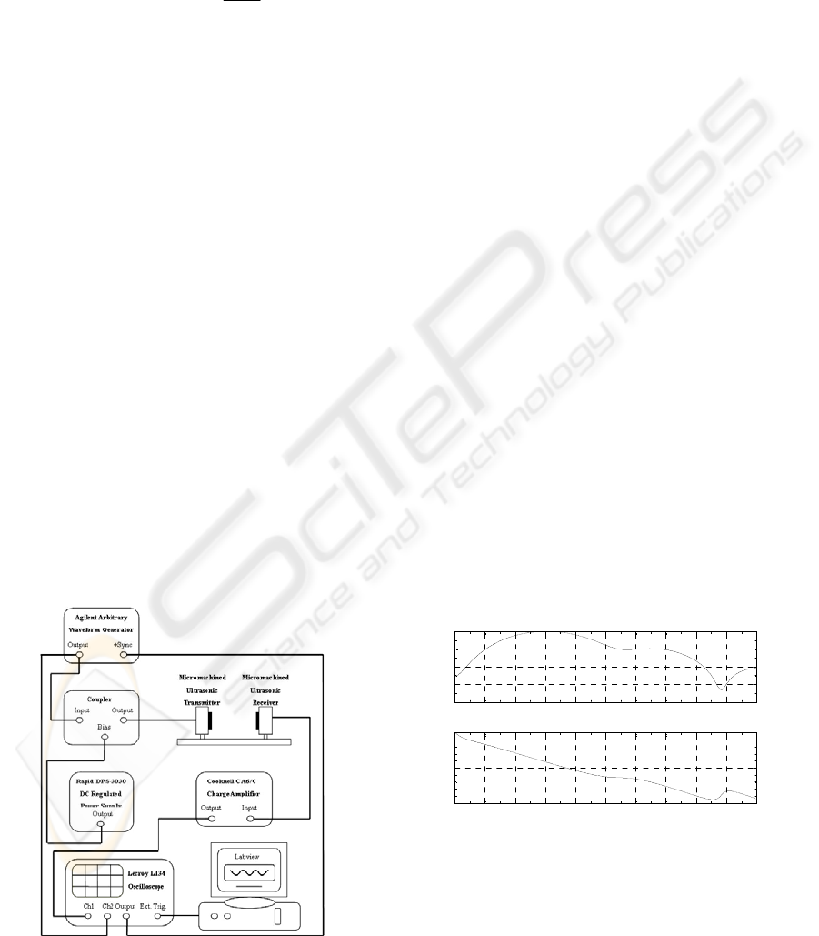
Figure 1: Schematic diagram of the apparatus used to
transmit ultrasonic communications signals in air.
Figure 1 shows a typical experimental
arrangement, where the transmitter and receiver are
placed at a distance of 1.2 metres apart. The
transmitter has a membrane thickness of 5 um, so as
to withstand higher excitation voltages without
causing damage to the polymer membrane. The
source was driven by an Agilent 33120A Arbitrary
Waveform Generator, with a superimposed +100 V
dc bias voltage generated by a dc power supply. This
supplied the required digital signal for transmission.
A linear power amplifier with a gain of 25 dB was
used to boost the output of the waveform generator
before application to the transmitting transducer. The
receiver had a film thickness of 2.5 um and was
followed by a Cooknell CA6/C charge amplifier with
a gain of 250 mV/pC. The response was then fed into
a LeCroy LT342 digital oscilloscope for signal
analysis. Finally, the waveforms were saved on a PC
running LabVIEW programs for offline signal
processing. A physical synchronisation link was
established between the waveform generator and the
oscilloscope. This removed the need for wireless
handshaking, which would be needed in a real
application.
Note that the signal amplitude from the linear
power amplifier applied to the transmitting
transducer was typically set at 200V peak-to-peak,
and the received signal amplitude was typically
around 5 mV RMS at 1.2 metres range. The
experiment was performed in an indoor laboratory,
where room temperature was about 25 °C, and where
the relative humidity was around 79%. The recorded
background noise level was around 600 μV RMS,
with negligible air turbulence to influence the signal
transmission.
0 100 200 300 400 500 600 700 800 900 1000
-40
-30
-20
-10
0
Frequency (kHz)
Magnitude (dB)
(a)
0 100 200 300 400 500 600 700 800 900 1000
-10
-5
0
Frequency (kHz)
Magnitude (dB)
(b)
Figure 2: (a) magnitude and (b) phase response of the
ultrasonic system as measured experimentally.
The measured overall response of the
communication channel (in terms of amplitude and
phase) was required, for the simulations of the
quadrature approach which appear in the next
SHORT RANGE ULTRASONIC COMMUNICATIONS IN AIR USING QUADRATURE MODULATION
101
Section of this paper. As shown in Figure 2(a), the
magnitude response peaks at 300 kHz, but has a dip
at 880 kHz. The 6 dB bandwidth of the measured
channel is about 350 kHz, and the usable frequency
range is about 900 kHz. Figure 2(b) shows that the
phase response of the channel is roughly linear
across the 6 dB bandwidth.
4 RESULTS AND DISCUSSION
As can be seen in Figure 3, a pulse-shaped QPSK
signal outperforms an unfiltered QPSK signal at the
receiver in terms of BER at the same level of E
b
/N
o
,
as the improvement in bandwidth efficiency
achieved by shaping reduces the noise bandwidth
relative to the unshaped signal bandwidth. The above
data was obtained by simulating the channel
response with Additive White Gaussian Noise
(AWGN).The E
b
/N
o
level was incremented in 0.5 dB
steps from 8- 22 dB. Even with a roll-off factor as
small as 0.2, at a bit rate of 200 kbps, the overall
bandwidth of the modulated carrier was reduced
from 200 kHz to 120 kHz (referenece to Eqn.1), at
the same time producing a lower BER. Note that, as
the level of E
b
/N
o
increased, the benefits of using
shaped pulses instead of unshaped pulses were
enhanced further.
8 10 12 14 16 18 20 22
10
-4
10
-3
10
-2
10
-1
10
0
BER vs. Eb/No Simulation with Best Curve Fit
Eb/No (dB)
BER
α = 0.2
α = 0.2 Best Curve Fit
α = 0.5
α = 0.5 Best Curve Fit
α = 0.8
α = 0.8 Best Curve Fit
Unshaped
Unshaped Best Curve Fit
Figure 3: Simulation of performance with and without
pulse shaping.
The above simulations indicated that ultrasonic
communications based on QPSK signals would be
feasible across a distance in excess of 1 m in air.
Experiments were thus performed to confirm that
this was the case, and to indicate how the
performance was modified by changes in factors
such as the roll-off factor (α) of the RC filter used
with QPSK modulation.
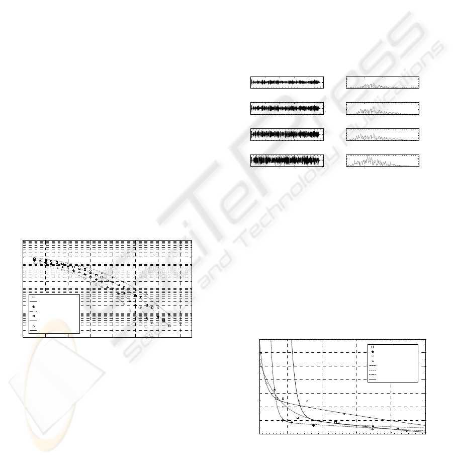
Figure 4 shows the results of an experiment in air,
using two capacitive transducers in the arrangement
shown earlier in Figure 1. The distance between the
transducers was 1.2 m, and the bandwidth used was
120 – 200 kHz, depending on the roll off factors α
(reference to Eqn.1). Bit rate was chosen to be 200
kbps, and the frequency of carrier is 300 kHz. The
figure shows the received ultrasonic waveform for
four values of α on the left, with the equivalent
frequency spectrum on the right in each case. It can
be seen that the amplitude of the received QPSK
waveform increased with an increase of the pulse
shaping roll-off factor. The received unshaped QPSK
signal tended to give the strongest signal of the four
cases; however, it occupied the widest bandwidth,
and this is a disadvantage when bandwidths are
limited in an ultrasonic communication system.
0 0.2 0.4 0.6 0.8 1
-10
0
10
A (mV)
200 250 300 350 400
0
5
FFT
(a)
0 0.2 0.4 0.6 0.8 1
-10
0
10
A (mV)
200 250 300 350 400
0
5
FFT
(b)
0 0.2 0.4 0.6 0.8 1
-10
0
10
A (mV)
200 250 300 350 400
0
5
FFT
(c)
0 0.2 0.4 0.6 0.8 1
-10
0
10
Time (ms)
A (mV)
200 250 300 350 400
0
5
Frequency (kHz)
FFT
(d)
Figure 4: Results of a QPSK ultrasonic transmission across
air for values of α of (a) 0.2, (b) 0.5, (c) 0.8 and (d) an
unshaped experiment (α = 1), at distance of 1.2 m. Time
waveforms are on the left, frequency spectra on the right.
It is also clear that in all four spectra, transmitted
signals have been ‘filtered’ by the channel magnitude
response, which includes the response of the
frequency selective attenuation in air whilst
propagating over a relatively long range, such that
the higher frequencies are attenuated more than the
lower frequencies.
20 25 30 35 4
0
0.15
0.2
0.25
0.3
0.35
0.4
0.45
0.5
Eb/No (dB)
EVM
α = 0.5
α = 0.8
Unshaped
α = 0.2
α = 0.5 Best Curve Fit
α = 0.8 Best Curve Fit
α = 0.2 Best Curve Fit
Unshaped Best Curve Fit
Figure 5: Experimental EVM and Eb/No that results from
the transmitted QPSK signal at 1.2 metres, for various
values of α.
Using the transmitted QPSK as a reference, the
WINSYS 2009 - International Conference on Wireless Information Networks and Systems
102
experimental performance in terms of EVM can be
evaluated. Discrete experimental results are
presented, together with a best fitting curve to the
data in Figure 5, for various values of α. Note It has
been found in this experiment that an EVM value
higher than 0.2 will lead to a severe BER in
decoding, which could cause the transmitted
information to become unusable. thus, whilst the
unshaped response may appear attractive in terms of
amplitude, there are other factors to be considered in
a real communication system.
Figure 5 shows that at high Eb/No (over 35dB),
unshaped QPSK appears to achieve a lower value of
EVM, and hence a better performance. However, at
low Eb/No values (less than 22 dB), a shaped QPSK
becomes of more value. With α = 0.8, a reliable
communication link could be established when
Eb/No is greater than 20dB. On the other hand, if
bandwidth efficiency is the top priority, by setting α
= 0.2, the channel will not be sufficiently robust
unless the Eb/No ratio reaches a value of 35 dB.
However, with α = 0.5, a reasonable compromise
between bandwidth occupation and performance can
be expected, within the range 19dB - 33 dB.
-1.5 -1 -0.5 0 0.5 1 1.5
-1.5
-1
-0.5
0
0.5
1
1.5
Quadrature
In-P hase
Constellation Diagram
-1.5 -1 -0.5 0 0.5 1 1.5
-1.5
-1
-0.5
0
0.5
1
1.5
Quadrature
In-Pha se
Constellation Diagram
(a) (b)
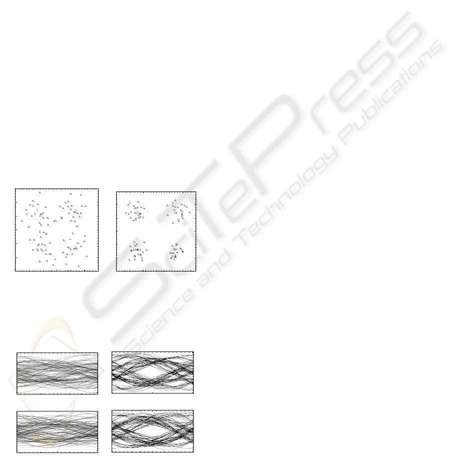
Figure 6: Constellation diagram for received QPSK with (a)
α = 0.2 and (b) α = 0.8. The crosses represent the
amplitude of each channel after decoding.
-5 0 5
-2
-1
0
1
2
Time (
μ
s)
Amplitude (mV)
Eye Diagram for In-Phase Signal
-5 0 5
-2
-1
0
1
2
Time (
μ
s)
Amplitude (mV)
Eye Diagram for Quadrature Signal
-5 0
5
-2
-1
0
1
2
Time (
μ
s)
Amplitude (mV)
Eye Diagram for In-Phase Signal
-5 0
5
-2
-1
0
1
2
Time (
μ
s)
Amplitude (mV)
Eye Diagram for Quadrature Signal
(a) (b)
Figure 7: Eye diagram for (a) 0.2 and (b) 0.8 roll off.
Figure 6-7 show the constellation and eye
diagrams for QPSK with α = 0.2 and α = 0.8. It can
be seen that the linear phase response of the system
has kept the QPSK constellation in place regardless
of the unbalance of magnitude response. This again
emphasises the advantages of using phase
modulation. The more open the eye, the better the
separation in the scatter plot, which also means that
the SNR is better. Hence, signal transmission is
likely to be more robust (less susceptible to noise).
The horizontal width of the eye diagram (Figure 7)
represents the time over which the signal can be
successfully treated to decode the signal – i.e. the
wider the eye the better. From Figures 6 to 7, it is
evident that a wider eye has resulted from an
increase in the value of α.
5 CONCLUSIONS
Initial simulations indicated that QPSK modulation
would be a good choice for ultrasonic
communications in air. Experiments identified the
frequency response of the airborne ultrasonic system
in terms of amplitude and phase. This was then used
to design the approximate characteristics that would
be needed in a QPSK system for ultrasonic use with
the transducers used. Reasonable performance in
terms of BER and E
b
/N
o
was obtained in both
simulations and subsequent experiments. The results
have indicated that a QPSK approach can be used to
propagate ultrasonic signals in air over reasonable
distances in the 1-2 m range indoors.
The choice of filter seems to have a relatively
large effect on performance. This is characterised by
the value of α. In most conventional RF
communication systems, α tends to be set at a value
of around 0.2, and indeed a value of α = 0.2 is
recommended for ultrasonic use. The above work
was performed over relatively short distances in a
laboratory environment. In practice, other factors are
likely to influence performance (e.g. turbulence,
frequency-dependent attenuation in air, multi-path
problems etc). All these factors are currently under
investigation.
REFERENCE
Keda Y., K., Yoshihiro, O. and Hiroshi, U. (1997)
“International standard of infrared data communication,
SHORT RANGE ULTRASONIC COMMUNICATIONS IN AIR USING QUADRATURE MODULATION
103

IrDA”, Shapu Giho/Sharp Technical Journal, n 68, pp.
11-17
Bloch M., Barros J., Rodrigues Miguel R.D., and
McLaughlin SW. (2008), “Wireless
Information-theoretic Security”, IEEE Transactions on
Information Theory, v 54, n 6, pp. 2515-2534.
Nakrop, J., Sodsai, W., Prasit N. and Atipong, S. (2008),
“Security System against Asset Theft by Using Radio
Frequency Identification Technology”, 5th
International Conference on Electrical
Engineering/Electronics, Computer,
Telecommunications and Information Technology,
2008, pp. 761-764
Tsutomu, T., Masahiro, S. and Susumu, Y. (1990),
“Multipath delay estimation for indoor wireless
communication”, Proc. IEEE Vehicular Technology
Conference, pp. 401-406.
Li C., Hutchins D.A. and Green R.J. (2008), “Short-range
ultrasonic digital communications in air”, IEEE Trans.
Ultras. Ferr. Freq. Contr. v. 55, pp. 908-918.
WINSYS 2009 - International Conference on Wireless Information Networks and Systems
104
