
IDENTIFICATION OF SOFTWARE SYSTEM COMPONENTS USING
SEMANTIC MODELS AND GRAPH SLICING
Mark McKenna, Jacob Slonim, Michael McAllister
Faculty of Computer Science, Dalhousie University
6050 University Avenue, Halifax, Nova Scotia, Canada
Kelly Lyons
Faculty of Information, University of Toronto, 45 Willcocks Street, Toronto, Ontario, Canada
Keywords:
Software decomposition, Legacy software, Relationship modeling framework, Components, Semantic model,
Abstraction, Graph slicing, Program slicing, Dependency detection.
Abstract:
We present an implementation of part of a process for automatically decomposing a legacy software system
into a loosely coupled components. The Relationship Modelling Framework (RMF) coupled with the appro-
priate components can generate and maintain a semantic model of a software system that shows at various
levels of abstraction the elements that make up a software system such as source code entities, database tables,
and the relationships between these elements. We introduce graph slicing, derived from program slicing, that
can assist architects by identifying dependencies of selected elements. IBM provided independent preliminary
validation of the model generation process’ performance and the accuracy of the graph slicing by applying the
results to one of their real-world software suites.
1 INTRODUCTION
Software systems evolve over time (Lehman, 1996).
Systems grow and often become more complex in re-
sponse to changing needs and expectations motivate
the growth. The increases in complexity motivate
refactoring and reengineering to simplify the system
and facilitate future change.
The structure of a software system “...comprise[s]
software elements, the externally visible proper-
ties of those elements, and the relationships among
them.” (Bass et al., 2003). The structure of a software
system is not always obvious to the engineers of the
system, yet knowing this structure can be invaluable
when reengineering. Aspects of a system’s structure
can be spread across multiple documents or be visible
in some documents, like high level design documents,
and not in others, such as source or object code. Of-
ten, aspects of the structure of a software system are
only visible when several different kinds of document
are considered together. For example, source code
documents, library files, and a database catalog may
all be required to understand how a software system
interacts with a database repository. Implicit structure
is more difficult to understand and maintain.
In this paper, we hypothesize that a semantic
model of a software system comprised of many dif-
ferent kinds of documents can be extracted from an
existing system and that such a model can be automat-
ically processed to provide insight into the structure of
the modelled system for the purpose of software de-
composition. We introduce the idea of graph slicing,
an analogue of program slicing on more general se-
mantic graphs, to allow for ‘slicing’ of entire software
systems. Slicing the entire system provides insight
into extracting and isolating services that already exist
in such a system, whether for refactoring or for rede-
ployment in a Service Oriented Architecture (Object
Management Group, 2006). We develop the Relation-
ship Modelling Framework (RMF) to assist users in
generating and maintaining semantic models of soft-
ware systems based on the documents that describe
the system.
Our preliminary validation provides evidence that
a semantic model can provide insight into the struc-
ture of existing systems. We use a prototype of RMF
and graph slicing to generate a semantic model of a
large legacy software system based on the J2EE spec-
ification and to extract a complete dependency tree for
a chosen component of the software system.
5
Mckenna M., Slonim J., McAllister M. and Lyons K. (2009).
IDENTIFICATION OF SOFTWARE SYSTEM COMPONENTS USING SEMANTIC MODELS AND GRAPH SLICING.
In Proceedings of the 4th International Conference on Software and Data Technologies, pages 5-12
DOI: 10.5220/0002219700050012
Copyright
c
SciTePress

The contributions of this work are the Relation-
ship Modelling Framework, the graph slicing concept,
and the application of these to the identification of
software system components for the purposes of soft-
ware decomposition.
We describe the relevant background literature in
Section 2 and the software decomposition process
used in our solution in Section 3. The core results on
graph slicing and the RMF architecture appear in Sec-
tion 4 followed by our validation in Section 5 and the
results of the validation in Section 6. We summarize
the paper and provide future directions in Section 7.
2 BACKGROUND
This section describes other tools and techniques that
exist for supporting the reengineering of software sys-
tems. We also describe semantic modelling as the
base structure of our software system.
2.1 Software Reengineering
Software reverse engineering is the process of deriv-
ing elements of a software system’s design through
analysis of its structure and behaviour. Software
reengineering is a process of iteratively reverse en-
gineering and forward engineering through which the
structure and behaviour of an existing software sys-
tem is modified. One specific type of software reengi-
neering is software decomposition.
2.1.1 Software Decomposition
Software decomposition is an important element of
software reengineering (Lung et al., 2005a; Lung
et al., 2005b; Marciniak, 1994). Schmitt defines it as
“The process of breaking the description of a system
down into small components. . . ”(Schmitt, 2007). The
goal of software decomposition is to produce com-
ponents that maximize intra-component cohesion and
minimize inter-component coupling.
A first step in software decomposition is in un-
derstanding the existing program structure. For ex-
ample, Mitchell and Mancoridis (Mitchell and Man-
coridis, 2002) provide tools to extract abstractions
from source code. Marin et al. (Ceccato et al., 2006)
provide techniques for aspect and concern mining to
identify cross-cutting items in a source base. These
techniques can be used within the extraction layer of
our RMF architecture (Section 4.1) to provide new re-
lations between code artifacts.
One of the primary challenges when decomposing
an existing software system is determining the bound-
aries for the decomposition that achieve the best cohe-
sion and coupling characteristics. A number of tech-
niques (Bauer and Trifu, 2004; Lung et al., 2005a;
Weiser, 1981) have been described to help in decom-
position. In our research, we deal with one particular
technique called program slicing.
Program slicing, introduced by Weiser (Weiser,
1981), is a technique that produces a minimal sub-
set of a program that implements a selected portion
of that program’s behaviour, called a program slice.
Program slices are often derived by starting from a
selection of variables, program statements, and other
functional components of a program and tracing their
areas of effect. The most common slices retain the
portion of the code that affects the value of a set of
variables, or the outcome of the execution of a set of
program statements. In procedural languages, such
slices can be computed using the control- and data-
flow dependency information about the program.
Variations on program slicing have been described
for more granular program structures such as code
modules (Beck and Eichmann, 1993), and in an in-
teractive editor-supported fashion (Ning et al., 1993).
Program slicing has been applied to software develop-
ment problems that include testing, reuse, knowledge
discovery, maintenance and evaluation.
2.1.2 Reengineering Tools
Several tools and techniques exist to help in the soft-
ware reengineering process. Unravel (Lyle and Wal-
lace, 2007) is a prototypical program slicing project,
designed to implement program slicing on the ANSI
C programming language.
Rigi (M
¨
uller et al., 1992) uses a graph-based rep-
resentation of the code components of a software sys-
tem to facilitate “semi-automatic” reverse engineer-
ing of the system. It automatically builds a low-level
model of the system code, then allows the system
analyst to construct logical views over the low-level
model, creating a semantic model of the system at a
somewhat higher level of abstraction. Rigi focuses on
modelling system structure evident from the source
and/or compiled code objects of the system, produc-
ing abstractions as an interactive process.
CodeSurfer (G. Balakrishnan and R. Gruian and
T. Reps and T. Teitelbaum, 2005) is a software system
that enables the browsing of system source code at a
low level. It “. . . understands pointers, indirect func-
tion calls, and whole-program effects.” (GrammaT-
ech, Inc., 2007) CodeSurfer implements many funda-
mental analyses of source code, including call graphs
and control- and data-flow analyses. An integrated vi-
sualization tool presents several pre-defined views of
the system model.
ICSOFT 2009 - 4th International Conference on Software and Data Technologies
6

The Software Bookshelf modelling system by
Finnigan et al˙ (Finnigan et al., 1997) acts as a central
repository for documentation for a legacy system. It
specifies four levels of abstraction for documentation
artifacts and groups the artifacts according to source
types. While the Software Bookshelf provides simi-
lar functionality to the RMF architecture of this paper,
the Software Bookshelf has an emphasis on access to
a human patron while our RMF work aims more at
access for machine processing.
Egyed and Medvidovic (Egyed and Medvidovic,
2000) augment general-purpose modelling techniques
such as UML with special-purpose modelling tech-
niques that model and analyse specific interactions.
Their research focuses on maintaining consistency
and enabling conversion between models to retain the
advantages of each model.
2.2 Semantic Modelling
A semantic model (Salter, 2001) abstractly represents
the structure or behaviour of a system. It is a gen-
eral model that can represent a variety of concepts
and the relationships between those concepts concur-
rently or independently. One important capability
of a semantic model is the representation of meta-
information along with the information it describes.
The meta-information allows users of the model to
reason about the information, deriving new informa-
tion from it. Meta-information becomes especially
useful when tracing the lineage of semantic model
components that are automatically created.
One place where semantic models are used exten-
sively is in the Semantic Web. The Semantic Web is
an extension of the World Wide Web that exposes web
content in machine-readable form, in addition to nat-
ural language form. The Semantic Web is the notion
of a world-wide hyper-linked network in which the
data are individual concepts and the hyperlinks rep-
resent the relationships between those concepts. This
is in contrast to the ‘legacy’ or existing World Wide
Web in which the data are documents and the hyper-
links represent functional associations between those
documents.
The Resource Description Framework
(RDF) (Group, 2007) is a language, specified
by the World Wide Web Consortium (W3C), for
representing a semantic model as a directed, vertex-
and edge-labelled multigraph. This representation
enables the application of many existing graph
algorithms and techniques to the semantic model. We
use this conceptually simple model to represent our
semantic graphs, although other representations can
be equally effective.
1. Identify a set of desired services, called the primary ser-
vices of the target system.
2. Create a model of the system’s elements and the inter-
dependencies between those elements.
3. For each primary service:
(a) Identify the system elements required to enable the
functionality of that service.
(b) Compute the ‘support set’ of the system elements:
all system elements on which the identified system
elements directly or transitively depend.
4. Intersect the support sets for each primary service to
identify shared functionality between primary services.
5. Partition the model to maximize intra-service cohesion,
and minimize inter-service coupling. This may involve
the creation of secondary services that support the pri-
mary services.
6. Implement the identified services using the code identi-
fied in the legacy system.
Figure 1: Process for result-driven decomposition of a
legacy system. User intervention is required in all steps.
RMF and graph slicing provide automated assistance in
steps 2 and 3.
3 SOFTWARE DECOMPOSITION
PROCESS
We aim to develop automated techniques to help in,
and ultimately perform, a portion of the software de-
composition process. In this section, we outline the
broader context in which the software decomposi-
tion will occur and identify the steps where RMF and
graph slicing can help in the process.
We refer to the software system being decom-
posed as the ‘legacy system’, and the system pro-
duced through decomposition as the ‘target system’.
IBM, our industry partner, is interested in decom-
posing large and complex systems into loosely cou-
pled structures for system reengineering. IBM per-
sonnel regularly participated in this research to pro-
vide insight into the nature of the problem. IBM also
provided arms-length validation of the technology de-
veloped in this research on some of their production
software to ensure that our approach is practical.
Our first step is to identify a general process for
decomposing a legacy software system into a set of
services that we would want to isolate, such as in a
SOA system. This result-driven process is described
in Figure 1. This process is suitable in cases where a
set of desired services is already known or is defined
by the requirements of the system.
All the steps in this process require user inter-
IDENTIFICATION OF SOFTWARE SYSTEM COMPONENTS USING SEMANTIC MODELS AND GRAPH SLICING
7

vention at present. Our work provides automated
assistance for steps 2 and 3. One can envision fu-
ture reengineering research to provide additional as-
sistance and even automation for many of these steps.
We assume that the identification of the set of de-
sired services of step 1 is completed by the analysts of
the legacy system, using other methods. In step 2, an
individual will use our RMF, defined in Section 4.1,
to create a model of the software system. In step 3,
the individual can use graph slicing, defined in Sec-
tion 4.2, to help identify the elements of the legacy
system that expose the functionality desired by each
service. The individual would then also perform a de-
pendency analysis on those elements to identify the
portion of the legacy system that implements the func-
tionality, called the ‘support set’ of that functionality.
We do not directly address the problems of inter-
secting support sets or partitioning the system model
of steps 4 and 5. For intersecting support sets, an
all-pairs intersection approach could be used in small
legacy systems, or one can use a marking scheme in
the semantic graph is the semantic graph and the tran-
sitive closure aspect of graph slicing is used to iden-
tify the support set. Partitioning the system model and
performing the actual reengineering automatically lie
outside the scope of this paper.
4 RELATIONSHIP MODELLING
Creating a model of a legacy system and using that
model to decompose the system requires a represen-
tation for the model, a means to construct the model,
and a means to explore the model.
We use a semantic graph as our representation for
the model. A semantic graph is any directed multi-
graph that represents elements of a software system,
and relationships between those elements. The nodes
of the graph can represent concrete or abstract ele-
ments of the system. The types of the elements can
be heterogeneous as long as relationships between
nodes, the graph edges, are well-defined. Each edge
is also provided a label to indicate the type of rela-
tionship that generated the edge.
For convenience, we encode the semantic graphs
in the RDF language.
By using a graph to represent information about
a software system, there is the possibility that we are
limiting the types of queries that we can perform for
system decomposition. However, the graph represen-
tation and the flexibility in the relationships that de-
fine edges currently allow for dependency analyses
and have nonetheless provided insight into legacy sys-
tems.
We elaborate on the Relationship Modelling
Framework (RMF) to create the semantic graph and
on graph slicing to explore the model in the graph in
the next subsections.
4.1 The Relationship Modelling
Framework (RMF)
RMF is a semantic graph generation, maintenance,
and querying framework. Analysts interact with RMF
to guide the creation and querying of the semantic
graph. Within the framework, an analyst directs RMF
to sources of electronic documents of a legacy system
and directs RMF to mine specific relations and con-
crete and abstract entities from the data sources for
inclusion into a common semantic graph. Through
separate construction steps, the analyst can create a
semantic graph that encodes a diverse collection of re-
lations across a heterogeneous set of source data such
as source code, object code, configuration files, and
scripts. The analyst can then manipulate and query
the semantic graph to identify elements to decom-
pose. The key attribute of RMF is its flexibility in
creating and managing the semantic graph.
RMF consists of three layers, the extraction, gen-
eration and query layers. The extraction layer parses
and processes documents describing the legacy soft-
ware system to extract information about the system.
At a coarse level, the extraction layer contains an ex-
tensible set of strategies for data extraction, where
each strategy is characterized by the type of input
that it can process and the type of data and meta-
information that it can extract from that source. For
example, one strategy could extract data on parent
classes to determine inheritance from a set of Java
class files, a second strategy could extract method call
graphs from C code, and a third strategy could ex-
tract key strings in Enterprise Java Beans (EJBs) that
the generation layer can then link to the databases
tables with which the EJBs interact from both the
EJB source code and XML configuration files for the
EJBs. Each of the strategies for RMF is implemented
in a conventional programming language and is dy-
namically linked and unlinked with an RMF imple-
mentation.
The generation layer uses the information from
the extraction layer to construct or update the seman-
tic graph. The layer specifies the representation of the
semantic graph, manages the addition and possibly re-
moval or contraction of vertices and relations in the
graph, and provides persistence of both the semantic
graph, of meta-information, and of system properties
across different invocations of the RMF framework.
The layer constructs relations between graph entities
ICSOFT 2009 - 4th International Conference on Software and Data Technologies
8
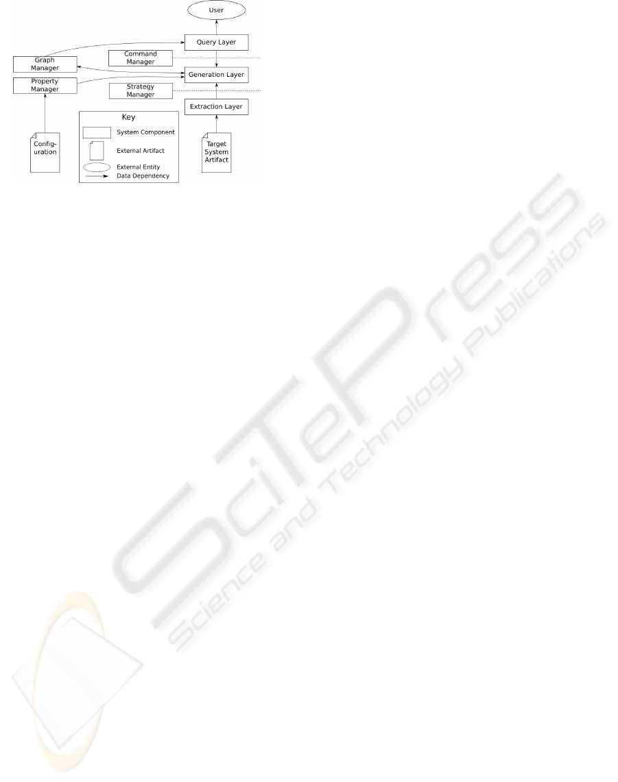
Figure 2: RMF architectural diagram.
based on the data and meta-information from the ex-
traction layer.
The query layer provides an interface to the
user and performs post-processing on the semantic
graph. The query layer provides a command interface
through which the user can invoke modules, which are
sequences of strategies and operations on the seman-
tic graph from the generation layer. Some modules
directly or indirectly trigger the extraction of new el-
ements and relations from data sources while other
modules can execute graph algorithms on the seman-
tic graph such as graph reachability, edge or vertex
contraction, or cut-edge or cut-vertex detection. One
such query is the graph slicing operation described
in section 4.2. As with strategies from the extrac-
tion layer, modules are implemented in a conventional
programming language and are dynamically linked
and unlinked with an RMF implementation.
RMF remains interactive with the analyst at
present to help select the most appropriate relations
for extraction into the semantic graph from the diverse
electronic documents. Automatically including all re-
lations could overwhelm the analyst with excessive
relations in the semantic graph that do not relate to
the sought-after abstraction.
The architecture of RMF is shown at a high level
of abstraction in Figure 2. The diagram shows four
management objects: the graph manager, property
manager, command manager and strategy manager.
The graph manager manages the semantic graph pro-
duced by the framework. The property manager man-
ages persistent configuration information used by the
framework and its component modules. The com-
mand and strategy managers control access to com-
ponents in the generation and extraction layers, re-
spectively. One more management object, the mod-
ule manager, is not shown in this diagram. The mod-
ule manager loads, unloads and manages dependen-
cies for the modules that populate the extraction and
generation layers.
4.2 Graph Slicing
A graph slice of a directed graph G, with respect to a
set S ⊆ V (G), is the subgraph of G that is reachable
from any of the starting vertices of S. The meaning
of this reachability depends on the relations encoded
in the edges of the graph. In a semantic graph where
edges indicate an invocation of one function by an-
other, a graph slice defines the call graph. In a differ-
ent semantic graph where edges indicate class inheri-
tance, a graph slice defines an inheritance tree.
One can view graph slicing as a generalization of
program slicing as applied to a more abstract struc-
ture, namely the semantic graph.
Graph slicing can model other forms of slicing, in-
cluding program slicing. For example, given a graph
G whose vertices represent statements and variables
in a procedural program, and whose edges represent
control- and data-flow dependencies, a graph slice of
G with respect to a vertex set S is equivalent to a pro-
gram slice isolating the statements and variables rep-
resented by the vertices in S (based on the example
program slice given in 2.1.1).
In general, if the vertices of a graph G repre-
sent functional elements of a software system, and
the edges represent functional dependencies between
those elements, then a slice of G with respect to a
set of vertices V represents a component of the soft-
ware system that implements all of the functionality
exposed by the vertices in V . The identified func-
tional elements can then be extracted from the soft-
ware system and used to implement that functionality
independently from the rest of the system.
5 PROTOTYPE
AND VALIDATION
To validate our work, we prototyped an RMF im-
plementation to perform graph slicing on a seman-
tic graph of a large production-quality system. This
prototype differs in one chief way from the system
described in Section 4.1: it does not implement per-
sistence of the semantic graph. This limitation affects
the execution time of the prototype to answer a query
since it must first construct the semantic graph, but it
does not restrict the results of the query.
The analysed software system was a large com-
mercial suite based on Java’s J2EE system (Sun Mi-
crosystems, 2007), designed and developed by IBM.
The company has requested that the software suite re-
main anonymous.
The software suite consists of approximately 5
million lines of code, written exclusively in the Java
IDENTIFICATION OF SOFTWARE SYSTEM COMPONENTS USING SEMANTIC MODELS AND GRAPH SLICING
9
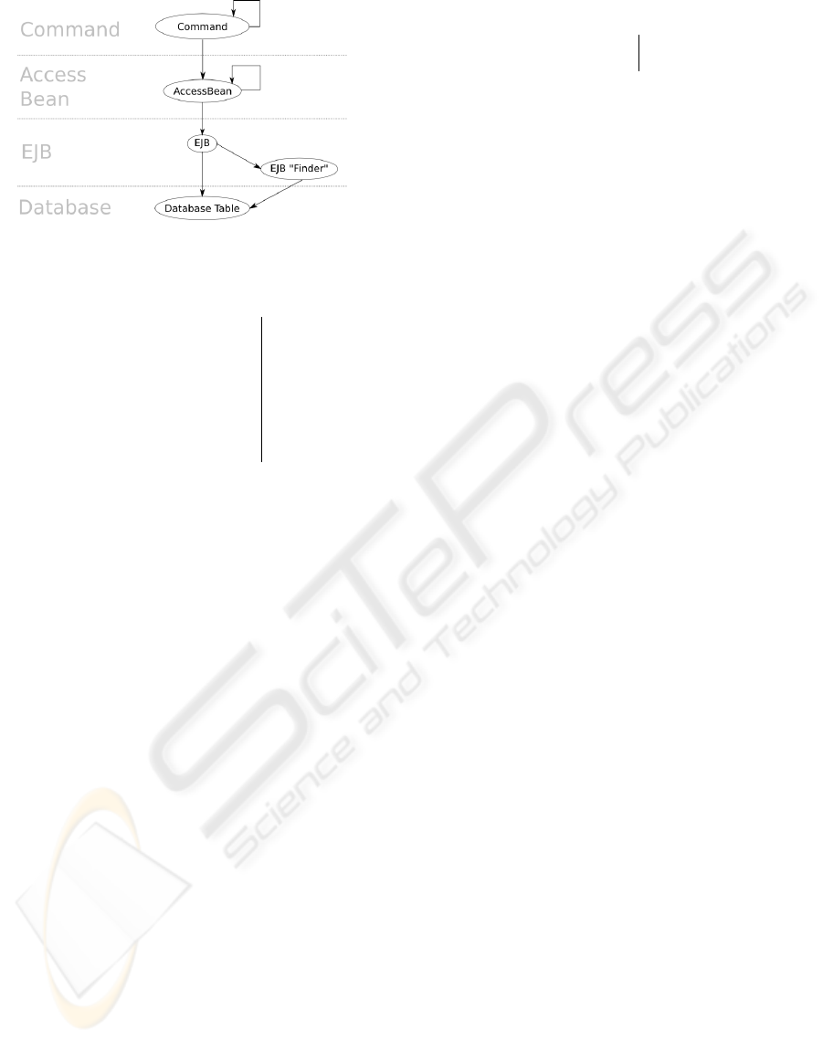
Figure 3: Pattern of dependencies in the J2EE suite.
Table 1: Statistics regarding the J2EE suite.
Lines of code ≈ 5,000,000
Java classes ≈ 29,500
Total number of Command Interfaces ≈ 4,500
Total number of Command Impls ≈ 4,500
Total number of Access Beans ≈ 600
Total number of EJBs
≈ 600
Total number of EJB User Finders ≈ 300
Total number of Database Tables ≈ 600
programming language. It makes extensive use of
non-Java-code resources such as XML configuration
files, code generation tools, and SQL database scripts
in the form of stored database procedures and text
files, as well as embedded in Java strings.
The architecture of the J2EE suite at a high level of
abstraction is shown in Figure 3. Table 1 gives several
statistics about the system.
The EJB entity of the J2EE system is particularly
noteworthy. The EJB encapsulates access to tables in
a relational database. In IBM’s J2EE system, all con-
nections between Java code objects and the database
are made via EJB objects. Each EJB depends on a
number of database tables (some of which can only
be identified at run time).
The EJB constitutes a unit of abstract structure
that is not visible in any one system document. An-
alytical tools that work specifically with one kind
of document (for example, those that analyse source
code) are not sufficiently equipped to model it, nor its
dependencies, fully.
We developed a set of modules for the RMF pro-
totype that generated semantic graph fragments from
the J2EE suite’s compiled bytecode, XML configura-
tion documents, and database scripts. The validation
question for reengineering was to better modularize
and rationalize the access to database tables through-
out the legacy system. Consequently, the RMF proto-
type included strategies for extracting parent classes,
for finding classes referenced by another class, and for
extracting configuration information from EJB con-
Table 2: Overall accuracy.
Total false positives 0
Total false negatives 11 (14.1%)
figuration files. It also included modules for identify-
ing dependencies of EJBs on database tables as seen
in SQL query fragment strings in the EJB source code
and XML configuration files The resulting semantic
graph identified and enumerated, among others, in-
stances of the entities and relationships described in
Figure 3.
The RMF prototype and the modules we devel-
oped were given to engineers at IBM for the vali-
dation process. The engineers selected three ‘Com-
mand Interface’ elements from among those present
in the J2EE suite, based on a combined complexity
and diversity estimate. For each element they used
the prototype and modules to produce a graph slice
with respect to the ‘Command Interface’ element it-
self. Because of the prototype’s inability to persist
the semantic model between query executions, we de-
signed the query to generate only the portion of the
semantic model that constituted the graph slice, rather
than generate the semantic model for the entire J2EE
suite and perform the graphic slice on it.
The performance of the graph generation process
was recorded, and the resulting dependency graphs
sampled both randomly and selectively. Each sample
was compared to the results of a manual inspection of
the relevant system documents to produce a measure-
ment of the accuracy of the slice with respect to the
implemented J2EE system.
6 RESULTS
The graph slices for the three selected ‘Command In-
terface’ elements of the J2EE suite were generated
based on the J2EE software suite. For each slice, sev-
eral nodes were chosen at random to be measured for
accuracy; additionally, five EJBs from the J2EE suite
were chosen based on a complexity estimate made by
IBM engineers, and measured for each graph in which
they appeared. These five EJBs were selected to test
the extent of the RMF prototype to navigate through
what was expected to be complex relations. Only five
EJBs were chosen because of the amount of work re-
quired to analyse each one in the validation and be-
cause the J2EE suite engineers considered these five
to be reasonably representative of the complete set of
EJBs. Tables 2 and 3 summarize the results.
Table 2 displays the overall accuracy of the anal-
ysis, separated into false positives (graph elements
ICSOFT 2009 - 4th International Conference on Software and Data Technologies
10
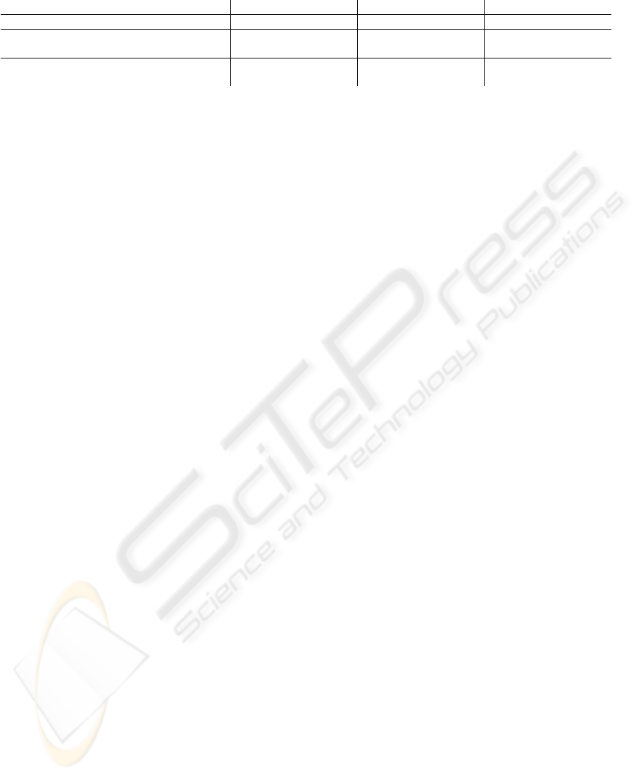
Table 3: Result summary.
Command Interface 1 Command Interface 2 Command Interface 3
Total time to execute 6,735.3s (≈112m) 392.3s (≈6.5m) 2,863.6s (≈48m)
‘Command‘ implementation identification 6,580.7s (97.5%) 334.1s (85.1%) 2,778.0s (97.0%)
Other graph generation tasks 154.7s (2.5%) 58.2 (14.9%) 85.5 (3.0%)
Random sample accuracy 100% 100% 100%
Selective EJB accuracy 25/29 (86.2%) 23/26 (88.5%) 19/23 (82.6%)
inaccurately retained) and false negatives (graph el-
ements inaccurately omitted). Table 3 displays the
time taken to generate the semantic graph and the
accuracy of the tested vertices for each of the three
slices produced. The time taken is separated into
two components in order to highlight that the ma-
jority of the time needed was spent recognizing one
type of dependency—identifying implementations for
a given ‘Command’ interface.
The graph generation process required almost 2
hours in the slowest trial, and almost 7 minutes in the
fastest trial; in the two longer trials, approximately
97% of the time was spent finding implementations
for ‘Command’ interfaces. The random sample of-
fered perfect accuracy in all 3 trials. Over the five se-
lected EJBs, 29 database table references were identi-
fied during the manual inspection. In the first trial, all
five EJBs were used, but only 25 of the 29 database
table references were identified. In the second trial,
only four of the five EJBs were used, and only 23 of
the 26 relevant database tables were linked. In the
third trial, a different set of four EJBs were used, and
only 19 of the 23 relevant tables were linked.
The performance of the graph generation process,
requiring almost 2 hours in the worst case and al-
most 7 minutes in the best case, implies that optimiza-
tions and further insight will be needed to generate
the graph for ‘online’ processing. This limitation is
almost entirely caused by the cost of identifying im-
plementations for a given interface, an operation that
requires scanning the roughly 30,000 classes compris-
ing the J2EE suite. The time can therefore be miti-
gated by implementing a more efficient algorithm for
performing this analysis or by implementing the se-
mantic graph persistence element of RMF.
The false negatives shown in Table 2 are particu-
larly interesting. When testing the algorithm for iden-
tifying database tables on which an EJB depends, we
encountered no errors of this type. After encounter-
ing these errors, we took the same EJBs that caused
a problem for the graph slicing analysis, and exe-
cuted the algorithm directly on those EJBs. When the
database table dependency algorithm was executed on
the EJBs directly, it gave 100% accuracy rate; the
same EJBs still showed false negatives when analysed
in the context of the graph slicing query, even though
the same code was used in both cases. This suggests
that the inaccuracies detected are a result of a coding
error, rather than of a limitation of the algorithm itself.
We identified one issue that may affect how rep-
resentative the results are of software systems in gen-
eral. IBM emphasizes architectural adherence. The
J2EE system engineers may adhere more closely to
architectural constraints and best practices than engi-
neers of other systems. If this is the case, then the
development of modelling components for an RMF
implementation may be more difficult for other soft-
ware systems than for the J2EE suite.
7 CONCLUSIONS
We studied the application of a semantic model to
modelling a software system comprised of many dif-
ferent kinds of document and the user-guided process-
ing of such a model to provide insight into the struc-
ture of the modelled system for the purpose of soft-
ware decomposition. Our research represents a first
step towards a larger goal: to determine the utility of
such a system for supporting software reengineering,
and software engineering in general.
The proposed Relationship Modelling Framework
(RMF) architecture can generate a semantic model of
a software system comprised of many different kinds
of document. We also provide evidence that the graph
slicing algorithm can be used to produce dependency
graphs that approximate a functional subset of the un-
derlying software system.
Possible future work includes optimizations to the
RMF prototype, specifically in maintaining and up-
dating the semantic graph across queries and in im-
proving the accuracy of the EJB-to-database table de-
pendency identification. A mechanism to automati-
cally generate semantic graph elements in the RMF
architecture, rather than being triggered from a query,
would also be a valuable addition.
Further study of the goal-oriented decomposition
process is needed beyond our preliminary validations,
both to establish its usefulness and to place it among
other reengineering procedures that could be under-
taken to achieve similar results.
IDENTIFICATION OF SOFTWARE SYSTEM COMPONENTS USING SEMANTIC MODELS AND GRAPH SLICING
11

We expect that further study of the utility of a se-
mantic model for graph slicing will identify other ar-
eas where such a model would be valuable, such as
checking or maintaining artifact consistency, visual-
ization, software design, and software testing. During
our validations, IBM engineers have already identi-
fied a number of additional use cases to investigate for
the RMF architecture, such as documentation gener-
ation, customization support, defect location, and de-
veloper education.
ACKNOWLEDGEMENTS
The authors wish to thank Jen Hawkins, Darsh Khu-
sial, and Ross McKegney for their invaluable help and
insights into this research. The work in this paper was
supported by an IBM Centre for Advanced Studies
Fellowship and by funding from the Natural Sciences
and Engineering Council of Canada.
REFERENCES
Bass, L., Clements, P., and Kazman, R. (2003). Software
Architecture in Practice. Addison-Wesley, Boston,
MA, 2 edition.
Bauer, M. and Trifu, M. (2004). Architecture-Aware Adap-
tive Clustering of OO Systems. In CSMR’04: Pro-
ceedings of the Eighth Euromicro Working Conference
on Software Maintenance and Reengineering, page 3,
Washington, DC, USA. IEEE Computer Society.
Beck, J. and Eichmann, D. (1993). Program and Interface
Slicing For Reverse Engineering. In ICSE ’93: Pro-
ceedings of the 15th international conference on Soft-
ware Engineering, pages 509–518, Los Alamitos, CA,
USA. IEEE Computer Society Press.
Ceccato, M., Marin, M., Mens, K., Moonen, L., Tonella, P.,
and Tourwe, T. (2006). An Appying and Combining
Three Different Aspect Mining Techniques . Software
Quality Journal, 4(3):209–231.
Egyed, A. and Medvidovic, N. (2000). A Formal Approach
to Heterogeneous Software Modelling. Technical re-
port, University of Southern California.
Finnigan, P. J., Holt, R., Kalas, I., Kerr, S., Kontogiannis,
K., Muller, H., Mylopoulos, J., Perelgut, S., Stanley,
M., and Wong, K. (1997). The Software Bookshelf.
IBM Systems Journal, 36(4):564–593.
G. Balakrishnan and R. Gruian and T. Reps and T. Teit-
elbaum (2005). CodeSurfer/x86 – A Platform for
Analyzing x86 Executables, (tool demonstration pa-
per). In Proc. Int. Conf. on Compiler Construction.
Springer-Verlag.
GrammaTech, Inc. (2007). GrammaTech:
Products: CodeSurfer. Web page.
http://www.grammatech.com/products
/codesurfer/overview.html.
Group, R. C. W. (2007). Resource Description Framework
(RDF). Web page. http://www.w3.org/RDF/.
Lehman, M. M. (1996). Laws of Software Evolution Re-
visited. In EWSPT ’96: Proceedings of the 5th Eu-
ropean Workshop on Software Process Technology,
pages 108–124, London, UK. Springer-Verlag.
Lung, C.-H., Xu, X., and Zaman, M. (2005a). Software
Architecture Decomposition Using Attributes. Inter-
national Journal of Software Engineering and Knowl-
edge Engineering, Special Issue on Selected Papers
from ICSEKE 2005.
Lung, C.-H., Zaman, M., and Goel, N. (2005b). Reflec-
tion on Software Architecture Practices - What Works,
What Remains to Be Seen, and What Are the Gaps.
WICSA, 0:221–222.
Lyle, D. J. R. and Wallace, D. R. (2007). Un-
ravel Program Slicing Tool. Web page.
http://hissa.nist.gov/project/unravel.html.
Marciniak, J. J., editor (1994). Encyclopedia of Software
Engineering, volume 1, pages 382–394. John Wi-
ley and Sons, Inc., 605 Third Avenue, New York, NY
10158–0012.
Mitchell, B. S. and Mancoridis, S. (2002). Using Heuris-
tic Search Techniques to Extract Design Abstractions
from Source Code. In 6th Annual Genetic and Evo-
lutionary Compting Conference (GECCOS02), pages
1375–1382.
M
¨
uller, H. A., Tilley, S. R., Orgun, M. A., and Corrie,
B. D. (1992). A Reverse Engineering Environment
Based on Spatial and Visual Software Interconnection
Models. In Proceedings of the Fifth ACM SIGSOFT
Symposium on Software Development Environments,
pages 88–98.
Ning, J., Engberts, A., and Kozaczynski, W. (1993). Recov-
ering Reusable Components From Legacy Systems
By Program Segmentation. In Proceedings of Working
Conference on Reverse Engineering, pages 64–72.
Object Management Group (2006). Reference Model for
Service Oriented Architecture 1.0. Technical report,
Object Management Group.
Salter, A. (2001). Semantic Modelling and a Semantic Nor-
mal Form. Technical report, Staffordshire University,
School of Computing.
Schmitt, L. (2007). Glossary. Web page.
http://www.cbu.edu/ lschmitt/I351/glossary.htm.
Sun Microsystems (2007). Java EE At a Glance. Web page.
http://java.sun.com/javaee/index.jsp.
Weiser, M. (1981). Program Slicing. In Proceedings of the
5th Interational Conference on Software Engineering,
pages 439–449, New York. IEEE.
ICSOFT 2009 - 4th International Conference on Software and Data Technologies
12
