
THREEDIMENSIONAL TRACKING USING OBJECT DEFOCUS
In Twodimensional Scanning Electron Microscope Images
Christian Dahmen
Division Microrobotics and Control Engineering, University of Oldenburg, Oldenburg, Germany
Keywords:
Image processing, Object tracking, Depth estimation, Focus analysis.
Abstract:
This paper proposes a tracking algorithm for the extraction of threedimensional position data from SEM im-
ages. An algorithm based on active contours with region-based minimization is chosen as basis for twodi-
mensional tracking. This algorithm is then augmented by the incorporation of defocus analysis to estimate
the out-of-focus displacement of the object. To solve the ambiguity of the out-of-focus displacement, the
astigmatism of the SEM images is used. The separate calculation of variances for the rows and columns of
the image enables a successful direction estimation. With the information on the direction, the out-of-focus
displacement and the working distance of the acquired image, the distance of the object to the electron gun can
be calculated. In combination with the twodimensional part of the tracking, a full threedimensional coordinate
set is generated. The approach is tested and evaluated using a positioning setup and the principal feasibility is
shown.
1 INTRODUCTION
The SEM has been widely used as a imaging tool
for the automated handling of micro- and nanoscale
objects (see e.g. (Fatikow, 2007)). While there
have been many manipulations executed manually,
and with the necessary experience these manipula-
tions have a high success rate, fully automated han-
dling and manipulation of micro- or even nanoscale
objects in the SEM still is very rarely encountered.
The problems which have to be solved are manifold
and not easy to handle. Integrated sensors in the actu-
ators or the setup may deliver some information about
the positions of end-effectors and tools, and enable
estimates about the position of objects to be manip-
ulated. The real actual position information of ob-
jects or tools though is difficult to recover from this
data, because of various factors like thermal drift, play
or object interactions on the nanoscale. A specific
requirement for non-teleoperated processes is there-
fore the need for sensor feedback generation based
on SEM images. The SEM is the only sensor which
may deliver an overview over the whole scene, en-
abling the extraction of the positions of most or all
objects engaged in the manipulation. Only the SEM
determines these positions in a common coordinate
system, which makes it possible to evaluate relative
distances between the objects. One problem which is
crucial for the success of any automation approach is
the missing information about the position of objects
in z-direction, which means orthogonal to the image
plane. An example image illustrating the problem is
shown in figure 1.
Figure 1: A screenshot showing two objects having differ-
ent z-positions. One object is a silicon nanowire, the other
a deformed STM tip. The distance between the objects in
z-direction is not immediately visible.
72
Dahmen C. (2009).
THREEDIMENSIONAL TRACKING USING OBJECT DEFOCUS - In Twodimensional Scanning Electron Microscope Images.
In Proceedings of the 6th International Conference on Informatics in Control, Automation and Robotics - Robotics and Automation, pages 72-78
DOI: 10.5220/0002209200720078
Copyright
c
SciTePress

2 STATE OF THE ART
Different algorithms have been described in the lit-
erature extracting the twodimensional position of ob-
jects from SEM images for automation purposes. The
performance of these algorithms is good, making
first simple automation scenarios possible. The ap-
proaches used for twodimensional tracking on SEM
images and their possible extensions to 3D-tracking
will be summarized in the following.
One of the first and most simple approaches used
template matching as the basis of the algorithm (Siev-
ers and Fatikow, 2006). A template image is extracted
or loaded which contains the object to be tracked. The
template image is then cross-correlated with a search
area in the input image. The maximum value of the re-
sulting array is in the place where the template is most
likely to be found. Due to the use of cross correlation,
this approach is very robust against additive noise,
which is an advantage especially for fast scanned
SEM images. Problems of this approach are that the
algorithm is sensitive against certain changes in the
object appearance which may occur during handling
processes. Examples for these appearance changes
are rotation of the object, scaling of the object due to
magnification changes and partial occlusion by other
objects in the setup. Removing these weaknesses for
this method comes with increased computational ef-
fort so that a fast enough calculation is not always
possible. Extraction of the z-position is not featured
and cannot easily be added.
If instead of a template image a CAD model of
the object is available, it is possible to use rigid body
models to track the object in the SEM image (Kra-
tochvil et al., 2007). The implementation uses mea-
surement lines orthogonal to the model edges and
tries to fit the model to visible edges in the image.
Model edges which should be invisible are identified
and not used for the pose estimation. Though edge de-
tection is difficult in noisy SEM images, the approach
yields good results using advanced techniques for dis-
carding or outweighting false edges and through the
high number of measurement lines used. When three-
dimensional CAD-models are used, it is possible to
recover the threedimensional pose including in-plane
and out-of-plane rotations, except the z-position. The
extension for true threedimensional tracking relies on
a model of the SEM image projection to yield the z-
component of the position. This seems to be working
for low magnifications.
Another possibility is the use of active contours
or snakes (for details about this concept see (Blake
and Isard, 2000)), which do not rely on much pre-
existing knowledge about the object. Active contours
are parametrized curves in twodimensional space, that
means in the image plane. After coarse initialization
the contour is evolving to segment the object from the
scene. The contours are coupled with an energy func-
tion dependent on their shape or appearance, and on
the image data. This energy function is being mini-
mized by moving contour points or the contour as a
whole. The part dependent on the contour is called
internal energy, the part dependent on the image data
is the external energy. In the original formulation,
the external energy function was defined to be depen-
dent on the distance of the contour from edges in the
image, as explained in (Kass et al., 1988). For the
use with noisy SEM images, a region-based approach
(see (Sievers, 2006) and (Sievers, 2007)) has shown
to be useful. The external energy function here is de-
pendent on the region statistics and the noise charac-
teristics of the imaging source. The goal is to max-
imize the compound probability of the enclosed re-
gion. This approach has proven to be very robust to
additive noise, and is inherently robust against scaling
and rotation. If the contour minimization is restricted
to the euclidean transform space, robustness against
partial occlusion is added. Due to the model-free na-
ture of this approach, threedimensional tracking is not
immediately possible, but the coupling with focus-
based methods is principally possible and shows first
promising results in the SEM.
In this paper, the last tracking approach is taken
as a basis, and extended to use defocus analysis for
depth estimation. The extracted information is only
the z-position of the tracked object, without any struc-
tural information about the object. For the recovery of
threedimensional structure of objects, different meth-
ods may be used (see e.g. (Fernandez et al., 2006) or
(J
¨
ahnisch and Fatikow, 2007)).
3 PRINCIPLE
The principle of the twodimensional tracking has
been explained already in (Sievers, 2006). The impor-
tant aspect is that the active contour algorithm does
not only deliver the position information of the ob-
ject, but at the same time calculates a segmentation
of the object from the rest of the scene. This enables
further analysis of the enclosed object.
Due to the working principle of the SEM, only a
certain range around the set working distance is de-
picted sharp. Though this range is quite big in com-
parison to optical microscopes, defocusing is still evi-
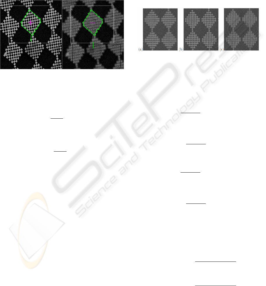
dent, as can be seen in figure 2. The defocusing in the
SEM has been used already in (Eichhorn et al., 2008)
to determine the z-position of objects by generating
THREEDIMENSIONAL TRACKING USING OBJECT DEFOCUS - In Twodimensional Scanning Electron Microscope
Images
73
a sharpness curve over a certain working distance
range. One drawback is the amount of time needed
to obtain this image sequence and therefore also the
disability to monitor dynamic processes. But by ana-
lyzing the sharpness of the object which is of interest,
it is also possible to directly conclude to the out-of-
focus displacement of the object, as has been recently
demonstrated for the SEM in (Dahmen, 2008).
Figure 2: Comparison of object in focus and out of focus.
The sharpness measure used here is the grey-level
variance
σ
2
(I, A(C)) =
1
N
A(C)
∑
p∈C
I(p) −
¯
I(A(C)) (1)
with
¯
I(A(C)) =
1
N
A(C)
∑
p∈A(C)
I(p)), (2)
and C the contour, A(C) the enclosed area and I
the image.
For the object enclosed by the contour this means
σ
2
(I(W D), A(C)) = Max ⇒ z(Ob ject) = W D (3)
with the working distance W D and the z-position
of the Object enclosed by the contour z(Ob ject).
One problem which persists after this analysis still
is that the out-of-focus displacement turns out to be
ambiguous. Two possibilities exist for the solution of
this problem, one assuming that the object is nearer
than the working distance, the other assuming that
the object is further away. This is a situation which
is not optimal for automation purposes. Though in
some cases the correct solution may be determined
by the setup and context knowledge, it is desirable to
determine the solution without additional information
apart from the image. For this case, a normally unde-
sired effect in SEM imaging may be taken advantage
of.
During normal use of the SEM, astigmatism is
something that is being diminished or removed by
astigmatism correction. Astigmatism in the SEM
leads to blurry images for the user. An important
property of astigmatism is that the sharpness is direc-
tion dependent. The focal points are different for two
perpendicular directions, as can be seen in figure 3. If
we name the two perpendicular directions w
0
and w
1
:
W D
W
0
6= W D
W
1
(4)
Figure 3: Astigmatism in the SEM, left and right slightly
out of focus, middle focused.
To take advantage of this, we calculate addition-
ally to the grey level variance of the image the grey
level variance of the rows and columns separately by
using
σ
2
x
(I, A(C)) =
∑
y
1
N
A(C)
(y)
∑
p(x,y)∈C
I(p) −
¯
I(A(C), y)
(5)
with
¯
I(A(C), y) =
1
N
A(C)
(y)
∑
p(x,y)∈A(C)
I(p)) (6)
and
σ
2
y
(I, A(C)) =
∑
x
1
N
A(C)
(x)
∑
p(x,y)∈C
I(p) −
¯
I(A(C), x)
(7)
with
¯
I(A(C), x) =
1
N
A(C)
(x)
∑
p(x,y)∈A(C)
I(p)) (8)
and C the contour, A(C) the enclosed area and I the
image.
The two values are normalized to their maximum,
which is determined during the initialization phase
(see section 4):
ˆ
σ
2
y
(I, A(C)) =
σ
2
y
(I, A(C))
max(σ
2
y
(I, A(C)))
(9)
and
ˆ
σ
2
x
(I, A(C)) =
σ
2
x
(I, A(C))
max(σ
2
x
(I, A(C)))
(10)
In this case we expect a working distance sweep
to generate two slightly displaced curves like depicted
ICINCO 2009 - 6th International Conference on Informatics in Control, Automation and Robotics
74
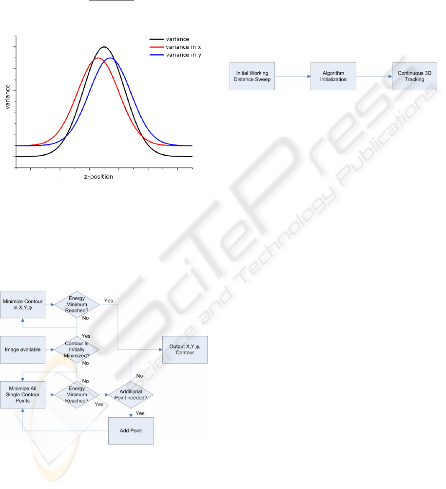
in figure 4, under the assumption that the object in the
image has suitable structure.
With the two curves having slightly displaced
maxima, we can estimate from the ratio of the two
values
r =
ˆ
σ
2
x
(I, A(C))
ˆ
σ
2
y
(I, A(C))
(11)
to which side the out-of-focus displacement occurs.
Figure 4: Expected curves for the different sharpness mea-
sures.
4 THE ALGORITHM
The twodimensional base algorithm is similar to the
active contour algorithm described in section 2. The
principle is depicted in figure 5. Important is that af-
Figure 5: The basic tracking algorithm for the twodimen-
sional part.
ter an initial free minimization, the tracker does only
translate and rotate the contour as a whole. This
is necessary to enable the out-of-focus estimator to
work, because else the enclosed area may change.
The same is valid for scaling, which is therefore dis-
abled in the algorithm. In order to enable continuous
threedimensional tracking, the algorithm has to be ini-
tialized like shown in figure 6. An initial working dis-
tance sweep is carried out to acquire the characteris-
tic curve of the tracked object. During this sweep, the
twodimensional tracking has to be enabled already.
After this, certain calculations and optimizations are
carried out on the acquired curves, e.g. it is made sure
that the curves are monotonic in sections. After the
data has been processed, the tracker can track contin-
uously until either object changes or imaging changes
require a reinitialization.
Figure 6: The initialization steps for the threedimensional
tracking.
The threedimensional tracking itself consists of
the twodimensional tracking algorithm, augmented
with a sharpness calculation component, an out-of-
focus displacement estimator and a direction estima-
tor, like shown in figure 7. The active contour tracker
delivers the twodimensional position and the segmen-
tation of the object. This segmentation is then used
to mask the original image. From the masked image,
the object sharpness is calculated using variance cal-
culation and the directional sharpness measures men-
tioned in the last section.
The variance value is used to estimate the out-of-
focus displacement by comparison with the data ac-
quired during initialization.
The directional sharpness values are used to es-
timate on which sidelobe of the initially acquired
sharpness curve the object is in the actual image. Af-
ter this is known, the information about the displace-
ment value and the displacement direction is com-
bined with the working distance at which the current
image was captured. The result is the estimated work-
ing distance at which the object is placed. This is then
joined with the position information from the twodi-
mensional tracking to generate a complete coordinate
set.
5 EXPERIMENTS
For the evaluation of the algorithm, the performance
has been tested in a setup inside the SEM. Target ob-
ject was a chessboard pattern as seen in figure 8. This
chessboard pattern has been put on a stub which is
mounted to a XYZ positioning setup using piezo slip-
stick actuated axes with internal position sensors. For
the experiment, the internal sensors of the axes were
read out and the acquired data joined with the track-
THREEDIMENSIONAL TRACKING USING OBJECT DEFOCUS - In Twodimensional Scanning Electron Microscope
Images
75
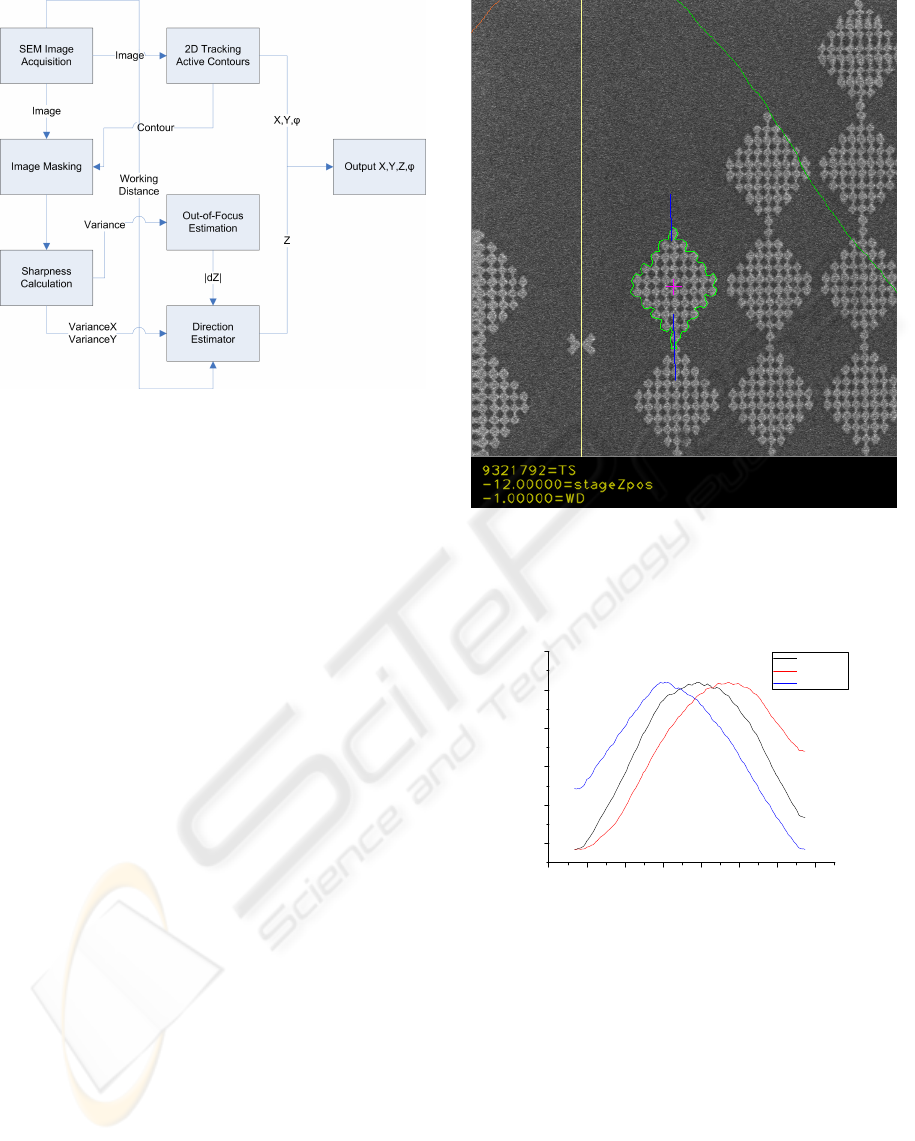
Figure 7: The complete 3D tracking algorithm in the initial-
ized state.
ing data. During the experiment the axes were moved
in closed loop mode using the internal sensors. The
movement was in a pattern to verify the algorithm per-
formance. All measurements have been executed at a
magnification of 800x and a scanspeed of 5 (frame av-
eraging of 2
5
frames) on a LEO scanning electron mi-
croscope. The twodimensional pattern of the move-
ment has a size of 21µm times 39µm. The pattern
has been repeated at the z-axis positions of 0.17mm,
0.256mm and 0.32mm.
6 RESULTS
The first result was the generation of the expected
curves from figure 4. The result can be seen in fig-
ure 9. The shift of the variance calculated in rows and
columns separately is clearly visible, which enables
the algorithm to work in the anticipated way, estimat-
ing the direction of the defocusing.
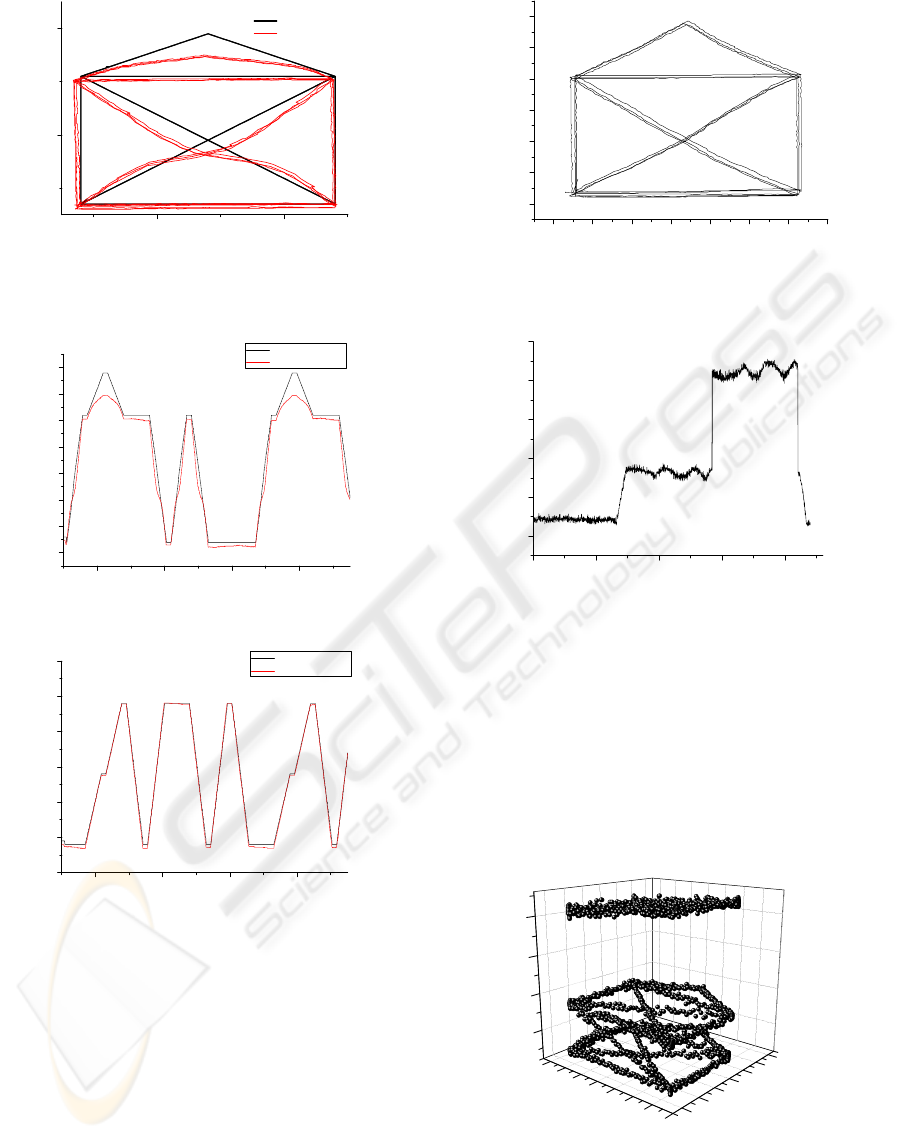
As can be seen in figure 10, the movement pat-
tern used incorporated movement along each axis as
well as in diagonal. Also visible is the distortion of
the shape in comparison to the acquired sensor val-
ues. The reason for this was determined in additional
tests to be a decalibrated sensor of one of the axes.
This sensor did not deliver the correct position value,
resulting in the closed loop control positioning to a
wrong real axis position.
In figure 11 and figure 12 this gets more obvious.
While the tracking position in figure 12 closely fol-
lows the sensor information, this is not the case in fig-
ure 11. Apart from the decalibrated sensor it can be
Figure 8: The structure used for the experiment, a chess-
board pattern mounted on a XYZ positioning setup. Visible
is the active contour tracking and segmenting one chess-
board block.
0 , 0 0 0 1 0 0 , 0 0 0 1 5 0 , 0 0 0 2 0 0 , 0 0 0 2 5 0 , 0 0 0 3 0 0 , 0 0 0 3 5 0 , 0 0 0 4 0 0 , 0 0 0 4 5
2 5 0 0
3 0 0 0
3 5 0 0
4 0 0 0
4 5 0 0
5 0 0 0
V a r i a n c e
z P o s
V a r i a n c e
V a r i a n c e X
V a r i a n c e Y
Figure 9: Measured curves for the variance and the variance
calculated in rows and columns separately.
stated that the twodimensional tracking is working.
In order to verify the tracking, the experiment was
repeated with a working and calibrated y-axis. The
twodimensional tracking can be seen in figure 13. The
shape of the movement is correct and the tracking is
working and stable.
Figure 14 shows the determined z-Position from
the tracking algorithm. Visible is that there is a certain
systematic error in the tracked position, as the calcu-
lated values deviate from the expected values. The
set working distance of the SEM is in the middle of
the working distance range shown in figure 14, at the
ICINCO 2009 - 6th International Conference on Informatics in Control, Automation and Robotics
76
9 , 7 2 9 , 7 4
1 0 , 2 0
1 0 , 2 2
Y - p o s i t i o n [ m m ]
X - p o s i t i o n [ m m ]
s e t p o s i t i o n
t r a c k e d p o s i t i o n
Figure 10: Tracked X-Y position of the chessboard pattern.
The distorted shape and deviations are due to a decalibrated
actuated axis for the y-direction.
1 0 , 1 8 5
1 0 , 1 9 0
1 0 , 1 9 5
1 0 , 2 0 0
1 0 , 2 0 5
1 0 , 2 1 0
1 0 , 2 1 5
1 0 , 2 2 0
y - p o s i t i o n [ m m ]
t i m e
a x i s p o s i t i o n
t r a c k e d p o s i t i o n
Figure 11: The tracked and set y-position over time.
9 , 7 0
9 , 7 1
9 , 7 2
9 , 7 3
9 , 7 4
9 , 7 5
9 , 7 6
x - p o s i t i o n [ m m ]
t i m e
a x i s p o s i t i o n
t r a c k e d p o s i t i o n
Figure 12: The tracked and set x-position over time.
value 0.28. The problem which occurs here is that the
algorithm is most accurate not in the point of maxi-
mal focus, but within a certain range on the sidelobes
of the sharpness curve. As can be seen in figure 9,
the sharpness curve is relatively flat around the max-
imum. In this interval around the maximum, small
changes in detected sharpness, which may also oc-
cur due to time variant behavior of the SEM imaging
process or due to certain changes in the surrounding
setup, will result in large errors in the estimated out-
of-focus displacement. This explains also not only
the big deviation from the axis set value, but also the
large amount of variation during the movement on the
y - p o s i t i o n
x - p o s i t i o n
Figure 13: Tracked X-Y position of the chessboard pattern
in the repeated measurement.
0 , 1 5
0 , 2 0
0 , 2 5
0 , 3 0
0 , 3 5
0 , 4 0
z - p o s i t i o n [ m m ]
T i m e
Figure 14: The tracked z-position over time.
same z-position. So it has to be stated that the opti-
mal working condition for this algorithm is a slightly
defocused image.
In figure 15 the tracking result can be seen in three
dimensions. The movement pattern is qualitatively
visible, though the tracking in z-direction is not as
good as in the image plane. Still the goal of the algo-
rithm design has been reached, an estimate has been
calculated for the z-position of the object which is
principally useable.
Z A x i s
Y A x i s
X A x i s
Figure 15: The tracked movement in 3D.
THREEDIMENSIONAL TRACKING USING OBJECT DEFOCUS - In Twodimensional Scanning Electron Microscope
Images
77

7 SUMMARY
In this paper a threedimensional tracking algorithm
for the tracking of objects in the SEM has been pre-
sented. The algorithm takes advantage of the image
defocusing which is evident when objects leave the
focal plane. A twodimensional tracking algorithm
based on active contours with a region-based mini-
mization has been taken as the base algorithm. Added
extensions include the segmentation of the object and
the consecutive sharpness calculation. Additionally
the variance of the rows and columns is calculated
separately for determining the direction of the defo-
cusing. This enables the analysis of the sharpness in
different directions. If the image contains astigma-
tism, it is possible to estimate if the image focal plane
lies in front of or behind the object. Experiments
have shown that this approach is working and after
an initialization phase qualitatively delivers a three-
dimensional position information. The z-position still
contains a systematic error, which is most influential
around the best focused point. This error has to be
diminished by further analysis and change and op-
timization of the implementation. Overall the feasi-
bility of this threedimensional tracking algorithm has
been shown.
REFERENCES
Blake, A. and Isard, M. (2000). Active Contours. Springer.
Dahmen, C. (2008). Focus-based depth estimation in the
sem. In Proceedings of the International Sympo-
sium on Optomechatronic Technologies 2008, volume
7266, page 72661O. SPIE.
Eichhorn, V., Fatikow, S., Wich, T., Dahmen, C., Sievers,
T., Andersen, K., Carlson, K., and Bøggild, P. (2008).
Depth-detection methods for microgripper based cnt
manipulation in a scanning electron microscope. Jour-
nal of Micro-Nano Mechatronics. accepted.
Fatikow, S. (2007). Automated Nanohandling by Micro-
robots.
Fernandez, J., Sorzano, C., Marabini, R., and Carazo, J.
(2006). Image processing and 3-D reconstruction in
electron microscopy. Signal Processing Magazine,
IEEE, 23(3):84–94.
J
¨
ahnisch, M. and Fatikow, S. (2007). 3d vision feedback for
nanohandling monitoring in a scanning electron mi-
croscope. International Journal of Optomechatronics,
1(1):4–26.
Kass, M., Witkin, A., and Terzopoulos, D. (1988). Snakes:
Active contour models. International Journal of Com-
puter Vision, 1(4):321–331.
Kratochvil, B. E., Dong, L. X., and Nelson, B. J. (2007).
Real-time rigid-body visual tracking in a scanning
electron microscope. In Proc. of the 7th IEEE Conf.
on Nanotechnology (IEEE-NANO2007), Hong Kong,
China.
Sievers, T. (2006). Global sensor feedback for automatic
nanohandling inside a scanning electron microscope.
In Proc. of 2nd I*PROMS NoE Virtual International
Conference on Intelligent Production Machines and
Systems, pages 289–294.
Sievers, T. (2007). Echtzeit-Objektverfolgung im
Rasterelektronenmikroskop. PhD thesis, Univer-
sity of Oldenburg.
Sievers, T. and Fatikow, S. (2006). Real-time object track-
ing for the robot-based nanohandling in a scanning
electron microscope. Journal of Micromechatronics,
3(3-4):267–284.
ICINCO 2009 - 6th International Conference on Informatics in Control, Automation and Robotics
78
