
FROM BENDING TO LINEAR MOVEMENT
A Linear Actuation Mechanism based on Conducting Polymer Actuators
Elise T. Burriss, Gursel Alici
University of Wollongong, School of Mechanical, Materials and Mechatronic Engineering, Australia
Geoffrey M. Spinks, Scott McGovern
University of Wollongong, School of Mechanical, Materials and Mechatronic Engineering, Australia
Keywords: Electroactive polymer actuators, Linear actuation, Kinematic design.
Abstract: The objects of this study are (i) to establish a linear actuation system based on the bending movement of
conducting polymer actuators, which operate in air, and (ii) to develop a model to predict the linear
displacement and force output of the actuation system, and employ the model to characterise the optimum
values of the system design parameters. The linear actuation system is based on a five bar parallel
mechanism with equal link lengths and a zero-length ground link, which is articulated through two bending
type polymer actuators. Kinematic and force analyses of the mechanism including numerical results are
presented, and its payload handling ability was experimentally evaluated. Experimental results presented
demonstrate that the linear actuation system can generate linear movement accurately and a rectilinear force
as a result of two bending type polymer actuators. This mechanism is offered as a lightweight, low power
consuming motion and force transmission system.
1 INTRODUCTION
Conducting polymers are favourable as actuators
due to their low actuation voltage, high force output
relative to their weight, good strain properties, light
weight, simple structure and silent motion. The
common materials used for actuators are Ionic
Polymer Metal Composite (IPMC), and electroactive
polymers (EAPs) such as Polypyrrole (PPy) and
Polyaniline (PANI) (Thompson, 2007).
Disadvantages of polymer actuators include low
speed of response, cyclic fatigue and non-linearity,
which increases difficulty in modelling and
controlling the actuator (Alici, Metz & Spinks 2005,
Eamex nd).
Bending actuators have been successfully used
in applications where a nonlinear motion is required,
such as a fin in an artificial fish (Alici et. al, 2007)
and robotic fingers (Alici & Huynh, 2007).
However, the bending motion may limit the control
of actuators along a linear path. Conducting
polymers have been used as actuators in applications
such as medical devices, toys, digital camera
accessories and artificial muscles for robots as
developed by Eamex 2008. Various PPy linear
actuator designs have been investigated, including
the PPy linear design by Otero, Cortes & Vazquez
Arenas (2007), in which two PPy films were
connected in parallel and immersed in a LiClO
4
aqueous solution, were able to produce a
displacement of 60% of the actuator length in the
longitudinal direction of the actuator. The use of
linear actuators in air may provide an alternative
when encapsulation of the electrolyte is not feasible.
Yamakita et. al (2004) have developed an IPMC
linear actuator for use in a biped walking robot. PPy
actuators are used in applications where the oxidised
or reduced position is maintained under a constant
voltage, for which IPMC is not suitable as it will
return to its original position. To overcome this
limitation of IPMC, Thompson (2007) adopted the
design by Yamakita et al. using polypyrrole film as
the active layers of a multi-layer actuator structure.
Two methods of connecting the PPy film together to
produce the linear design were employed by
Thompson: (i) masking part of the film during PPy
growth to create a flexible, electrically conductive
hinge; (ii) electrically connecting the film with Cu
13
T. Burriss E., Alici G., M. Spinks G. and McGovern S.
FROM BENDING TO LINEAR MOVEMENT - A Linear Actuation Mechanism based on Conducting Polymer Actuators.
DOI: 10.5220/0002166000130020
In Proceedings of the 6th International Conference on Informatics in Control, Automation and Robotics (ICINCO 2009), page
ISBN: 978-989-8111-99-9
Copyright
c
2009 by SCITEPRESS – Science and Technology Publications, Lda. All rights reserved

tape, held in place with NdFeB magnets. This study
implements the design investigated by Thompson
using the second method of connecting the film
together, as the method of masking allows the
actuator to produce a clover-like shape under
actuation, which impedes control and stability of the
actuator. However, limitations arising through the
use of Cu tape may include oxidation of the Cu,
converting the tape to an insulator, thus limiting the
actuation of the PPy components connected by
copper tape. For optimisation of the PPy film in this
study, the geometry of PPy bending actuators is
limited to 50µm thickness and 4mm width as the
charge distribution has been found to be no longer
uniform at thicknesses greater than 50-60µm and
curling is prominent at widths greater than 4mm,
producing an increase in elastic stiffness of the
actuator (Alici, Metz & Spinks 2005, Metz, Alici &
Spinks 2006). These limitations are expected to be
also evident in PPy linear actuators.
A significant amount of work to determine the
performance of bending PPy actuators has been
previously conducted (Alici & Huynh 2007, Metz,
Alici & Spinks 2006, John, Alici & Cook 2008).
However, the complexity and greater degree of
variability in a linear actuator means that the
performance of a bending actuator may not directly
translate to linear actuators. The modelling of linear
actuators is necessary to accurately predict the force,
displacement and work outputs for control of the
actuator in practical applications. Modelling and
optimisation work on PPy bending actuators by
Alici, Metz & Spinks (2005), in which a
mathematical model to calculate the expected
bending behaviour of PPy bending actuators was
developed, and suggests that as the length of the
actuator decreases, force output increases. This
study has investigated the effect of the length of PPy
components in linear actuators to determine if length
has a similar effect on outputs in linear actuators.
Combinations of 2mm, 3mm, 4mm wide and 10mm,
15mm and 20mm long linear actuators, where the
length refers to the length of each component, were
experimentally evaluated for force and displacement
outputs. It was found that an increase in the length of
the PPy links in the linear actuators allowed a
greater range of motion, whilst shorter and wider
actuators lifted greater loads. The linear actuators
were also compared to bending actuators of
corresponding dimensions and it was found that the
bending actuators had a greater range of motion and
the linear actuators lifted heavier loads. As the
proposed linear actuation mechanism converts the
rotational work into the linear work, ideally they are
equal to each other, it is expected that while the
displacement is decreasing, the force is increasing,
and vice versa.
2 FUNCTIONING PRINCIPLE OF
LINEAR ACTUATION SYSTEM
As the polymer actuators considered in this study are
cantilevered from one end, they generate a rotary
(bending) type motion. This is analogous to a single
jointed crank motion. A single degree of freedom
mechanism such as a four-bar mechanism does not
allow control the output motion. With this in mind, a
five-bar mechanism which needs two inputs (two
bending type polymer actuators) is one of the multi
crank mechanisms having practical importance,
especially for following any arbitrary trajectory
precisely (Alici, 2000). This mechanism serves as a
bending to-linear motion converter; converting
bending angle into a linear movement, and bending
moments into linear forces.
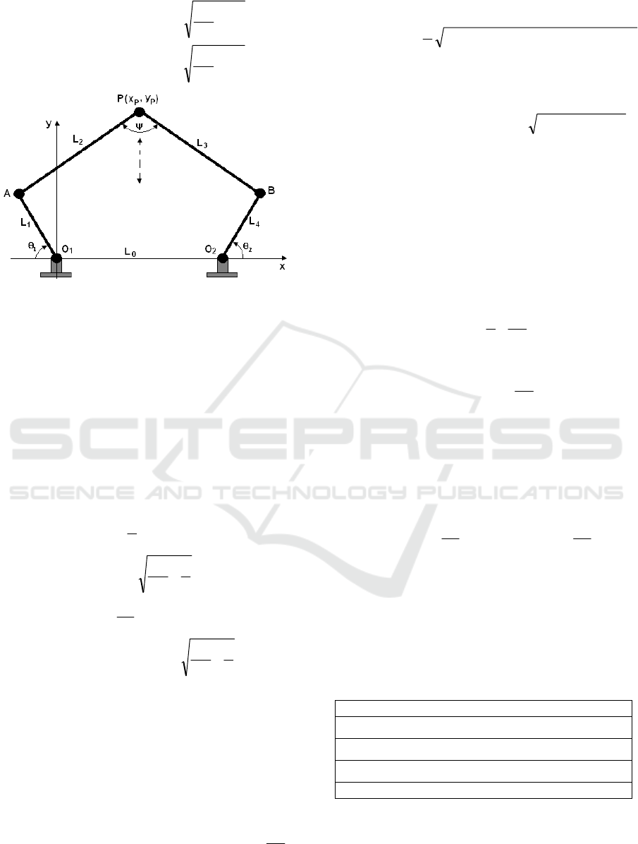
2.1 Kinematic Analysis
The topology of the mechanism is depicted in Figure
1, where it is assumed that the mechanism links are
rigid for the sake of generating a pseudo-rigid-body-
model for the size and operation optimization of this
linear motion mechanism. The joints connected to
the frame are the active ones. The others are passive.
For the joint inputs
1
θ
and
2
θ and the specified link
lengths
43210
L,L,L,L,L the analytical expressions
for the coordinates of the output point P are obtained
using the following algorithm (Alici, 2000):
()
,jsinLicosLLL
,jsinLicosLL
242405
11111
θ+θ+=
θ+θ=
(1)
,jDiCLBORAB
11
+=−== (2)
,DCR
,LBOD,LBOC
22
y1
y
1x1
x
1
+=
−=−=
(3)
,
R2
LRL
Q
2
2
3
22
2
−+
=
(4)
The coordinates
(
)
PP
y,x of the output point P are;
ICINCO 2009 - 6th International Conference on Informatics in Control, Automation and Robotics
14
,Q
R
L
CDQyy
,Q
R
L
DCQxx
2
2
2
2
AP
2
2
2
2
AP
−++=
−−+=
(5)
Figure 1: Proposed linear actuation module based on a
parallel five-bar mechanism.
Depending on the link lengths, the expression in
the square-root can become negative, which suggest
that some kinematic design constraints are not
satisfied. For a linear motion output, the output point
can be constrained to move in a rectilinear fashion.
This requires that
21
θ
=θ AND
41
LL = AND
32
LL = . Such a mechanism will convert all of its
rotary work into the linear work - an efficient motion
converter. The analytical expressions for the output
point of such a linear motion module are obtained as
()
[]
()
()
()
[]
4
1
R
L
coscosLL
sinsin
2
L
sinLy
4
1
R
L
sinsinL
coscosLL
2
1
cosLx
2
2
2
1210
12
1
11P
2
2
2
121
121011P
−θ+θ++
θ−θ+θ=
−θ−θ−
θ+θ++θ−=
(6)
where
()
()
[]
21
2
1
1210
2
0
2
cos1L2
coscosLL2LR
θ+θ++
θ+θ+=
(7)
Depending on the link length of the mechanism,
Eq.6 simplifies to
i)
For
21
LL = and ⇒θ=θ
21
2
L
x
0
P
=
and
1
22
1110
2
0
2
1
11P
cos4L-cosL4L-L-4L
2
1
sinLy
θθ+
θ=
ii)
For 0L
0
=
and ⇒θ=θ
21
0x
P
=
and
1
22
1
2
211P
cosLLsinLy θ−+θ=
iii)
For 0L
0
=
,
21
LL = and ⇒θ=θ
21
0x
P
=
and
11P
sinL2y θ=
When choosing the link sizes, it is important for
effective force transmission to minimize the
variation of the transmission angle
ψ
from 90
0
; the
acceptable range is
00
4090 ∓ (Alici, 2004). It is
mathematically expressed as
2
2
L
R
2
1
1cos
⎟
⎟
⎠
⎞
⎜
⎜
⎝
⎛
−=ψ (8)
For
00
13050 ≤ψ≤ , 8126.1
L
R
845.0
2
≤
⎟
⎟
⎠
⎞
⎜
⎜
⎝
⎛
≤ . With
reference to Eq.8, for a given
0
L and
1
L , the range
of
2
L satisfying the effective transmission angles
can be calculated. It must be noted that
0
L should
be greater than
1
L to prevent any physical
interference among the mechanism links. A practical
ratios of
0.3
L
L
5.1
1
0
≤
⎟
⎟
⎠
⎞
⎜
⎜
⎝
⎛
≤ and 0.2
L
L
0.1
1
2
≤
⎟
⎟
⎠
⎞
⎜
⎜
⎝
⎛
≤
should result in proportionate link lengths and
transmission angles. For the data shown in Table 1,
the transmission angle and the vertical movement of
the linear actuation module are calculated and
presented in Figure 2.
Table 1: Numerical values of the parameters for the
exemplary results shown in Figure 2.
Parameters
mm40L
0
=
mm20LL
31
=
=
mm22LL
42
=
=
00
2
1
115to90
=
θ
=
θ
The corresponding generalized relationship
between rate of change
12
T
θθ
⎡⎤
Θ=
⎣⎦
of the input
bending angles and the output velocity vector
FROM BENDING TO LINEAR MOVEMENT - A Linear Actuation Mechanism based on Conducting Polymer Actuators
15
[]
T
PP
yxX
=
is given by (Alici & Shirinzadeh,
2005)
()()
Θ=Θ
⎥
⎦
⎤
⎢
⎣
⎡
θθ∂
∂
θθ∂
∂
=
J
,
y
,
x
X
T
21
P
21
P
(9)
where J is the mechanism Jacobian matrix.
90 95 100 105 110 115
25
30
35
40
Vertical Position y
P
(mm)
90 95 100 105 110 115
60
80
100
120
140
Input Bending Angles,
θ
1
and
θ
2
(degree)
Transmission Angle (degree)
Figure 2: Variation of the vertical position of the output
point P and the transmission angle with the input bending
angles. The net vertical distance is 7.6858 mm.
2.2 Force Analysis
Assuming that two active links AO
1
and BO
2
made of electroactive polymers generate bending
moments
1
M and
2
M , which act on the actuation
module in the opposite directions. Assume that the
output point P can apply a planar force vector of
jFiFF
yxp
+= to the environment to realise a
functional task. Please recall that the mechanism
converts the work in the bending coordinates
Θ
into
the work in linear coordinates X. These two works
are ideally equal to each other.
90 95 100 105 110 115
0
0.1
0.2
0.3
0.4
0.5
0.6
0.7
0.8
Input Bending Angles,
θ
1
and
θ
2
(degree)
Vertical Force F
Py
(mN)
Figure 3: Variation of the vertical force component of the
output point P with the input bending angles. The net
vertical force is 0.6837 mN. The horizontal component of
the force is zero.
Using the duality between the generalized
relationships for motion and force transfer between
the actuation and output spaces, the following force
relationship is obtained (Alici &
Shirinzadeh, 2005);
MJFFJM
T
PP
T −
=⇒= (10)
where
[
]
T
yxP
FFF = and
[]
T
21
MMM = and
T
(.)
denotes transposition. For the data in Table 1 and
[
]
T
11M =
Nmm, the force output at point P is
calculated using Eq.10 and is presented in Figure 3.
Because the mechanism link lengths are chosen such
that it can generate a vertical movement, the
mechanism will not create any horizontal force
component. These kinematic and force analyses
suggest that it is possible to optimize the topology of
the mechanism for an efficient motion and force
transmission.
3 CONDUCTING POLYMER
ACTUATORS: SYNTHESIS
AND ACTUATION PRINCIPLE
The PPy film was manufactured by combining a
solution of 0.1M pyrrole monomer with 0.1M
lithium triflouromethanesulfonimide (Li
+
TFSI
−
) in
propylene carbonate (PC) with 1 % H
2
O, degassed
with nitrogen gas and stirred for 15 minutes. This
solution was used to grow the PPy onto a gold
sputter coated, 0.45
μm Millipore Immobilon-P
porous poly(vinylidene fluoride) (PVDF) film by
electrodeposition over a period of 12 hours at -33
o
C
with a current density of 0.1mA.m
-2
. After
polymerization, the film was washed in acetone and
then resoaked in a 0.1M LiTFSI electrolyte and then
stored away from oxygen. Actuators were then cut
to desired size using a scalpel and were limited to
size by the area of the 40mm x 55mm film. The
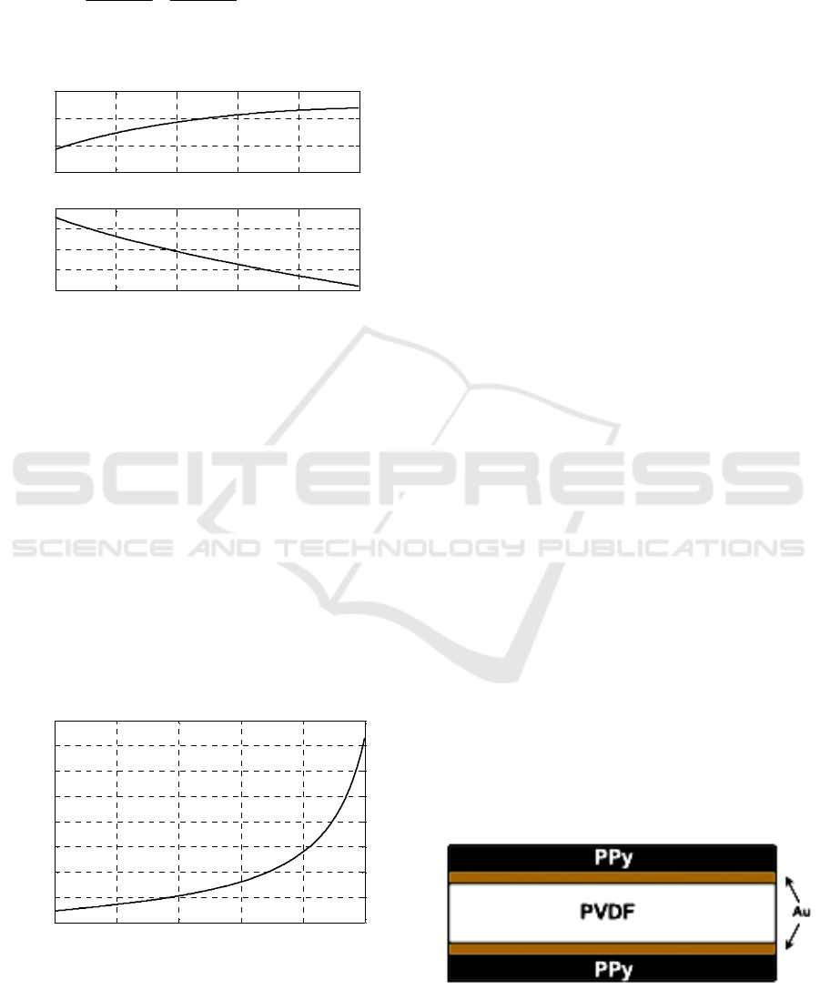
resulting film consists of two PPy outer layers and
two gold layers separated by a PVDF core is shown
in Figure 4.
Figure 4: General structure of trilayer polymer actuator.
ICINCO 2009 - 6th International Conference on Informatics in Control, Automation and Robotics
16
After doping with electrolyte, both the PPy
layers of a bending actuator become partially
oxidised (Figure 5a) and upon application of a
positive voltage, one of the polymer layers is highly
oxidized and the other is reduced. In an attempt to
neutralise the charge imbalance, ions transfer from
the electrolyte into the polymer layers. In LiTFSI
doped actuators, TFSI
-
anions move into interstitial
spaces in the polymer backbone of the oxidized
layer, causing it to expand. Simultaneously, the
opposing polymer film is reduced and contracts by
removing TFSI
-
ions, overall creating a bending
motion (Figure 5b.) By applying a square wave
voltage, the actuator is allowed to return it to its
original position and continue to bend through the
neutral position so that the actuator may bend
alternately in both directions.
Figure 5: Schematic of PPy actuator doped in LiTFSI (a)
partially oxidised (b) under an applied voltage.
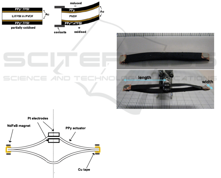
To produce the linear actuators, two pieces of PPy
film cut to equal dimensions were connected
together in parallel at their tips with copper tape and
two Ø 3mm × 0.5mm neodymium iron boron
(NdFeB) magnets one either side of each tip
(Figures 6-7.) Once placed between the electrodes,
the PPy configuration effectively produces four PPy
components, with the length referred to throughout
this paper as the length depicted in Figure 7b.
Figure 6: Configuration of the linear PPy actuator with Cu
tape and NdFeB magnets.
Under an applied voltage, it was observed that the
PPy linear actuator produced the shape as shown in
Figure 8. In this case, the outer PPy layer of the
upper components is oxidised and the inside layer is
reduced, and under no constraints, almost uniform
curvature may be experienced. The lower
components may be activated; however the possible
oxidation of the Cu tape suggests that the lower
components remain either inactivated. This linear
design restricts the bending motion of the actuators
due to the presence of the magnets used to clamp the
copper tape to the actuators (Figure 8). For the
shorter lengths, a greater percentage of the actuator
is affected by the clamping induced by the magnets
and as a result, the actuator has a more elongated
appearance (Figure 9). Due to this elongation, it
doesn’t move as far in the vertical direction as it
potentially could. To overcome this limitation,
another method of electrically connecting the upper
and lower actuator components that does not restrict
the motion is necessary. For this to be possible, the
electrical connection must be flexible and able to
bond to the actuator without the assistance of
magnets. Although the magnets restrict motion, they
do provide some stability which is important in
attempting to control the actuator.
(a)
(b)
Figure 7: Linear PPy actuator in neutral position.
4 PERFORMANCE
CHARACTERISATION
RESULTS
Linear actuators shown in Figures 6-7 with link
lengths of 10mm, 15mm, 20mm and widths of 2mm,
3mm, 4mm were manufactured and tested under a
series of applied loads. Loads were added to the
bottom tip of the actuators and the overall
displacement of the base tip was measured visually
using a grid paper, as illustrated in Figure 10a. The
initial load used was the non-magnetic wire hook
and a 0.266g NdFeB magnet glued to its base
(Figure 10b), with incremental loads applied by
FROM BENDING TO LINEAR MOVEMENT - A Linear Actuation Mechanism based on Conducting Polymer Actuators
17
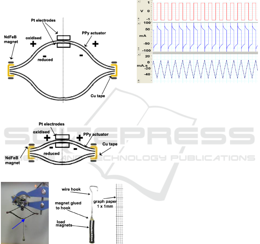
adding magnets of either 0.266g or 0.54g to the base
of the wire hook. Voltage was maintained at +/-1V
to avoid over-oxidation and reduce the variation in
results that may arise due to early onset of fatigue.
The frequency of the square voltage inputs was held
constant for all experiments at 0.5Hz to allow
sufficient response time. Typical voltage, current
and charge data recorded by the datalogging system
used is presented in Figure 11.
Figure 8: Shape of actuator under actuation.
Figure 9: Shape of shorter actuators under actuation.
(a) (b)
Figure 10: (a) PPy linear actuator with a load. (b) Wire
hook; used to separate magnet loads from magnets on the
actuator.
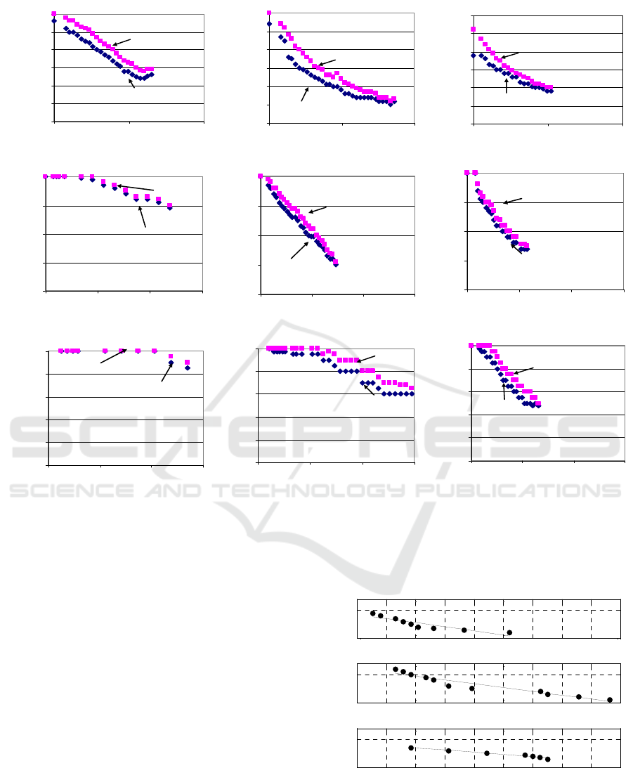
Figures 12(a)-(i) provide an overview of the base
tip position in extended and contracted positions
under given applied loads, with the electrode
contacts as the reference point. In all actuators, as
the load increases the position of the base tip below
the reference point also increases. Generally, as the
width decreases the position below the electrode
increases and is more evident in the 15mm long
actuators. As width increases, the actuator becomes
stiffer which allows a smaller deflection below the
reference point under a load than an actuator of a
small width.
Figure 11: Example voltage, current and charge input data
for 20mm x 2mm linear PPy actuator at 0.5Hz.
Displacement increases and then decreases for
increasing load as shown in Figure 12(d)-(i) for the
15mm and 10mm long actuators. This behaviour is
because under no load, the actuators are restricted in
their movement by the magnets clamping the Cu
tape in place. The clamping effect has a greater
impact on shorter actuators because, as a percentage,
a greater proportion of the actuator is restricted than
longer actuators. Under applied loads, the shorter
actuators are able to move because the load forces
the actuator base tip to be displaced to lower than
the original position, and under an applied voltage
the actuator attempts to return to the original
position and produces an upward motion.
For this
reason, the shorter actuators may only be suitable for
applications requiring a pulling load, and if shorter
actuators are required for pushing, then another
method of connecting the actuators that provides less
restriction on motion is required.
A comparison of load and displacement output
between the linear and cantilever actuators of
corresponding length has revealed that the cantilever
actuators provide a greater range of motion in the
vertical direction, while the linear actuator lifted
heavier loads. The linear actuators are effectively 4
times the volume of their corresponding bending
actuator.
Base tip of
actuator
ICINCO 2009 - 6th International Conference on Informatics in Control, Automation and Robotics
18
Load v position, 4 x 20m m
-30
-25
-20
-15
-10
-5
0
0510
Load (mN)
contracted
extended
Position of base tip
below electrode (mm)
Load v position, 3 x 20mm
-30
-25
-20
-15
-10
-5
0
0510
Load
(
mN
)
contracted
extended
Position of base tip
below electrode (mm)
Load v position, 2 x 20mm
-30
-25
-20
-15
-10
-5
0
0510
Load (mN)
contracted
extended
Position of base tip
below electrode (mm)
(a) (b) (c)
Load v position, 4 x 15mm
-20
-15
-10
-5
0
0 5 10 15
L
oad
(
mN
)
contracted
extended
Position of base tip
below electrode (mm)
L
oa
d
v pos
iti
on,
3
x
15
mm
-20
-15
-10
-5
0
0 5 10 15
Load
(
mN
)
contracted
extended
Position of base tip
below electrode (mm)
L
oa
d
v pos
iti
on,
2
x
15
mm
-20
-15
-10
-5
0
0 5 10 15
Load (mN)
contracte d
extended
Position of base tip
below electrode (mm)
(d) (e) (f)
Load v position, 4 x 10m m
-10
-8
-6
-4
-2
0
0 5 10 15
Load
(
mN
)
contracted
extended
Position of base tip
below electrode (mm)
Load v position,
3
x
10
mm
-10
-8
-6
-4
-2
0
0 5 10 15
Load (mN)
contracted
extended
Position of base tip
below electrode (mm)
Load v position, 2 x 10mm
-10
-8
-6
-4
-2
0
051015
Load (mN)
contracte d
extended
Position of base tip
below electrode (mm)
(g) (h) (i)
Figure 12: Position of base tip of linear actuators under applied load.
However, they produced much less displacement
due to the restriction in motion provided by the
magnet connections. The cantilever actuators have
the ability to move above and below the electrodes
whereas the linear actuators are limited to motion
below the electrodes only. Although much less
displacement is achieved, the benefit of a linear
actuator is that motion in one direction is more
controlled than for a bending actuator. For
displacement output, the linear actuators with 20mm
PPy links, produced the greatest displacement than
actuators with shorter PPy links over a range of
loads. Figure 13 depicts the displacement in the
vertical direction for linear actuators of varied width
with 20mm length. As width of the PPy links
increases, a greater displacement output for a given
load may be expected. However, as width increases,
the PPy film has a tendency to curl across the width,
particularly in actuators for 4mm wide or greater
(Alici, 2007). Curling increases stiffness and thus
decreases the potential displacement output, hence
the 4mm wide actuator produced a slightly smaller
displacement than actuator with 3mm wide PPy
links.
0 1 2 3 4 5 6 7 8 9
0
5
20 x 2 mm, Y= -0.7348X+4.2350
Displacement (mm)
0 1 2 3 4 5 6 7 8 9
0
5
20 x 4 mm, Y= -0.3871X+4.2312
Displacement (mm)
Load (mN)
0 1 2 3 4 5 6 7 8 9
0
5
20 x 3 mm, Y= -0.6900X+6.0927
Figure 13: Variation of the tip displacement of the linear
actuation module with the payload.
FROM BENDING TO LINEAR MOVEMENT - A Linear Actuation Mechanism based on Conducting Polymer Actuators
19

5 CONCLUSIONS
A linear actuator system based on the bending
motion of conducting polymer actuators operating in
air is presented, including an analytical model to
estimate the linear movement and the force output of
the mechanism. The mechanism is basically a
motion and force transmission system, converting
the bending work provided by the electroactive
polymer actuators into Cartesian work. The
experimental results presented demonstrate that the
conducting polymer actuators generate enough
displacement and force to handle a range of practical
payloads. Another outcome of this study is that
when the bending type- low power consuming
polymer actuators are tailored properly, they can be
used to generate a rectilinear motion with enough
force output.
Future work involves deriving a more accurate
analytical model taking into account the deflections
of the mechanism links and verifying the model
experimentally. Improvements may also be made to
the hinge connections of the linear actuator, by
replacing the copper connections with an inert,
conductive material such as gold or platinum.
ACKNOWLEDGEMENTS
The authors thank Dr Stephen W. John for his help
in synthesizing the bulk actuator sheet and
construction of the actuation module.
REFERENCES
Alici, G 2000, ‘Determination of Singularity Contours for
Five-bar Planar Parallel Manipulators’, Robotica,
vol.18, no.6, pp.569-575.
Alici, G & Huynh, NN 2007, ‘Performance Quantification
of Conducting Polymer Actuators for Real
Applications: A Microgripping System’, IEEE/ASME
Transactions. on Mechatronics, vol.12, no.1, pp.73 -
84.
Alici, G, Metz, P & Spinks, G 2005, ‘A mathematical
model to describe bending mechanics of Polypyrrole
(PPy) Actuators’, Proceedings of the 2005
IEEE/ASME International Conference on Advanced
Intelligent Mechatronics, 2005, 24-28 July, Monterey,
California.
Alici, G & Shirinzadeh, B 2004 “Optimum synthesis of
parallel manipulators based on kinematic isotropy and
force balancing”, Robotica, vol.22, no.1, pp. 97 – 108.
Alici, G & Shirinzadeh 2005, ‘Enhanced Stiffness
Modelling, Identification and Characterisation for
Robot Manipulators’, IEEE Transactions on Robotics,
vol.21, no.4, pp. 554 – 564.
Alici, G, Spinks, GM, Huynh, NN, Sarmadi, L, &
Minato, R 2007, ‘Establishment of a Biomimetic
Device Based on Tri-layer Polymer Actuators –
Propulsion Fins’, Journal of Bioinspiration &
Biomimetics, vol.2, no.2, pp. S18-S30.
EAMEX Corporation n.d., accessed 15/06/2008,
http://www.eamex.co.jp/index_e.html.
John, SW, Alici, G & Cook, CD 2008, ‘Validation of a
Resonant Frequency Model for Polypyrrole Trilayer
Actuators’, IEEE/ASME Transactions on
Mechatronics, vol.13, no.4, pp.401 - 409.
Metz, P, Alici, G & Spinks, G 2006, ‘A finite element
model for bending behaviour of conducting polymer
electromechanical actuators’, Sensors and Actuators
A, vol.130-131, pp1-11.
Otero, TF, Cortes, MT & Vazquez Arenas, G 2007,
‘Linear movements from two bending triple-layers’,
Electrochimica Acta, vol. 53, pp1252-1258.
Thompson, F.W. 2007. ‘Hybrid linear actuator based on
conducting polymers’, Bachelor of Engineering
(Mechatronics) Honours Thesis, Faculty of
Engineering, University of Wollongong.
Yamakita, M, Kamamichi, N, Yashuaki, K, Asaka, K &
Luo, Z 2004 ‘Development of an artificial muscle
linear actuator using ionic polymer metal composites’,
Advanced Robotics, vol.18 , pp383-399.
ICINCO 2009 - 6th International Conference on Informatics in Control, Automation and Robotics
20
