
3D PHASE CORRELATION USING NON-UNIFORM CYLINDRICAL
SAMPLING
Jakub Bican and Jan Flusser
Institute of Information Theory and Automation, Pod vod´arenskou vˇeˇz´ı 4, 18208 Prague 8, Czech Republic
Faculty of Mathematics and Physics, Charles University in Prague, Ke Karlovu 3, 121 16 Prague 2, Czech Republic
Keywords:
Image registration, Phase correlation, Cylindrical transform, Rigid-body transform, Experiments.
Abstract:
A Phase Correlation Method (PCM) is a well known and effective strategy for 2D image registration. Earlier
we presented a derived method called Cylindrical Phase Correlation Method (CPCM) which belongs among
many improvements and applications of PCM published by other authors. CPCM utilizes the effective and
robust approach of PCM for a 3D image rigid registration task in an iterative optimization procedure. In this
paper, the improvement to the rotation estimation step based on the non-uniform sampling in the cylindrical
coordinate system is described in detail. Experimental results are provided both for the original and improved
version of the rotation estimation algorithm as well as the results of the final method and its comparison to
reference methods.
1 INTRODUCTION
Rigid body registration task is a very important area
in the space of image registration methods (Zitov´a
and Flusser, 2003). The purpose of rigid body reg-
istration algorithms is to spatially align a pair of im-
ages mutually rotated and translated. This is often a
case in medical image registration: the images of rigid
parts of human body (especially head) taken at differ-
ent times are aligned to detect the changes across the
time.
The presented method – Cylindrical Phase Cor-
relation (CPCM) introduced in (Bican and Flusser,
2007) – is a 3D rigid body registration algorithm that
fits into a family of optimization methods that aim to
find an extreme of similarity or dissimilarity measure
on a multidimensional space of parameters of a se-
lected transform model by some numerical optimiza-
tion process (Zitov´a and Flusser, 2003). CPCM is
based on a Phase Correlation Method (PCM) first in-
troduced by (Kuglin and Hines, 1975) as a fast and
robust method for estimation of inter-image shifts.
PCM was extended by (De Castro and Morandi,
1987) to register translated and rotated images and
later by (Reddy and Chatterji, 1996) to register trans-
lated, rotated and scaled images. All of the refer-
enced approaches process 2D images, while (Keller
et al., 2006) introduced an algorithm for the registra-
tion of rotated and translated 3D volumes based on
Pseudopolar Fourier transform. Their approach uses
the pseudopolar representation of spectral magnitudes
to find the rotation axis and estimate the rotation angle
without using interpolation. More details to the back-
ground of CPCM can be found in (Bican and Flusser,
2007).
In this paper, we describe in detail the rotation
estimation improvement first laid out in (Bican and
Flusser, 2007). The improvement is based on the non-
uniform sampling in the cylindrical coordinate space
and therefore reduces the non-uniformity of the stan-
dard cylindrical approach with respect to the original
orthogonal grid. We also provide an experimental ex-
amination of the improvement.
2 METHOD OVERVIEW
Rigid body transform is a transform that combines
rotations and translations. Finding optimal parame-
ters of rigid body transform (six parameters in 3D)
is a very usual task of image registration (Zitov´a and
Flusser, 2003) (intra-subject studies, multimodal reg-
istration, etc). As it was mentioned in the introduc-
tion, there is a class of registration methods that em-
ploy a numerical optimization process to find the op-
timum of similarity measure on a space of parame-
ters of a transformation model. Our algorithm uses
254
Bican J. and Flusser J. (2009).
3D PHASE CORRELATION USING NON-UNIFORM CYLINDRICAL SAMPLING.
In Proceedings of the Fourth International Conference on Computer Vision Theory and Applications, pages 254-258
DOI: 10.5220/0001792502540258
Copyright
c
SciTePress

below described procedures of translation estimation
and rotation estimation to find parameters of rigid
body transform so that the PCM metric – the correla-
tion of whitened images – reaches its maximum. The
optimization runs in iterations. Each iteration aims
to improve the measure with respect to some sub-
set of parameters. Such optimization resembles some
well known optimizers – e.g. Powell’s direction set
method (Press et al., 1992) – and is sometimes called
alternating optimization.
The algorithm starts with identity transform T and
a set of three linear independent axes (e.g. x, y and z).
In each iteration, a transform update T
upd
is computed
and merged with actual transform: T ← T ◦T
upd
. This
iterative process is stopped if there was no non-zero
update found in last six iterations (no transform pa-
rameter can be further optimized), or if the maximum
number of iterations is met (time limit) or if the actual
result is good enough (e.g. algorithm is stopped by an
operator).
2.1 Odd Iterations: Translation
Estimation
The translation estimation steps are based clearly
on Phase correlation method by (Kuglin and Hines,
1975). PCM takes advantage of Fourier shift theorem
that relates the phase information of spectrums of a
reference image f
R
and its shifted copy. If moving
image f
M
is the shifted copy of f
R
then the inverse
Fourier transform of so-called cross-power spectrum
forms a correlation surface corr – i.e. a correlation
value (of whitened images) for all possible discrete
shifts:
corr(
˜
ω) = F
−1
F
M
F
∗
R
|F
M
||F
R
|
. (1)
Thus, locating a peak in a correlation surface corr
results in offset ∆~x that can be used to align f
R
and f
M
at pixel level:
PCM( f
R
, f
M
) = ∆~x = argmax
~x
(corr(~x)) ,
T
upd
← PCM( f
R
,T ( f
M
)) .
(2)
2.2 Even Iterations: Rotation
Estimation
In 2D, the rotations around a fixed centre may be
estimated by the PCM method executed on polar-
transformed images (De Castro and Morandi, 1987).
In the same way how polar transform converts rota-
tions to translations in 2D, the cylindrical transform
may be used to convert rotation around fixed axis to a
translation in 3D.
Let’s represent the rotation by axis ~v and angle α
and assume that the rotation axis~v is known. For sim-
plicity suppose, that the rotation axis is the z axis of
the Cartesian coordinate system. Transformation to
cylindrical coordinates about z axis is computed as
f
∗z
(α,r,z) = f (rcosα,rsinα,z). Rotation of image
f
R
by angle ∆α has the same effect as shifting the pe-
riodically extended image f
∗z
by ∆~x
∗z
= (∆α, 0,0)
f
M
(~x) = f
R
(R
z
(∆α)~x) ,
f
∗z
M
(~x
∗z
) = f
∗z
R
(~x
∗z
+ ∆~x
∗z
) mod S
f
∗z
R
,
(3)
where R
z
(∆α) is the rotation matrix for rotation about
z axis (Baker, 2007) and S
f
∗
R
is the size of image f
∗
R
.
(Asterisk superscript (
∗z
) denotes here the cylindrical
coordinate system with axis z.)
Now it is clear that the rotation angle ∆α can be
estimated by PCM on cylindrically transformed im-
ages f
∗
R
and f
∗
M
:
T
upd
← PCM
f
∗z
R
,T ( f
M
)
∗z
. (4)
Axes cyclically alternate as the algorithm ad-
vances so that for example in iterations 2,4,6,8,10.. .
are used axes x,y,z,x, y... respectively.
3 ROTATION ESTIMATION
IMPROVEMENT
The approach described in previous section has two
main drawbacks. The first one is caused by perform-
ing computations in discrete domain: when making
cylindrical transform of the images, it is necessary to
use higher order interpolation, because the cylindri-
cal transform (alike a polar transform) is sampling the
space very non-uniformly.
The second drawback is that the voxels of origi-
nal volume located near the axis of the cylinder have
much greater impact than the voxels located at the
perimeter. If the angular and radial coordinate is sam-
pled so that the perimeter of the cylinder is not sub-
sampled and no information is lost, every voxel near
the axis is stretched (or interpolated) to several vox-
els, while the voxels at the perimeter are resampled
approximately one-to-one. Moreover, the PCM gives
the same significance to well sampled voxels at the
perimeter as to resampled voxels originating from the
voxels near the axis, which are also highly affected by
interpolation error.
These drawbacks led us to develop technique
which computes PCM separately for every layer of
the cylinder defined by fixed radius. Every such layer
has different angular resolution that suitably samples
3D PHASE CORRELATION USING NON-UNIFORM CYLINDRICAL SAMPLING
255
the original data: layer at radius r is in angular di-
rection sampled by 2πr samples, i.e. with resolution
(spacing) 2π/2πr = 1/r radians.
l
r
R
(α,z) = f
∗
R
(α,r,z) ∀α = 0,1/r,. ..,(2π − 1)/r
∀z = 0,1,. ..,S
z
f
∗
(5)
Such sampling is a result of an effort to have the pix-
els approximately the same size in all layers and in the
original orthogonal grid. The r value is determined as
the spacing value in simple case (if the sampling of
the original data is the same in each direction) or as
the minimum (to preserve all data), maximum (to save
memory resources), average or some other computed
value of the spacings in all directions of the original
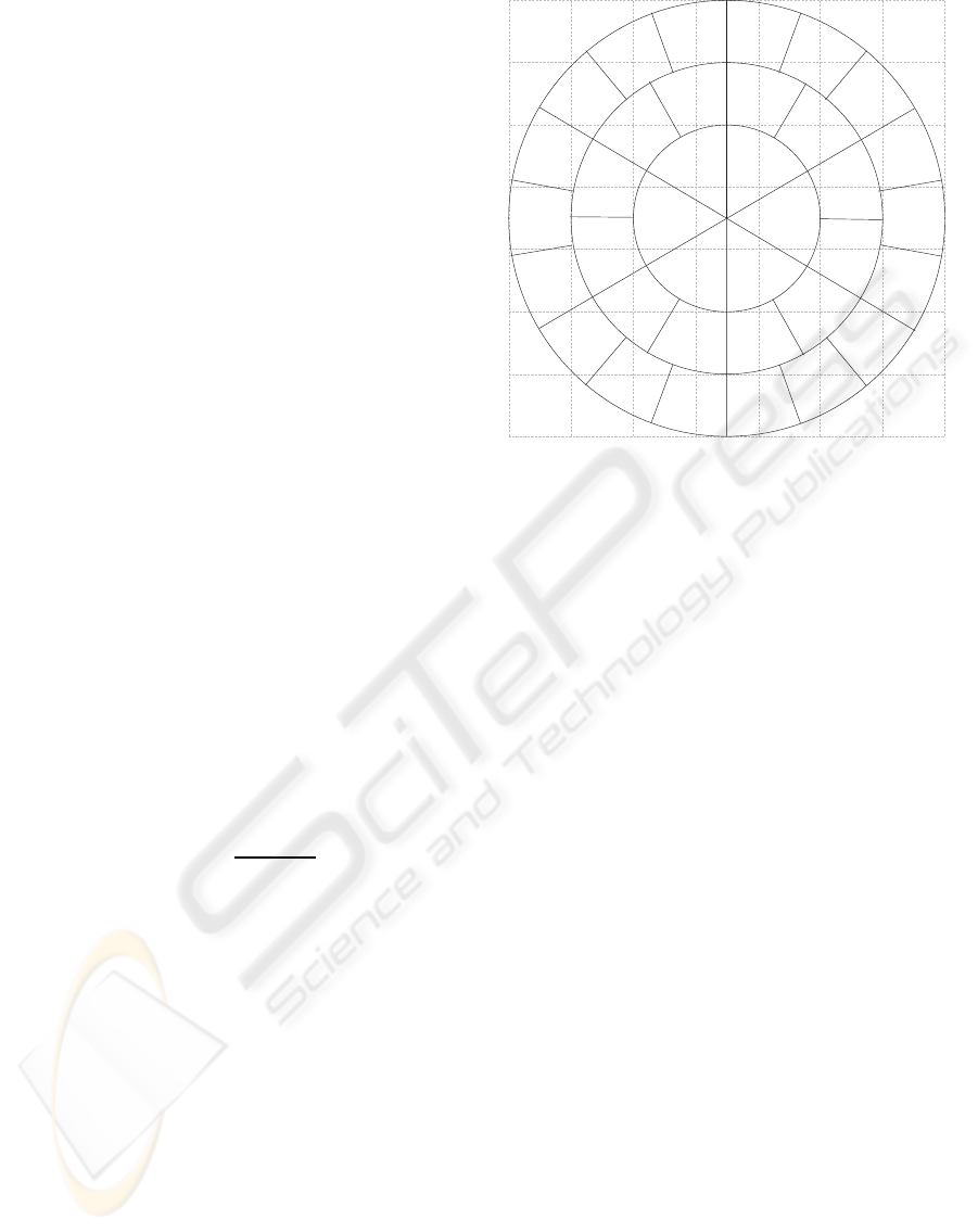
data. Therefore the cylindrical pixels are r wide and
r long. Figure 1 displays the sampling in the simple
case. The maximum r may be also determined in dif-
ferent ways. In this paper, we use r as the half of
the maximum size of the data across all dimensions,
so we make an inner envelope in case the data have
the same size in all dimensions, and therefore we use
something between inner and outer envelope if this
does not apply. In ideal case, the region-of-interest
should be detected and included whole in the cylin-
der. Similar considerations apply also for the height
of the cylinder z (we use 2r
max
).
Corresponding layers from reference and moving
image are registered by PCM which results in a cor-
relation surface that gives a degree of match for each
angle. Correlation surfaces from all layers are then
summed to get the global correlation surface
corr
imp
(α,z) =
S
r
f
∗
R
∑
r=1
rF
−1
L
R
L
∗
M
|L
R
||L
M
|
(α,z) , (6)
where L
R|M
are Fourier transforms of layers l
R|M
.
Each layer is weighted by its radius r which corre-
sponds to the number of pixels it contains. This gives
to each original voxel same impact on the result.
Off-grid image values in equation (5) are com-
puted using linear interpolation. Off-grid layer cor-
relation surface values in equation (6) are computed
using nearest-neighbour interpolation. Finally, posi-
tion of the highest peak in the combined correlation
surface corr
imp
gives the final result of the registration
IRE( f
R
, f
M
) = argmax
α,z
corr
imp
(α,z)
. (7)
We call this algorithm improved rotation estima-
tion and use it in the even iterations of CPCM to esti-
mate the rotation. A comparison with basic version of
the rotation estimation algorithm is shown in experi-
mental part of the paper.
Figure 1: An example of the sampling approach in the im-
proved version of the rotation estimation algorithm. Each
layer of the cylinder is sampled with appropriate resolution.
The first three layers of pixels of improved cylindrical sam-
pling are displayed on top of regular orthogonal pixel grid.
4 EXPERIMENTAL RESULTS
In this section, we present outputs of some exper-
iments that have been done to examine the perfor-
mance of the CPCM method. First, the results of the
whole method are reviewed, as they were published in
(Bican and Flusser, 2007). Second, the improved ver-
sion of the rotation estimation algorithm is examined
and compared with the basic version.
In the experiments and results below, the sizes
and distances are presented in millimetres as the usual
medical volumetric data have different spacing (sam-
pling, voxel size) in each dimension. To relate the
presented distances with the voxel grid, see the cap-
tion of the appropriate figure presenting the data.
4.1 3D Rigid Registration Performance
In the first experiment, whole CPCM method in-
cluding the improvement is examined. We use the
method to register randomly rotated and shifted real
MRI brain image (volume size is 128×128× 40 with
1.8× 1.8× 4.58 mm spacing) with the original. The
degree of misregistration as well as the registration
error is measured by a fixed set of eight points that
uniformly sample the reference image’s volume. The
error (or misregistration) is then measured as a mean
Euclidean distance of these points in moving image
to their original counterparts in reference image. This
VISAPP 2009 - International Conference on Computer Vision Theory and Applications
256
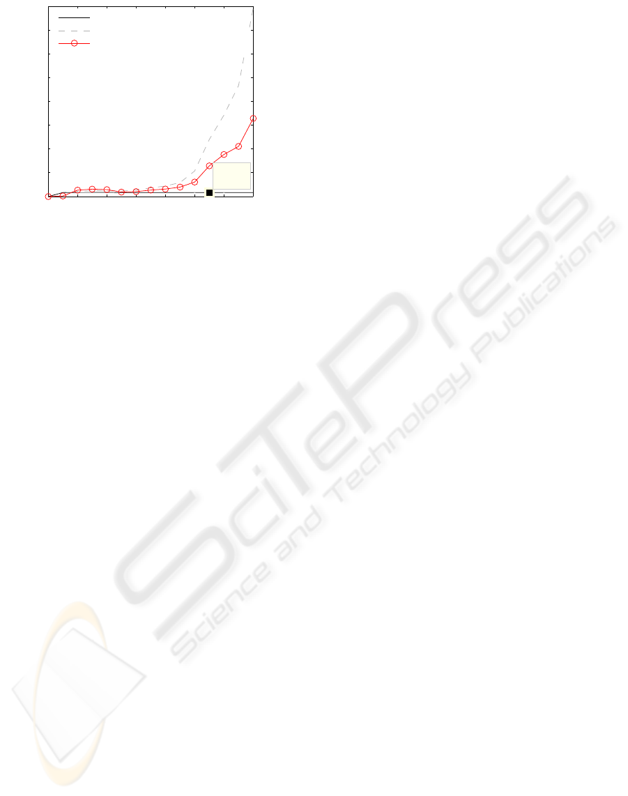
0 20 40 60 80 100 120 140
0
10
20
30
40
50
60
70
80
Mean Error [mm] / No. of iterations
X: 110
Y: 1.685
Registration result (error<=10mm)
Registration result (with errors)
Wrong results (error>10mm)
Figure 2: Influence of initial misregistration on the mean
error after registration in successful registration cases and
cases where the registration did not decrease the error under
10 mm level. Percentage of these failure cases is shown by
the third series.
could be understood as a mean distance of every point
of a volume to its transformed counterpart.
We continuously generated random transforms, so
that there was at least one hundred of different trans-
forms for each 1 mm level of initial misregistration.
For each misregistration level, the results are the mean
values over all transforms that introduced misregistra-
tion of that level. The graph in Fig. 2 shows two al-
ternative views of the results. First, we filtered only
those results that successfully converged under some
reasonable error (here 10 mm – explained below).
Then the graph also plots values that include all re-
sults. The figure also shows the statistics of failures,
i.e. the percentage of cases when the method was not
able to decrease under the error level 10 mm. The
failure happens due to the local solution found during
the optimization or due to the maximum number of
iterations reached (the limit was 120 iterations).
The results can be interpreted such that until the
misregistration is up to about 100 mm, the method
converges to the pixel level precision with at least
90% reliability. As misregistration grows over 100
mm (which is approximately the radius of the vol-
ume), the failure rate increases and method’s perfor-
mance decreases mainly due to cases in which method
converged to some false position. We should point out
that these results and trends do not depend on the spe-
cific value of reasonable error mentioned above. We
use value of 10 mm that is one order higher than the
pixel size and is still reasonable small, but we could
use values 5-45 mm without any significant effect on
the graph.
4.2 Influence of Noise and Rotation Axis
Error on Rotation Estimation
Algorithms for estimation of rotation angle (basic and
improved version described above) were tested for ro-
bustness under non-ideal conditions. First, we want
to examine the influence of these conditions on algo-
rithm’s behaviour and second, we want to justify the
improvement.
In the first part of this experiment, a simulated
MRI brain image (BrainWeb (Collins et al., 1998)
simulated MRI brain image — volume size is 181 ×
217 × 180 with regular 1 mm spacing in all dimen-
sions) was rotated around fixed axis by random an-
gle and Gaussian noise was added to the rotated im-
age. The rotation angle was then recovered by both
basic and improved version of the algorithm and an
absolute difference of estimated and original angle
was measured as an estimation error. We generated
many random angles for each level of noise with a
new instance of noise for each measurement. Graph
3a shows averaged errors over all measurements for
each level of noise.
The second part of this experiment was similar but
instead of adding noise we shifted rotation axis in a
random direction. Hence the algorithms were estimat-
ing rotation around different axis than the image was
originally rotated (note that these algorithms may not
recover original rotation axis). Graph 3b shows de-
pendency of rotation angle error on the distance of
the axis shift (again, error was averaged over many
measurements for each shift distance).
Algorithms proved extreme robustness to noise.
This can be explained due to averaging nature of
PCM: we look for a single peak (ideally delta-
function) in a correlation surface which is result of
an inverse DFT of frequency spectra combined from
the two images. The single peak is kind-of-average
(linear combination) of all frequency samples that are
affected by the same noise as spatial samples of orig-
inal images. The variance of noise is reduced by av-
eraging, hence thanks to large number of samples of
3D volume is the error of estimated rotation angle low
even for really extreme noise.
If the rotation axis is shifted during rotation esti-
mation, the algorithms were able to recover the angle
as long as some structures in the data match. In both
parts of the experiment, it is clearly observable pos-
itive effect of the improvements given in section 3.
The effect of noise is reduced as well as the effect
of disturbances between the two images (shifting the
axis affects mainly the area near rotation axis which
causes most problems in basic version of the algo-
rithm).
3D PHASE CORRELATION USING NON-UNIFORM CYLINDRICAL SAMPLING
257
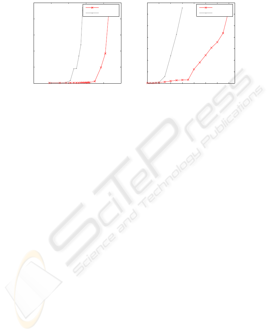
(a) (b)
−45−40−35−30−25−20
0
10
20
30
40
50
Mean Error [Deg]
SNR
Improved
Basic
0 2 4 6 8 10 12 14
0
10
20
30
40
50
60
70
Mean Error [Deg]
Axis shift distance [mm]
Improved
Basic
Figure 3: Influence of noise (a) and axis error (b) on rotation estimation.
5 CONCLUSIONS
We presented an image registration algorithm that is
able to geometrically align mutually translated and ro-
tated pair of 3D images. The method iteratively re-
covers translational component of misalignment by
PCM and rotational component of misalignment by
applying PCM on cylindrically mapped images. The
improvement was given to the rotation estimation step
to reduce the effect of noise and other image distur-
bances.
The experimental results show that the method is
highly resistant to noise and image disturbances. This
resistance is based on the presented improvement to
the rotation estimation step.
Further improvements would focus on the preci-
sion of the method as the actual CPCM is able to reg-
ister only with the pixel-level precision. We are also
going to examine the multi-modal registration poten-
tial as the correlation of whitened images correlates
mainly the image edges and therefore should be able
to register images with common edges but different
intensity levels.
ACKNOWLEDGEMENTS
The authors would like to thank to Czech Min-
istry of Education for support under the project No.
1M6798555601 (Research Center DAR) and to the
Charles University in Prague for support under the
project GAUK 48908 (Medical Image Registration
and Fusion).
REFERENCES
Baker, M. (1998-2007). www.euclideanspace.com: Maths
- rotations.
Bican, J. and Flusser, J. (2007). Cylindrical phase correla-
tion method. In Kropatsch, W. G., Kampel, M., and
Hanbury, A., editors, Computer Analysis of Images
and Patterns, 12th International Conference, CAIP
2007, Vienna, Austria, August 27-29, 2007, Proceed-
ings, volume 4673 of Lecture Notes in Computer Sci-
ence, pages 751–758. Springer.
Collins, D. L., Zijdenbos, A. P., Kollokian, V., Sled, J. G.,
Kabani, N. J., Holmes, C. J., and Evans, A. C. (1998).
Design and construction of a realistic digital brain
phantom. IEEE Trans Med Imaging, 17(3):463–468.
De Castro, E. and Morandi, C. (1987). Registration of trans-
lated and rotated images using finite Fourier trans-
form. IEEE Trans. Pattern Analysis and Machine In-
telligence, 9(5):700–703.
Keller, Y., Shkolnisky, Y., and Averbuch, A. (2006). Volume
registration using the 3-D pseudopolar Fourier trans-
form. IEEE Trans. Image Processing, 54(11):4323–
4331.
Kuglin, C. and Hines, D. (1975). The phase correlation
image alignment method. In Proc. Int. Conf. on Cy-
bernetics and Society, pages 163–165. IEEE.
Press, W., Flannery, B., Teukolsky, S., and Vetterling, W.
(1992). Numerical Recipes in C. Cambridge Univer-
sity Press, second edition.
Reddy, B. and Chatterji, B. (1996). An fft-based technique
for translation, rotation, and scale-invariant image reg-
istration. IEEE Trans. Image Processing, 5(8):1266–
1271.
Zitov´a, B. and Flusser, J. (2003). Image registration
methods: a survey. Image and Vision Computing,
21(11):977–1000.
VISAPP 2009 - International Conference on Computer Vision Theory and Applications
258
