
A LOW-COST EEG STAND-ALONE DEVICE FOR BRAIN
COMPUTER INTERFACE
Alexandre Ribeiro†, Ant
´
onio Sirgado†, Jo
˜
ao Aperta†, Ana Lopes†‡
Jorge Guilherme†, Pedro Correia†, Gabriel Pires†‡ and Urbano Nunes‡
†Department of Electrical Engineering, Polytechnic Institute of Tomar, Tomar, Portugal
‡Institute for Systems and Robotics, University of Coimbra, Coimbra, Portugal
Keywords:
EEG, Stand-alone device, BCI, SSVEP.
Abstract:
This paper describes the ongoing development and design of a portable and stand-alone EEG device to be
used as a Brain Computer Interface (BCI) for wheelchair steering. The overall system comprises the EEG
(electroencephalogram) amplifier, data acquisition, communications and stimuli generator. The main attrac-
tive feature of this system is its stand-alone operation which makes it independent of a computer for signal
processing and visual stimuli presentation. Preliminary results obtained from experiments exploring alpha
rhythms and steady state visual evoked potentials attest the overall functionality and robustness of the system.
1 INTRODUCTION
EEG portable devices are mainly used for long term
signal recording or for remote real-time monitoring
(Jiang and Wang, 2005). They are usually small sized
and low-cost and therefore suitable for a daily using.
EEG-based BCI systems are however almost always
dependent of a personal computer (PC) and its screen.
This is mostly because they rely on real-time heavy
processing algorithms and because a computer screen
is needed to provide visual feedback information or
visual stimuli presentation.
Current main non-invasive BCI systems based on
EEG data are divided in three main classes according
to the type of neuromechanisms: event related syn-
chronization and desynchronization (ERD/ERS) of µ
and β rhythms usually associated with motor imagery
(Pfurtscheller et al., 1998), P300 evoked potentials
(Donchin et al., 2000), and finally, steady-state visual
evoked potentials (SSVEP) (Gao et al., 2003). The
first approach is usually used for 1D or 2D cursor con-
trol on a computer screen to select targets or letters (as
a spelling device), or for playing simple games. The
large number of required EEG channels and the heavy
processing needed for EEG pre-processing, feature
extraction and classification make this BCI approach
highly dependent on a computer system. The visual
P300-based BCI approach depends on the user at-
tentional focus to an infrequent specific visual stim-
ulus that occurs among other random stimuli (Pires
et al., 2008). The stimuli can be generated with
LEDs or with a low cost display controlled by a mi-
crocontroller, without resorting to a computer and
screen. Assuming that many EEG epochs are aver-
aged, then low computational demanding feature ex-
traction techniques can be implemented on a micro-
controller or DSP. However, the use of a large number
of epochs slows down the BCI transfer rate and it re-
quires a buffer of several seconds. In the last BCI ap-
proach, the SSVEP results from a stimulus flickering
at a constant frequency. The flicker stimuli are eas-
ily implemented with some LEDs, and signal feature
extraction and classification can rely essentially on a
FFT (fast fourier transform) that can be computed on
a simple DSP.
Therefore, the SSVEP BCI approach is the only
one that can be easily implemented on a stand-alone
device. Some works have already been developed fol-
lowing a similar approach. The work presented in
(Gao et al., 2003) describes a stand-alone device DSP-
based. A 48 LED stimuli generator is used to control
external devices (TV, videos, etc.) through the clas-
sification of SSVEP signals recorded at the occipital
brain region. The LEDs are flickering at frequencies
between 6 and 15 Hz with a 0.2 Hz resolution.
The use of a stand-alone device is of particular
importance for us since it is intended to be applied
as a BCI to steer a wheelchair (Pires and Nunes,
430
Ribeiro A., Sirgado A., Aperta J., Lopes A., Guilherme J., Correia P., Pires G. and Nunes U. (2009).
A LOW-COST EEG STAND-ALONE DEVICE FOR BRAIN COMPUTER INTERFACE.
In Proceedings of the International Conference on Biomedical Electronics and Devices, pages 430-433
DOI: 10.5220/0001780304300433
Copyright
c
SciTePress
2002). Therefore, computer independence, portabil-
ity and low power consumption are required criteria.
BCIs based on SSVEP are not considered true BCIs
because the users have to gaze the specific stimulus
and therefore have to move the eyes. Notwithstanding
this, the interface can be suitable for people with se-
vere motor disabilities and unable to control standard
interfaces such as joysticks, head switches, voice or
eye trackers, but still able to perform small eye move-
ments.
The remaining sections of the paper describe the
design and implementation of the system still under
development, and also some preliminary results al-
ready reached.
2 MODULE ARCHITECTURE
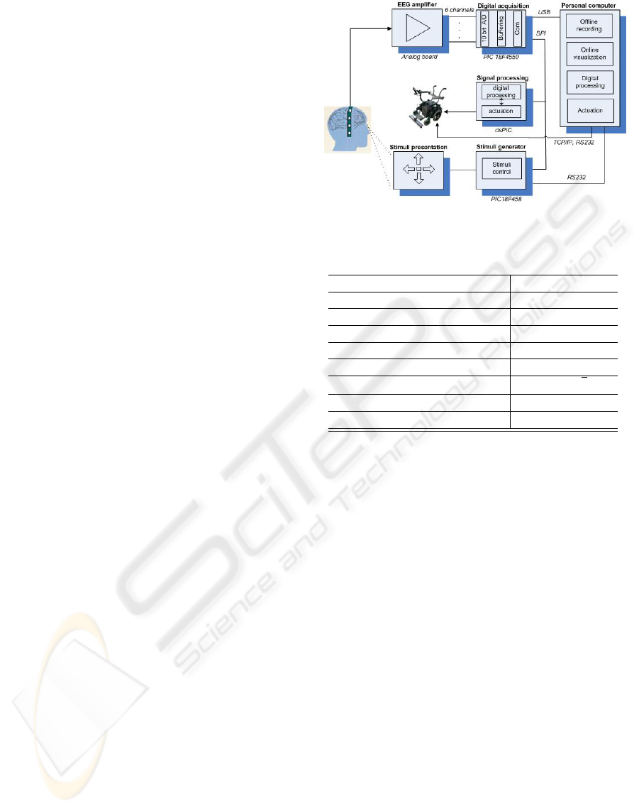
The diagram on Figure 1 illustrates the proposed ar-
chitecture. The first module is a 6 channel EEG
amplifier that receives EEG signal picked from non-
invasive electrodes. The output signal is in the range
of 0 − 5V. The data acquisition module is a PIC
18F4550 (Microchip, 2008), which was configured to
sample the signal at a 512 Hz rate and was imple-
mented based on a real-time interrupt. The A/D con-
verter has a 10 bit resolution. The digital signal is
then sent via USB to a PC for data recording, mon-
itoring or real-time signal processing. If working on
stand-alone mode, digital data is sent via SPI to the
dsPIC 30F3013. The dsPIC is able to perform some
statistical computation, digital filtering and FFT com-
putation to extract signal features for classification.
The output from decoded patterns can be directly sent
to a control unit on the wheelchair. The last module is
a stimuli generator implemented on the PIC 18F458.
It controls a set of LEDs that can be activated sequen-
tially, randomly, or at a given frequency (Figure 5).
The module is therefore suitable to generate stimuli
for SSVEP and for P300. In the case of P300 opera-
tion, each stimulus code is sent to the dsPIC via SPI or
to the PC via USB or RS232. Table 1 presents some
of the main specifications of the system.
On the present development stage, only one am-
plifier channel was implemented. The signal process-
ing algorithms are not running at the dsPIC, but only
at the PC after signal recording.
2.1 Amplifier
EEG signals are characterized by having very low am-
plitude values, typically in the range of 5-100 µV, re-
quiring a very accurate conditioning in order to am-
plify input signals and reject the existing noise or in-
Figure 1: System architecture.
Table 1: Overall system specifications.
Number of channels 6
Resolution 10 bit
Min input voltage step detect 195nV
Input voltage full scale 200 µV
Input frequency range 0.25-45 Hz
CMRR 100-120 dB
Noise spectral density 339 nV/
p
(Hz)
Min and Max Gain 66-91 dB
Current per channel 6 mA
terferences. A high input impedance of the condition-
ing module avoid signal distortion due to loading ef-
fects.
An EEG amplifier module was developed for
signal conditioning and amplification. The mod-
ule design follows the OpenEEG project approach
(OpenEEG-Project, 2008). The main difference was
the insertion of a notch filter to reject the 50 Hz from
power line interference. This improvement made pos-
sible the use of standard electrodes, whilst the Ope-
nEEG project needs non-standard shielded electrodes.
The amplifier module is shown in Figure 2.
The EEG signals acquired from the electrodes pass
through the protection circuit who acts as a voltage
and current limiter. The instrumentation amplifier
with 28dB of gain is implemented with the INA128P
circuit that is characterized by having low offset volt-
age, typically 50 µV, and high Common Mode Re-
jection Ratio (CMRR) (between 100-120 dB). One
second-order high-pass filter with cut-off frequency
at 0.16 Hz and gain 15 to 40dB follows the INA128P
in order to increase the input signal amplitude and
to reject the DC component imposed by the ampli-
fier offset voltage. Then, the signal passes through
an anti-aliasing filter that is a third-order Bessel low-
pass filter with cut-off frequency of 45Hz and gain
22.4dB. In order to reject the 50Hz component, the
A LOW-COST EEG STAND-ALONE DEVICE FOR BRAIN COMPUTER INTERFACE
431
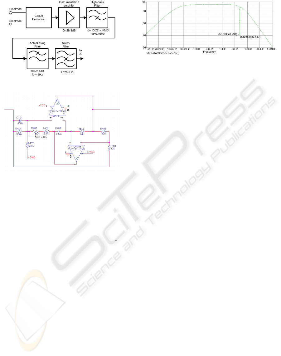
Figure 2: Block diagram of EEG Amplifier.
Figure 3: Notch filter circuit.
EEG amplifier stage includes one notch filter imple-
mented using the GIC (Generalized Immittance Con-
verter) topology with adjustable central frequency, f
0
,
varying between 44Hz and 58Hz and 50dB of atten-
uation at f
0
. The notch filter circuit implementation
and EEG amplifier frequency response simulation are
shown in Figures 3 and 4. The signal conditioning
system has a noise spectral density of 339nV/
p
(Hz),
which achieves a signal-to-noise ratio higher than the
maximum required by the A/D converter of 61.96 dB
for a N = 10 bit converter (Eq. 1).
SNR = 6.02N + 1.76dB (1)
The circuit dynamic range has to take into account the
signal dynamics of a crest factor of about 6dB plus
the required SNR of the ADC. Therefore the required
circuit minimum dynamic range is 67.96dB. The cir-
cuit SNR, considering a noise bandwidth of 256 Hz is
about 120dB which is more than enough for the appli-
cation. The sampling frequency of the ADC was set
to 512Hz that is a decade above the aliasing filter cut
off frequency. The filter attenuation at half the sam-
pling frequency is not critical since the type of signal
detected by the sensor do not fall in this frequency
zone.
Figure 4: Amplifier gain obtained from PSPICE simulation.
3 EXPERIMENTS AND RESULTS
Two experiments were performed with two subjects
to evaluate the performance of the system. The EEG
activity was recorded from Ag/Cl electrodes at posi-
tion Oz according to the internacional 10-20 standard
system (Figure 5). The electrode was referenced to
the right mastoid and the ground was placed at AFz.
The cap and electrodes are g.tec products.
The first experiment consisted on the analysis of
the alpha rhythms (typically in the range 8-12 Hz).
It is known that there is an increase of the amplitude
of alpha rhythms when the eyes are closed and a de-
crease when the eyes are open (Feige et al., 2005).
Figure 6 (top) presents the recorded signal, bandpass
filtered between 8 and 12 Hz, during the two situ-
ations. It was asked the user to be relaxed and to
close the eyes and open them (without any kind of vi-
sual stimuli in front) alternately during some seconds.
During the open-eyes period there is a clear decrease
of alpha amplitude, and an increase during the closed-
eyes period. In Figure 6 (bottom), the FFT of the non-
filtered recorded signal shows a peak at the 10 Hz
when the eyes are closed. To compare and evaluate
the results, similar experiments were performed with
a certified commercial amplifier, reaching the same
results.
The second experiment was performed to validate
simultaneously the stimuli generator and the SSVEP
BCI approach. The user was asked to gaze alternately
two LEDs stimuli blinking at frequencies 15 Hz and
16 Hz. Figure 7 shows the SSVEP signals recorded
at Oz channel. The two frequencies were clearly dis-
criminated. The plot correponds to the application of
the FFT to a time window of 1 s (1 Hz resolution).
These results attest the validity of the overall system
and also of the SSVEP BCI approach.
4 CONCLUSIONS
This paper describes the implementation of a low cost
EEG system for BCI. The amplifier, digital data ac-
BIODEVICES 2009 - International Conference on Biomedical Electronics and Devices
432
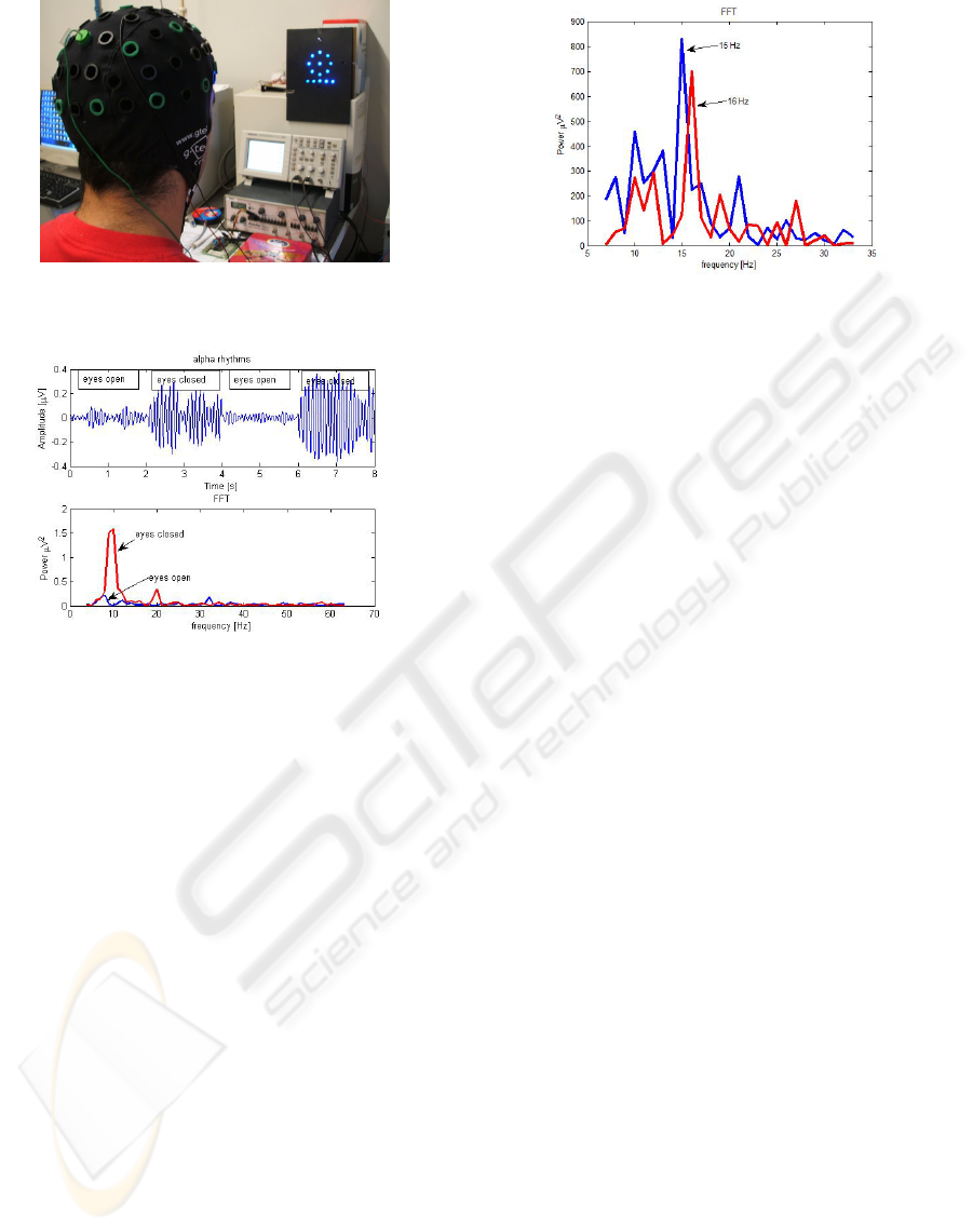
Figure 5: Subject with electrodes cap and stimuli presenta-
tion.
Figure 6: Top) Alpha rhythms recorded with open eyes vs.
close eyes; Bottom) FFT of recorded signal with open eyes
vs. close eyes.
quisition and USB communications were already im-
plemented, tested, and validated. A full stand-alone
operation was already achieved, through the connec-
tion of the dsPIC via SPI, even though signal pro-
cessing algorithms are still in the early steps of de-
velopment. Also, the batteries supply system is cur-
rently under development. The proposed SSVEP BCI
was also tested reaching 15 and 16 Hz discrimination
applying a FFT. For comparing purposes the experi-
ments were also performed with a commercial EEG
system. The results showed a similar performance.
ACKNOWLEDGEMENTS
This work has been in part supported by Fundac¸
˜
ao
para a Ci
ˆ
encia e Tecnologia (FCT), under Grants
POSC/EEASRI/58279/2004 and PTDC/EEA-
ACR/72226/2006.
Figure 7: FFT of the SSVEP signal for a 15 Hz and 16 Hz
stimuli.
REFERENCES
Donchin, E., Spencer, K., and R., W. (2000). The mental
prosthesis: Asensing the speed of a p300-based brain-
computer interface. IEEE Trans. on Rehabilition Eng.,
8(2):174–179.
Feige, B., Scheffler, K., Esposito, F., Salle, F. D., Hennig, J.,
and Seifritz, E. (2005). Cortical and subcortical corre-
lates of electroencephalographic alpha rhythm modu-
lation. Journal of Neurophysiology, 93:2864–2872.
Gao, X., Xu, D., Cheng, M., and Gao, S. (2003). A bci-
based environmental controller for the motion dis-
abled. IEEE transactions on Neural Systems and Re-
habilitation Engineering, 11(2):137–140.
Jiang, X. and Wang, X. (2005). Development of ultra small
two-channel system of eeg radio telemetry. First Int.
Conf. on Neural Interface and Control, pages 60–63.
Microchip (2008). http://www.microchip.com/.
OpenEEG-Project (2008). http://openeeg.sourceforge.net/.
Pfurtscheller, G., Christa, N., Scholgl, A., and Lugger, K.
(1998). Separability of eeg signals recorded during
right and left motor imagery using adaptive autore-
gressive parameters. IEEE Trans. on Rehab. Engineer-
ing, 6(3):316–324.
Pires, G. and Nunes, U. (2002). A wheelchair steered
through voice commands and assisted by a reactive
fuzzy logic controller. Journal of Intelligent and
Robotic Systems, 34(3):301–314.
Pires, G., Nunes, U., and Castelo-Branco, M. (2008). Use of
a P300-based BCI to Steer a Wheelchair: a Bayesian
Approach. In 30th Annual Int. Conf. of the IEEE Engi-
neering in Medicine and Biology Society - EMBC08,
pages 658–661.
A LOW-COST EEG STAND-ALONE DEVICE FOR BRAIN COMPUTER INTERFACE
433
