
SIMPLE FLEXIBLE SKINNING
BASED ON MANIFOLD MODELING
Franck H
´
etroy
1,2
, C
´
edric G
´
erot
3
, Lin Lu
4
and Boris Thibert
1
1
Universit
´
e de Grenoble & CNRS, Laboratoire Jean Kuntzmann, Grenoble, France
2
INRIA Grenoble - Rh
ˆ
one-Alpes, Grenoble, France
3
Universit
´
e de Grenoble & CNRS, GIPSA-Lab, Grenoble, France
4
Department of Computer Science, The University of Hong Kong, Hong Kong, China
Keywords:
Skinning, Manifold atlas, Covering.
Abstract:
In this paper we propose a simple framework to compute flexible skinning weights, which allows the creation
from quasi-rigid to soft deformations. We decompose the input mesh into a set of overlapping regions, in a
way similar to the constructive manifold approach. Regions are associated to skeleton bones, and overlaps
contain vertices influenced by several bones. A smooth transition function is then defined on overlaps, and is
used to compute skinning weights. The size of overlaps can be tuned by the user, enabling an easy control of
the desired type of deformations.
1 INTRODUCTION
Skeletal animation is a widespread technique to
deform articulated shapes. It uses a joint hierarchy
called skeleton; during the animation, joints are
translated and/or rotated then each vertex of the
shape (usually represented by a mesh) is deformed
with respect to the closest joints. The process that
describes the skin deformation is called skinning.
Many skinning techniques attach joint (or bone)
weights to each vertex of the mesh; a weight specifies
the amount of influence of the corresponding joint on
the vertex. Defining proper values for joint weights
is often time-consuming for the animator. Usually,
weights are defined using the Euclidean distance
between the vertices and the joints. A basic painting
tool (or equivalent) can be applied manually to
quantify which vertices are influenced by a given
joint. Careful manual tuning is then required to set
up weights that give the desired deformation.
In this paper, we propose a simple framework to
automatically compute skinning weights, with a
user control on the type of deformation. We get
inspiration from the concept of constructive manifold
atlas (Grimm and Zorin, 2005). Contrary to piece-
wise modeling, an atlas allows to construct a surface
from pieces of surface which overlap substantially
instead of abutting only along their boundaries. As a
consequence, when one piece is stretched or moved,
the overlapping pieces follow this deformation or
motion. We use this idea to compute skinning weights
for any shape, proceeding in two steps. Firstly, a
covering of the mesh, with regions associated to
skeleton bones, is defined (Section 3). This covering
can be controlled on the overlapping areas. Secondly,
a partition of the unity is defined on this covering for
each vertex of the mesh, providing the weights for
the skinning (Section 4).
Our weight computation scheme is both simple and
fast. Control is easy since only one parameter has to
be tuned in order to move from a quasi-rigid defor-
mation to a soft one, and no manually tuned example
nor additional tool is required as input. We demon-
strate the effectiveness of our framework on a set of
examples (Section 5).
2 RELATED WORK
2.1 Flexible Skinning
Most skinning weight computation methods try
to generate ideal weights for realistic character
animation. They can rely on geometric features,
such as the medial axis of the object (Bloomenthal,
259
Hétroy F., Gérot C., Lu L. and Thibert B. (2009).
SIMPLE FLEXIBLE SKINNING BASED ON MANIFOLD MODELING.
In Proceedings of the Fourth International Conference on Computer Graphics Theory and Applications, pages 259-265
DOI: 10.5220/0001767602590265
Copyright
c
SciTePress
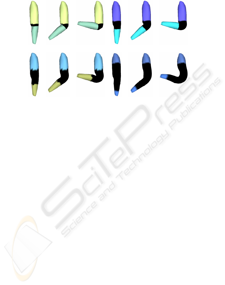
(a) (b)
(c) (d)
Figure 1: Rest pose, medium deformation and large deformation around an elbow. K = 0.1, 0.5,1.0 and 2.0 for (a), (b), (c)
and (d) respectively. Overlap areas are shown in black. Overlaps and weights were computed using a geodesic distance, and
deformations were created using the technique of (Kavan et al., 2007).
2002) or a mesh segmentation (Katz and Tal, 2003;
Attene et al., 2006), or on example poses (e.g. (Merry
et al., 2006; Wang et al., 2007; Weber et al., 2007)).
An increasingly popular solution is to solve a heat
equation for each joint in order to automatically
set the weights associated to this joint (Baran and
Popovi
´
c, 2007; Weber et al., 2007). However, these
solutions usually do not allow for flexible skinning.
To the best of our knowledge, only a few skinning
methods allow different kinds of deformations. One
of them is to use spline-aligned deformations instead
of the traditional Linear Blend Skinning (LBS),
which can be mixed with user-designed deformation
styles (Forstmann et al., 2007). Another solution is to
compute the set of possible new locations for a vertex
deformed with LBS and let the user choose the one
he wants (Mohr et al., 2003). Recently, Rohmer et
al. proposed a local volume preservation technique
which enables the creation of both rubber-like and
realistic deformations for organic shapes, depending
on the correction map applied to skinning weights
(Rohmer et al., 2008). The solution we suggest is
more flexible in the sense that any deformation, from
quasi-rigid to soft, can be created, and any skinning
method can be used: for instance LBS, (Merry et al.,
2006; Kavan et al., 2007). It also lies in the general
(rigid) skeleton-based animation framework, and do
not need the creation of new tools such as spline
curves.
Our method can be related to the “mesh forging”
approach of Bendels and Klein (Bendels and Klein,
2003), except that we propose a Hermite function as a
transition function between two bones, while they let
the user draw the function.
2.2 Modeling with an Atlas
Surface modeling with an atlas has properties which
lends itself to the skinning problem. Indeed construc-
tive manifold definitions (Grimm and Zorin, 2005)
represent a surface as a set of blended embedded
planar disks. The blending is performed as a convex
combination whose weights are defined as a partition
of the unity overall the planar disks. Hence the
surface is made up with 3D regions which overlap
substantially and are glued together. As a conse-
quence, when an embedded planar disk is stretched
or moved, the overlapping regions are stretched or
moved accordingly. Defining such a set of regions
per joint of the skeleton provides a skinning.
However, this construction makes sense only if
the planar disks are linked together with transition
functions. These functions indicate which embedded
points have to be combined together in the blending
process. To do so, either a proto-manifold associated
with a mesh with a large number of pieces (at least
one per vertex) is defined (Grimm and Hughes, 1995;
Navau and Garcia, 2000; Ying and Zorin, 2004),
or a pre-defined manifold with a small number of
pieces, but in general not adapted to the particular
geometry to be represented is used (Grimm, 2004).
GRAPP 2009 - International Conference on Computer Graphics Theory and Applications
260
These constructions target a global highly-continuous
parameterization of the surface. This implies major
contraints on the definition of the transition functions.
Reversely, an atlas can be constructed from the final
surface to be represented. The global parameteriza-
tion of the surface is used for high-quality sampling,
texture mapping or reparameterization (Praun et al.,
2000). In this case again, the components of the
atlas have to be defined explicitly and with continuity
constraints.
Real-time constraints impose to deal with small struc-
tures and to consider meshes as C
0
-surfaces. Hence,
we propose to adapt this parameterization-oriented
framework onto a lighter one, sufficient for skinning
and providing a better control on the overlapping in-
fluences of different skeleton bones than other skin-
ning algorithms.
3 C
0
ATLAS DEFINITION
Our work takes as input a closed mesh and an em-
bedded animation skeleton. As stated in Section 2.2,
we adapt the manifold modeling with an atlas onto
a lighter framework sufficient for skinning. Follow-
ing constructive manifold approach, we decompose
the mesh into overlapping regions. Despite the fact
that these regions are not necessarily homeomorphic
to discs, they will be interpreted as charts with transi-
tion functions implicitely defined by the shared faces.
In order to control these overlapping areas, we first
segment the mesh into a partition of regions associ-
ated to skeleton bones, and then stretch these regions
onto a covering of the mesh. Note that regions are
not restricted to cylindrical shapes with at most two
boundaries.
3.1 Initial Mesh Segmentation
To decompose the mesh into overlapping regions, we
need as a preprocess its segmentation into regions
associated to skeleton bones. Any skeleton-based
segmentation method can be used, such as for
instance (Katz and Tal, 2003; de Goes et al., 2008)
which also use segmentation to create animations. In
our implementation, we use a simple yet robust au-
tomatic mesh segmentation algorithm. Our approach
is to first find the boundaries of the regions, which
should be associated to skeleton joints since regions
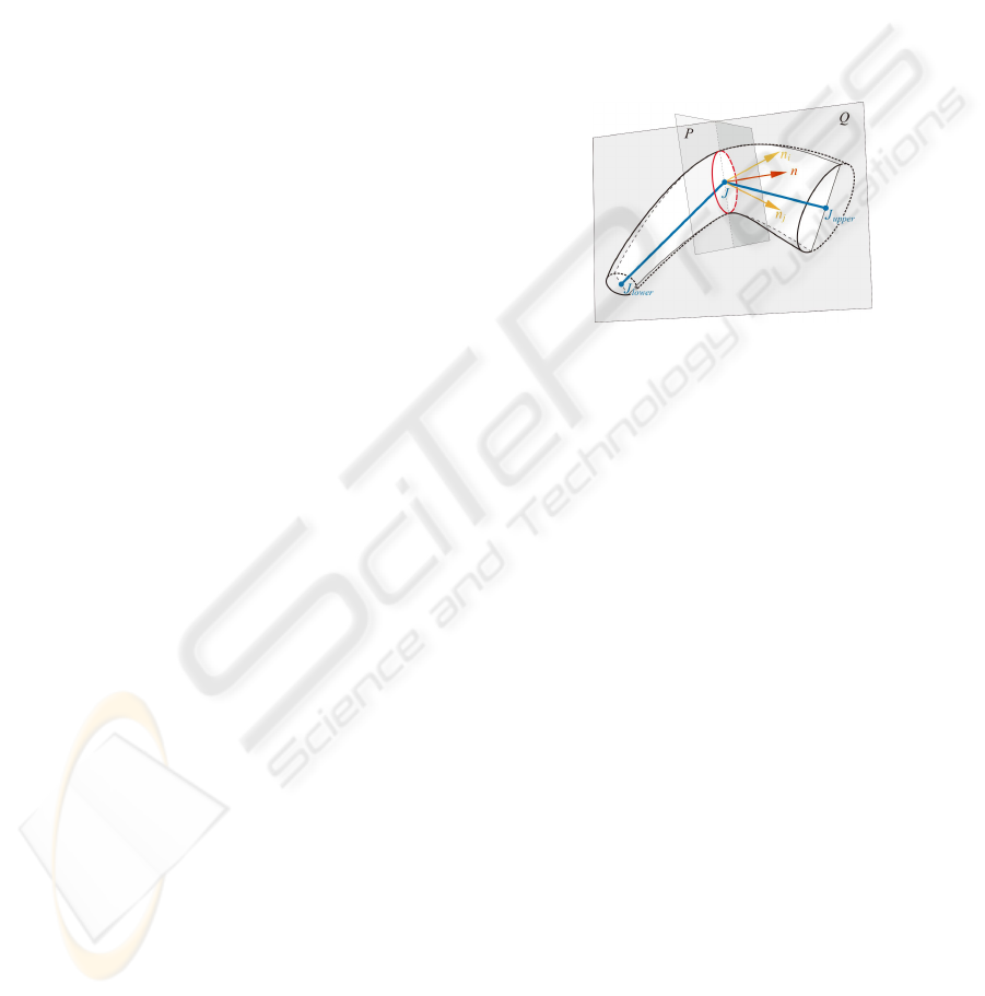
are associated to skeleton bones. The boundary B
associated to joint J is defined as the intersection
between the input mesh and a plane P going through
J and orthogonal to a plane Q (see Figure 2). Q is
defined by the two bones incident to J. In case more
than two bones are incident to J (this is for instance
the case of the pelvis joint for a human model), we
can use the skeleton’s hierarchy to select two of them.
There is an infinite number of possible planes P, but
each one can be defined by its normal n, which lies in
the plane Q. In practice we compute a discrete set of
planes P
0
,...,P
k−1
, by selecting a random n
0
normal
vector and then rotating it around J with an angle
2πi/k, 1 ≤ i < k. Then we keep the plane such that
the length of the corresponding boundary curve B is
minimum.
Figure 2: Each boundary is defined with respect to a plane
P going through a joint J.
Although this method is quite simple, it provides seg-
mentations which are robust to noise on the input
mesh, to the initial pose of the character and to the
location of joints, as can be seen on Figure 3. Once
again, we emphasize that any other skeleton-based
segmentation method can be applied instead of this
one, as a pre-processing step for overlap generation.
3.2 Overlap Generation
We now describe how we generate a mesh decompo-
sition into overlapping pieces from this segmentation.
Suppose that the mesh M is decomposed into r
regions {R
j
}
r
j=1
; we note {B
i
}
b
i=1
the b boundaries
between these regions. Besides, each B
i
has 2 adja-
cent regions denoted by R
i
1
and R
i
2
; each R
j
has m
boundaries, denoted by {B
j,k
}, with ∀ j,k,B
j,k
= B
k, j
.
Generation of overlaps consists in growing each
region R
j
into a new region R
0
j
with a distance
criterion: R
0
j
is connected and R
j
⊂ R
0
j
. This is done
by integrating vertices of neighbouring regions to
R
0
j
. Thus, each boundary B
j,k
of R
j
is modified into
a new boundary B
0
j,k
of R
0
j
, with B
0
j,k
6= B
0
k, j
(the
new boundary of R
0
k
). Vertices between B
0
j,k
and B
0
k, j
are in the overlap area of R
0
j
and R
0
k
. Note that a
whole region R
0
k
may belong to the overlap area of a
SIMPLE FLEXIBLE SKINNING BASED ON MANIFOLD MODELING
261
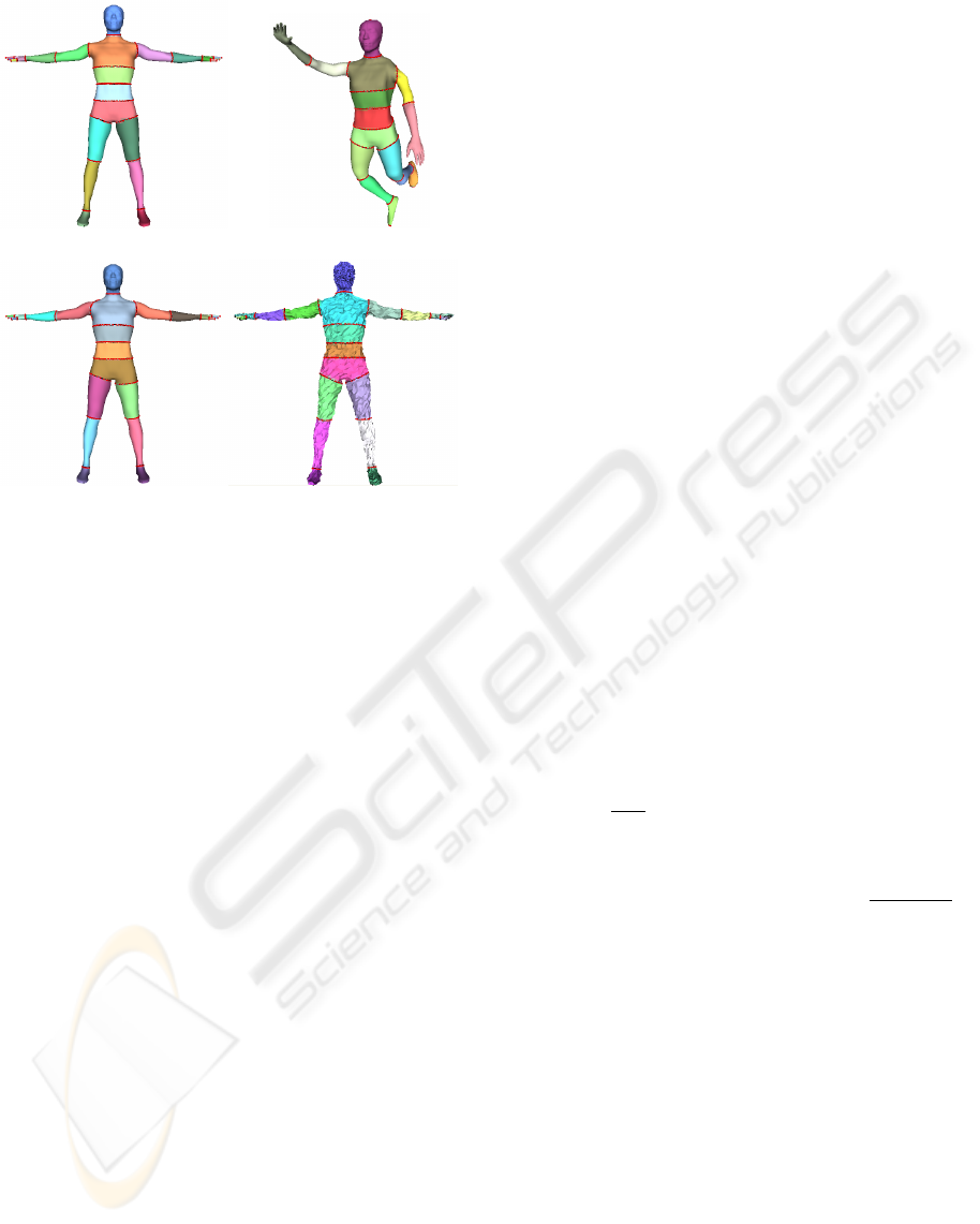
(a) (b)
(c) (d)
Figure 3: Segmentation results for (a) a human model, (b)
the same model with a different pose (and no hand nor arm
joint in the skeleton), (c) the same model with different right
shoulder and left hip joint locations, and (d) the same model
with noised vertex locations.
neighbouring region R
0
j
(see Figure 4).
To compute the overlap areas, we compute for each
vertex v of the mesh its distance to all B
j,k
, and we
let the user choose a size parameter K. Then, we
use the length L
j,k
of B
j,k
as the criterion to generate
the overlap area between R
0
j
and R
0
k
: we mark each
vertex with distance to B
j,k
lower than K ∗ L
j,k
/π
as in this overlap area. (Baran and Popovi
´
c, 2007)
claims that the range of a transition between two
bones (that is to say, the area of the region where
vertices are influenced by both bones) must be
roughly proportional to the distance from the joint to
the surface. This corresponds to K = 0.5.
In our implementation, the same parameter is used
for all areas, but other solutions can be applied: for
instance, K can be chosen according to the type
of skeleton joint, in case semantic information is
attached to joints (Aujay et al., 2007).
Different kinds of distances can be used: Euclidean
distance, approximated geodesic distance or distance
based on a harmonic function, for instance. We tested
several of them and discuss results in Section 5.2.
4 COMPUTATION OF SKINNING
WEIGHTS
In the manifold constructive approach, a partition
of the unity defined on a proto-manifold is used to
blend embedded pieces. In the same way, we define
skinning weights as a partition of the unity on the
covering defined in Section 3.
We define weights that depend on the mesh covering
{R
0
j
}
r
j=1
defined in Section 3.2. In each extended
region R
0
j
a distance map d
j
(v) is specified. It gives
to every vertex v of the region R
0
j
its distance to
the boundary of the region (computed as the lowest
distance from v to all B
0
j,k
). As in Section 3.2, this
can be a Euclidean or geodesic distance, or anything
else. We tested Euclidean, approximated geodesic
and harmonic distances; see Section 5.2 for results
and a discussion.
Let δ
j
be the maximal distance to the boundary in R
0
j
:
δ
j
= max
v∈R
0
j
d
j
(v). Let s(l) be the cubic function
which satisfies the Hermite conditions s(0) = 0,
s(1) = 1, s
0
(0) = s
0
(1) = 0: s(l) = −2l
3
+ 3l
2
. This
cubic function lets us define weights which decrease
smoothly towards 0 as the vertex v is closer to the
region boundary, providing visually better results
(see Section 5.3). However, weights can be defined
with any function such that s(0) = 0 and s(1) = 1.
We define unnormalized weights σ
j
(v) as
σ
j
(v) = s(
d
j
(v)
δ
j
). Let I (v) be the set of
indices of regions the vertex v belongs to
I (v) = { j ∈ {1, . ..,n} : v ∈ R
0
j
}. Normalized
weights ω
j
(v) are then defined as ω
j
(v) =
σ
j
(v)
∑
i∈I (v)
σ
i
(v)
.
Because the regions R
0
j
define a covering of the
surface and s in monotonic from [0, 1] onto [0, 1], the
denominator is never equal to zero and ω
j
(v) ∈ [0,1].
Moreover these well-defined weights define a parti-
tion of the unity associated to this covering: for every
vertex v of the mesh,
∑
j∈I (v)
ω
j
(v) = 1.
Note that for non-overlapped vertices, I (v) is reduced
to a singleton { j} and ω
j
(v) = 1. For a vertex v
belonging to the boundary of a region R
0
j
, we have
d
j
(v) = 0, thus σ
j
(v) = 0 and ω
j
(v) = 0.
GRAPP 2009 - International Conference on Computer Graphics Theory and Applications
262
5 RESULTS AND DISCUSSION
Some deformation results are shown on Figures 1, 4,
6 and 7. In all cases the Dual Quaternion technique
(Kavan et al., 2007) was used to deform the meshes.
The segmentation pre-processing step is done in
real-time, and so is done the weight computation.
Time to compute the overlap areas highly depends
on the chosen distance function: it is almost real
time using a Euclidean distance, but lasts a few
seconds using an approximated geodesic distance, on
a low-end PC.
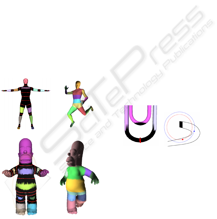
Figure 4 shows the mesh covering defined for two
standard models, and examples of deformations that
can be generated in a few minutes using our frame-
work. K was set to 0.5 (resp. 0.2) for all joints of
the human (resp. Homer) model. Overlaps as well
as skinning weights were computed with an approx-
imated geodesic distance, using Dijkstra’s algorithm
on the mesh’s vertices. As input we only used the
two mesh models and their corresponding animation
skeletons.
(a) (b)
(c) (d)
Figure 4: Computed covering (a,c) and deformation (b,d)
for two models. Overlap areas are shown in black. Note
that some vertices may belong to three or more overlapping
areas, especially around the spine and the pelvis.
5.1 Influence of the Overlap Size
As can be seen on Figure 1, the overlap size K ∗L
j,k
/π
influences the behavior of the deformation around a
joint. For a small value of K, only a few number of
vertices around the joint are smoothly bended out: the
deformation is quasi-rigid. As K becomes larger, the
deformation becomes elastic. Thus tuning K allows
for various kinds of deformations.
5.2 Choice of the Distance Function
As stated in Section 3, several distance functions
can be used to compute both overlap areas and
skinning weights. Using the Euclidean distance
is the simplest and fastest solution. However, in
some cases it generates artefacts (see Figure 5). For
instance, if some part of the input mesh is close to
a joint related to other regions, vertices in this part
can be wrongly set to be in an overlap area of the
joint. This drawback can sometimes be corrected
using the skeleton’s hierarchy, by preventing vertices
from belonging to overlap areas of joints that are
far from their bone in the hierarchy, but this is not
always possible. Euclidean distance can also generate
artefacts for weight computation, in case of curved
regions: see for instance Figure 5 (b).
(a) (b)
Figure 5: Artefacts using the Euclidean distance (overlap
areas are shown in black). (a) For the overlap generation:
an overlap area around a joint can be disconnected. (b) For
the weight computation: the point represented by a square
is closest to the boundary of the region than the point repre-
sented by a triangle.
Figure 6 shows the deformation around a pelvis joint
using Euclidean (first row), approximate geodesic
(second row) or harmonic (third row) distance. Ap-
proximated geodesic distance has been computed
with Dijkstra’s algorithm. Following an idea from
(Aujay et al., 2007), we set two boundary conditions
for the computation of the harmonic distance: the
points on boundary curves have zero distance and the
farthest points to these curves have a distance set to
their approximated geodesic distance to these curves.
SIMPLE FLEXIBLE SKINNING BASED ON MANIFOLD MODELING
263
Although the overlap areas between the three regions
(waist and both thighs) are quite similar, a small arte-
fact can be noticed for the Euclidean distance, due to
the high influence the right thigh has on vertices close
to the left thigh/pelvis boundary.
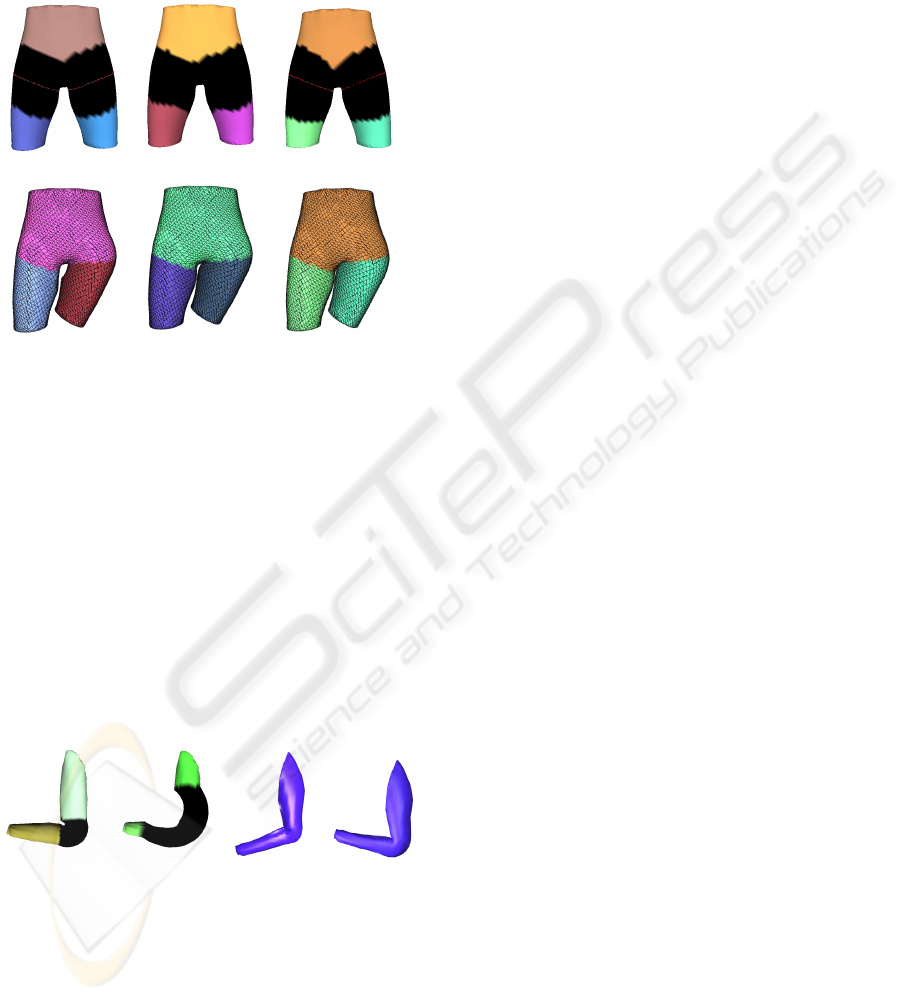
(a) (b) (c)
(d) (e) (f)
Figure 6: Overlap areas (a,b,c) and deformation (d,e,f)
around a pelvis joint using Euclidean (a,d), approximated
geodesic (b,e) and harmonic (c,f) distance. K was set to 0.5
in the first two cases, and to 0.4 in the harmonic case.
5.3 Choice of the Weight Function
Results of deformations using a linear function in-
stead of s to compute the skinning weights are shown
on Figure 7 (a,b). They look much less natural (com-
pare with Figure 1 (b,d)), because of the sharp de-
crease or increase of influence of bones near the over-
lap boundaries. On the contrary, our cubic function s
increases very slowly around l = 0 and l = 1, leading
to visually better results.
(a) (b) (c) (d)
Figure 7: (a,b) Deformations using a linear function in-
stead of a cubic one with K = 0.5 (a) or K = 2 (b). We
used approximate geodesic distance to compute overlap ar-
eas and weights. (c) Deformation using Blender’s paint
tool. (d) Deformation using harmonic weights (Baran and
Popovi
´
c, 2007).
5.4 Comparison with Standard
Methods
Deformations obtained using two standard weight
computation methods and Dual Quaternion technique
are shown on Figure 7 (c,d). Using the paint tool
(available in common software such as Autodesk’s
Maya or Blender), it took approximately half an hour
to get a relatively decent result. The painted area cor-
responds to the overlap area shown on Figure 1 (b).
The use of a harmonic function (Baran and Popovi
´
c,
2007) is as fast as our technique, but do not allow for
accurate control over the size of the deformed region.
6 CONCLUSIONS
We have presented a simple way to compute flexible
skinning weights for skeleton-based animation, based
on the concept of manifold modeling. Starting from
a segmentation of the input mesh into regions corre-
sponding to skeleton bones, we generate overlaps by
extending each region around joints. Size of these
overlaps is controlled by a simple parameter, that can
be user-chosen or automatically computed. Then,
vertices belonging to an overlap area are influenced
by bones related to all regions that overlap. Skinning
weights are defined using a simple smooth function
based on the distance to the overlap boundary.
Results show that this framework allows to create
from quasi-rigid to soft deformations, depending on
the overlap size. Using a geodesic distance instead
of a Euclidean one to create overlaps and compute
skinning weights is more time-consuming, but avoids
some artefacts. We believe our method can be
especially useful for non-expert animators, since it
is simple (only one parameter is to set) and fast to use.
Further work includes anatomic information into the
overlapping width definition. Such information can
be derived from semantic information associated with
skeleton (Aujay et al., 2007). Besides, providing
a skinning framework for multiresolution animated
meshes, founded on our pseudo-parameterization on
the initial mesh, would be a further development in
the similarity with manifold parameterization.
ACKNOWLEDGEMENTS
This work was partially supported by the IMAG,
ELESA and INRIA through the MEGA project and
GRAPP 2009 - International Conference on Computer Graphics Theory and Applications
264

the ANR through the MADRAS project (ANR-07-
MDCO-015). Part of this work was done while Lin
Lu was visiting INRIA with an INRIA Internship
grant.
REFERENCES
Attene, M., Spagnuolo, M., and Falcidieno, B. (2006). Hi-
erarchical mesh segmentation based on fitting primi-
tives. The Visual Computer, 22(3):181–193.
Aujay, G., H
´
etroy, F., Lazarus, F., and Depraz, C. (2007).
Harmonic skeleton for realistic character animation.
In Symposium on Computer Animation, pages 151–
160, San Diego, USA.
Baran, I. and Popovi
´
c, J. (2007). Automatic rigging and ani-
mation of 3d characters. ACM Transactions on Graph-
ics (SIGGRAPH proceedings), 26(3):72.
Bendels, G. and Klein, R. (2003). Mesh forging: Editing
of 3d-meshes using implicitly defined occluders. In
Symposium on Geometry Processing, pages 207–217,
Aachen, Germany.
Bloomenthal, J. (2002). Medial-based vertex deformation.
In Symposium on Computer Animation, pages 147–
151, San Antonio, USA.
de Goes, F., Goldenstein, S., and Velho, L. (2008). A hierar-
chical segmentation of articulated bodies. Computer
Graphics Forum (Symposium on Geometry Process-
ing proceedings), 27(5):1349–1356.
Forstmann, S., Ohya, J., Krohn-Grimberghe, A., and Mc-
Dougall, R. (2007). Deformation styles for spline-
based skeletal animation. In Symposium on Computer
Animation, pages 141–150, San Diego, USA.
Grimm, C. (2004). Parameterization using manifolds. In-
ternational Journal of Shape Modeling, 10(1):51–80.
Grimm, C. and Hughes, J. (1995). Modeling surfaces of
arbitrary topology. In SIGGRAPH, pages 359–367,
Los Angeles, USA.
Grimm, C. and Zorin, D. (2005). Surface modeling and pa-
rameterization with manifolds. In SIGGRAPH Course
Notes, Los Angeles, USA.
Katz, S. and Tal, A. (2003). Hierarchical mesh de-
composition using fuzzy clustering and cuts. ACM
Transactions on Graphics (SIGGRAPH proceedings),
22(3):954–961.
Kavan, L., Collins, S., Zara, J., and O’Sullivan, C. (2007).
Skinning with dual quaternions. In Symposium on In-
teractive 3D Graphics and Games, pages 39–46, Seat-
tle, USA.
Merry, B., Marais, P., and Gain, J. (2006). Animation
space: a truly linear framework for character anima-
tion. ACM Transactions on Graphics, 25(4):1400–
1423.
Mohr, A., Tokheim, L., and Gleicher, M. (2003). Direct
manipulation of interactive character skins. In Sym-
posium on Interactive 3D Graphics and Games, pages
27–30, Monterey, USA.
Navau, J. C. and Garcia, N. P. (2000). Modeling surfaces
from meshes of arbitrary topology. Computer Aided
Geometric Design, 17(1):643–671.
Praun, E., Finkelstein, A., and Hoppe, H. (2000). Lapped
textures. In SIGGRAPH, pages 465–470, New Or-
leans, USA.
Rohmer, D., Hahmann, S., and Cani, M. (2008). Local
volume preservation for skinned characters. Com-
puter Graphics Forum (Pacific Graphics proceed-
ings), 27(7).
Wang, R., Pulli, K., and Popovi
´
c, J. (2007). Real-
time enveloping with rotational regression. ACM
Transactions on Graphics (SIGGRAPH proceedings),
26(3):73.
Weber, O., Sorkine, O., Lipman, Y., and Gotsman, C.
(2007). Context-aware skeletal shape deformation.
Computer Graphics Forum (Eurographics proceed-
ings), 26(3):265–274.
Ying, L. and Zorin, D. (2004). A simple manifold-
based construction of surfaces of arbitrary smooth-
ness. ACM Transactions on Graphics (SIGGRAPH
proceedings), 23(3):271–275.
SIMPLE FLEXIBLE SKINNING BASED ON MANIFOLD MODELING
265
