
A VECTORIZED TRAVERSAL ALGORITHM FOR RAY TRACING
Jos
´
e Mar
´
ıa Noguera
Dept. de Inform
´
atica, Escuela Polit
´
ecnica Superior, University of Ja
´
en, 23071, Ja
´
en, Spain
Carlos Ure
˜
na and Rub
´
en Jes
´
us Garc
´
ıa
Dept. Lenguajes y Sistemas Inform
´
aticos, University of Granada, Granada, Spain
Keywords:
Raytracing, SIMD.
Abstract:
This article presents an optimized ray tracing algorithm which improves standard existing algorithms by pro-
cessing simultaneously a large set of rays and carrying out a single traversal of the spatial indexing of the scene
with all rays. This allows hardware SIMD functionality to be used efficiently and produces coherent memory
accesses. Furthermore, during the single traversal, rays are grouped in such a way that these advantages are
maintained for non coherent ray sets. The algorithm was observed to reduce the computation costs with re-
spect to other standard solutions, especially for non coherent ray sets. It is worth noting that its characteristics
make it especially suitable for graphics hardware.
1 INTRODUCTION
Ray tracing is the dominating technique in the realis-
tic image synthesis field, when the computation time
is a secundary issue. The large processing times are
due to the high computational costs of ray tracing. For
each pixel in the image one or more rays must be sent
through the scene and intersected with the objects it
contains, the colour of the pixel must be calculated,
and finally the pixels must be shown in the screen.
Ray tracing is not only useful in visualization. A
multitude of algorithms, especially in the realistic im-
age synthesis field, are based on ray tracing, such as
photon mapping (Jensen, 1996). Furthermore, these
algorithms usually work with non coherent rays. The
availability of efficient ray tracing algorithms would
allow a substantial decrease in the execution times of
these algorithms. Due to all these reasons, the devel-
opment of new techniques which bring together ray
tracing and real time applications is interesting.
It should be taken into account that using this al-
gorithm for ray tracing or more generally for Global
Illumination, implies that the application must gener-
ate large ray sets in order to calculate their intersec-
tions simultaneously. This means that the algorithm
must be organized in a breadth first scheme (Hanra-
han, 1986); the speedup comes at the cost of increased
memory use. Furthermore, this scheme allows an ef-
ficient vectorized implementation of other parts of the
algorithm.
This article is organized as follows: section 2 pro-
vides a general description of the design ideas of the
algorithm, followed by an in depth description of the
algorithm. Lastly, section 3 offers an efficiency com-
parison to other methods.
1.1 Previous Work
Even though ray tracing is a very old technique (Ap-
pel, 1968), its use for interactive applications is rela-
tively new.
(Wald, 2004; Wald et al., 2001) presents a CPU
based algorithm which exploits the existing coherence
in primary rays. It is based in the idea that coher-
ent rays will very probably make the same traversal
through the spatial indexing structure which contains
the scene, and will intersect the same objects. His
proposal thus consists in traversing the spatial index
and making the ray-triangle intersections with pack-
ets made of four coherent rays at the same time. Using
SIMD instructions of current processors, the compu-
tation time of the algorithm is reduced. In addition,
Wald presents a careful design oriented towards min-
imizing code complexity and cache faults.
58
Noguera J., Ureña C. and Jesús García R. (2009).
A VECTORIZED TRAVERSAL ALGORITHM FOR RAY TRACING.
In Proceedings of the Fourth International Conference on Computer Graphics Theory and Applications, pages 58-63
DOI: 10.5220/0001767500580063
Copyright
c
SciTePress

This idea is valid for primary rays since it is easy
to locate rays which a priori have high probabilities of
coherency. But it fails for secundary rays where this
assumption does not hold. This article presents an ex-
tension to this idea, which permits the parallelization
of calculations for different rays in any situation, even
when these are not coherent. A preliminary version
of this work (in Spanish) can be seen in (Noguera and
Ure
˜
na, 2007).
Recently (Wald et al., 2007) have begun the de-
sign of stream and filter based raytracers. Rays are
processed into a series of streams, and the operations
on the rays are modelled as filters. After the filters,
rays to be processed further are compressed into an-
other stream. The filters can process the rays in paral-
lel using SIMD instructions.
A modelling software has been used to test the
SIMD efficiency of this design for different SIMD
widths (4 to 16), and for different sizes of the ray
packets (2x2 to 64x64), for 1k rays. The efficiency for
large SIMD width decreases noticeably, but still ob-
tains higher efficency than previous approaches due
to the compacting. However, no ray tracer has been
implemented to test the results in real hardware. Our
approach, on the other hand, should not be negatively
affected by large SIMD widths. (Gribble and Ramani,
2008) simulates an approach similar to ours including
larger SIMD width, and report good scalability.
Another approach (Boulos et al., 2008) reorders
and compacts rays only when SIMD efficiency is less
than 50 %, missing some of the ray coherence. Out
of core extensions (Pharr et al., 1997) and low mem-
ory data structures (Mahovsky and Wyvill, 2006) have
also been published.
There have been different attempts to use GPU
processors for ray tracing acceleration (Carr et al.,
2002; Purcell et al., 2002; Foley and Sugerman, 2005;
Christen, 2005). Our approach is suitable for GPU
porting as well.
2 IMPLEMENTATION
The following sections describe our ray tracer imple-
mentation. Firstly a general description of the design
ideas used is shown, and their application to the algo-
rithm. The following sections describe the implemen-
tation details.
2.1 Motivation
Given a spatial indexing tree which contains the
scene, the classic ray tracing algorithm travels recur-
sively across the tree once for each ray. Wald origi-
nally proposed travelling across the tree once for each
four ray packet, and later furthered the idea by travers-
ing the tree with a stream of up to 64 rays. Our pro-
posal continues this line of work, and proposes travel-
ling across the tree once for all rays at the same time.
This approach provides the following advantages:
As long as two or more rays which must traverse
the same tree node exist, they will do so simultane-
ously, allowing the parallelization of the calculations
by means of the hardware SIMD instructions. This
translates to much higher probabilities of having some
rays to process in parallel in each tree node, especially
in the higher tree nodes.
Another advantage is that since the tree nodes are
visited only once, and not tens of thousands of times
as is the case of previous algorithms, the number of
accesses made to the spatial indexing structure of the
scene is greatly reduced.
2.2 Parallelism due to SIMD
Current processors include SIMD extensions which
allow computing many floating point operations (usu-
ally four) with one instruction, therefore increasing
the performance of these calculations. Our implemen-
tation uses SSE, the Intel SIMD instruction set.
A new data structure which contains the rays to be
processed is needed. This structure does not mean
more memory accesses with respect to classic ray
tracing algorithms, since the same information which
also must be stored and accessed in classic algorithms
is simply reorganized in groups.
2.3 Traversing the Kd-tree
Our implementation uses a kd-tree in which the plane
divides the voxel through the center for the spatial
indexing of the scene. The algorithm can be eas-
ily changed to use division planes in other positions.
The main reason of this choice instead of other struc-
tures is the simplicity of the traversal algorithm. For
each node and ray only two decisions must be made:
whether to follow or not each of the two child nodes.
Additionally, this structure is well adapted to scene
complexity, and is easy to parallelize.
In order to parallelize the calculations, at each
node the list of all the rays traversing it must be avail-
able. Firstly the workings of the algorithm will be
shown for one ray, and then the algorithm will be ex-
panded for the case of all rays at the same time.
2.3.1 Traversal Algorithm for One Ray
An adaptation to kd-trees (with dividing planes in the
center of the voxels) of the incremental parametric
A VECTORIZED TRAVERSAL ALGORITHM FOR RAY TRACING
59

traversing algorithm for octrees presented in (Revelles
et al., 2000) was used. Let r = p +td be the equation
of a ray, p being the origin vector, d the unit direc-
tor vector and t ≥ 0 the parameter which determines
a point along the ray.
For each node, t
x0
,t
x1
are the values of the ray pa-
rameter which intersect with the two planes perpen-
dicular to the X axis delimiting the node voxel (ditto
t
y0
,t
y1
for Y, and t
z0
,t
z1
for Z). We assume t
x0
< t
x1
.
These values are calculated for the root node and
incrementally recalculated in each step of the tree
traversal.
Let t
xm
the parameter for which the ray crosses the
plane (perpendicular to X) which divides the voxel
in two equal subvoxels. It may be calculated as:
t
xm
= (t
x0
+t
x1
)/2. For a voxel of the kd-tree divided
by a plane perpendicular to X, the values of the in-
tersections for the first sub-node visited are t
x0
,t
xm
,
and for the second t
xm
,t
x1
. The values t
ym
,t
zm
are de-
fined, calculated and used analogously for the voxels
divided by planes perpendicular to Y or Z. In gen-
eral, the calculation of the values of the child nodes
of a node only require adding and halving. (Revelles
et al., 2000) shows that the ray intersects a node if the
following holds:
max(t
x0
,t
y0
,t
z0
) < min(t
x1
,t
y1
,t
z1
) (1)
The algorithms works recursively. For each in-
ner node, the ray parameters are updated for its first
child, and intersection is determined. If an intersec-
tion exists, the node is processed. Later, the process
is repeated for the second child.
If the tree is traversed selecting first the first node
in the ray direction, once an intersection in the visited
node is found the recursivity can be ended, since any
other potential intersection will always be farther.
2.3.2 Traversal Algorithm for Multiple Rays
The kd-tree traversal algorithm for multiple rays
works similarly to the previous one. The idea is pro-
cessing at the same time all available rays, making
only one traversal of the spatial indexing for all rays.
The pseudocode can be seen in Figure 1. Each
node gets a list of intersecting rays, with its param-
eters adjusted for that node. If the list is empty, we
return. If the node is a leaf, the function TrgInter-
sec calculates if the rays intersect the triangles in the
node. Otherwise, we are in an inner node. The func-
tion calcNode uses SSE to update the parameters of
all the rays for the first child and to determine which
rays intersect it (These are copied to a new list). Then,
recursively, the first child is traversed with the new list
Traverse ( node, RayList )
if nRays = 0
return;
if isLeaf(node)
TrgIntersec( node, RayList );
else foreach child h
i
of node
RayListC
i
=calcNode(h
i
,RayList);
Traverse( h
i
, RayListC
i
);
Figure 1: Traversal for multiple rays algorithm.
of rays just calculated. Once the traversal of this child
is finished, the second child is traversed analogously.
These lists do not include those rays for which an
intersection was already found, nor those rays farther
than the maximum allowed ray parameter, avoiding
unnecesary calculations. The total number of oper-
ations required to determine if four rays intersect a
node are: one addition, one multiplication, one maxi-
mum, one minimum and one comparison, all SSE.
When working with multiple rays it may happen
that different rays require the spatial indexing tree in
a different order. (The order depends on the signs of
the three components of the director vector of the ray).
Therefore, this happens if rays with director vectors of
different signs exist. In these cases, it is not possible
to traverse the tree only once for all rays simultane-
ously without losing the desirable characteristic that
the first intersection found, is the nearest one.
The solution implemented to solve this problem
consists in preclassifying all rays in eight groups by
the signs of the components of their director vectors.
Since all the rays in a group will traverse the index-
ing tree exactly in the same order, the traversal algo-
rithm can be applied with no problems for each group.
With this idea, the tree must be traversed a maximum
of eight times, much lower than conventional algo-
rithms. In practice, for primary rays the traversal is
done at most four times, as long as the normal vector
to the vision plane is parallel to one of the edges.
2.3.3 Ray Memory Layout
The data memory layout chosen to store the rays takes
into account the fact that the implementation uses
SIMD instructions in order to maximize efficiency
and time (Intel Corporation, 2008).
Two data structures are used to manage the rays.
A global one stores all rays and attributes; a per node
structure stores some data needed for the traversal,
plus pointers to the global structure.
It is necessary to store globally for each ray its di-
rector and origin vector, the maximum allowed ray
parameter and whether an intersection was already
GRAPP 2009 - International Conference on Computer Graphics Theory and Applications
60
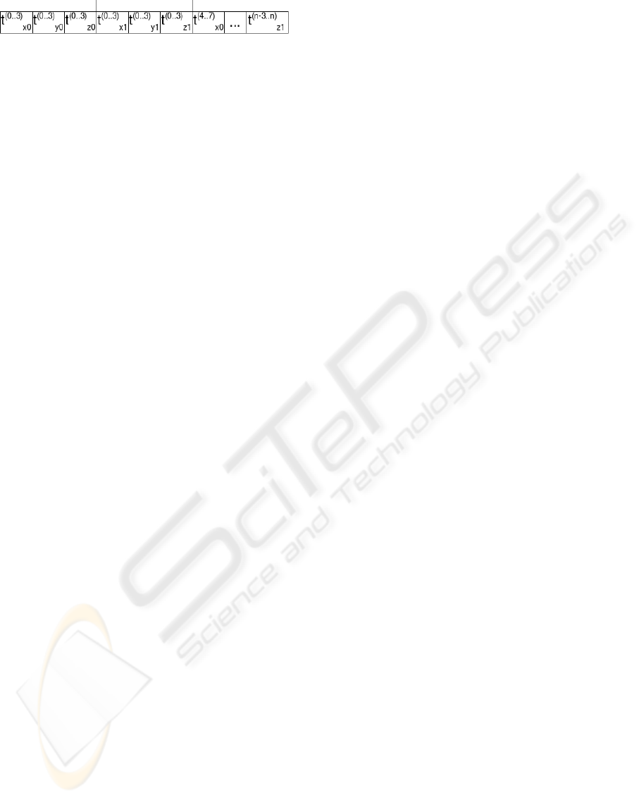
Figure 2: SIMD data structure.
found (and a triangle identifier, ray parameter and
parametric coordinates at the intersection if so).
As was stated in the algorithm description, during
tree traversal each node receives a list of intersecting
rays. This list is local for each node, and stores for
each ray the entry and exit values of the parameters of
the ray for the voxel (t
0x
,t
0y
,t
0z
,t
1x
,t
1y
,t
1z
), since they
depend on the current node. A pointer to the global
structure which stores the rest of the ray information
is also stored per ray.
This data will be processed by SIMD operations;
therefore for maximum performance they should be
stored with a well known SIMD data structure cre-
ated by taking four objects and substituting each field
of the original structure with a vector with the cor-
responding components of the objects. An array of
these structures substitutes the original array of ob-
jects (Figure 2). In this figure, t
(a..b)
xi
represents the
values of the x component of the t parameter for the
four rays in positions a to b. i is 0 for entry and 1
for exit parameters. The same applies to y and z. If
the number of rays is not a multiple of four, the last
packet will be incomplete and will be filled with bo-
gus data which will not be taken into account in the
final results.
Each node gets a ray list, and must generate a new
list for each child. A ray stack is used to prevent dy-
namic memory overhead. On tree construction, mem-
ory is allocated for a large enough stack. For each
traversal, that stack is initialized with all the rays to be
intersected and sent to the root node. The ray lists for
the following nodes visited will be pushed and poped
into the stack as needed, avoiding the need to allocate
memory in each step.
Each node receives on the top of the stack the rays
which intersect it and which should be processed. It
calculates which of these intersect its first child, and
pushes them into the stack. The child gets these new
rays. Upon finishing processing the first child node,
the rays sent to the child are removed from the stack,
and the same process is done for the second child.
This procedure ensures that only the rays which inter-
sect one of the children need to be stored in the stack.
2.3.4 Ray-Triangle Computation
Two variants have been used for ray-triangle intersec-
tions:
• The standard Moller-Trumbore algorithm (M
¨
oller
and Trumbore, 1997), which tests intersection of
one ray with one triangle.
• A variation on the previous one, optimized, with
normals and various intermediate results precal-
culated, with the data of four triangles packed, and
making at the same time the intersection of one
ray with four triangles with SSE.
The results are better (both in time and memory use)
with the second option, (which requires lower depth
trees), and therefore this option was used in tests.
3 PERFORMANCE
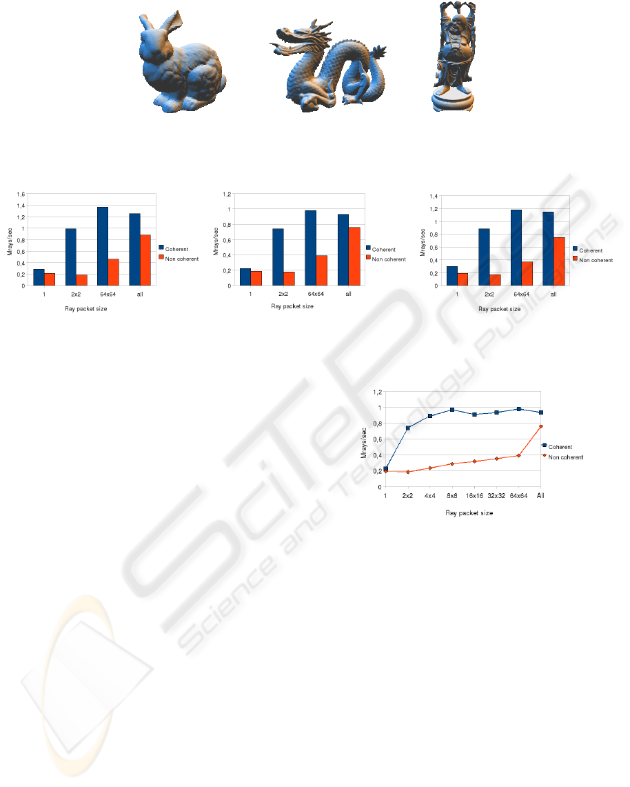
To study the efficiency of this algorithm, three differ-
ent scenes were used (see figure 3): Stanford Bunny
(69451 triangles), Stanford Dragon (0,8 million trian-
gles) and Happy Buddha (1,1 million triangles). The
scenes used were the same for all algorithms.
To compare the algorithm proposed, Wald’s algo-
rithms (Section 1.1) were simulated using our own
algorithm but limiting the maximum number of rays
which can be traversed together to 4 and 64x64. The
algorithm proposed is also compared to a classic re-
cursive algorithm which traverses the rays through the
structure one at a time.
The results were obtained for a maximum allowed
depth of the spatial indexing tree of 16, 18, 20, 22 and
24, and the best results were selected. For most of the
cases, depth 20 was optimal. All measurements were
taken on a 2.6 GHz Intel Core2 Duo with 2 GB of
RAM. Only a single core was used.
3.1 Coherent Ray Comparison
For each case, a 100 image animation of the camera
rotating around three different scenes was generated,
and the mean results were taken. Since the rays have
a common origin and cross consecutive pixels in the
image plane, they present high coherence.
Graphs 4 (left), (center) and (right) show the re-
sults obtained for the different scenes and algorithms,
for both coherent and non coherent rays. It can be
seen in these graphs that the classic algorithm is less
efficient in the coherent ray test for all the scenes.
The other three algorithms are noticeably better, since
they parallelize calculations. Among these three algo-
rithms, the version which traverses the structure with
4-ray packets obtains slightly worse results. The two
remaining algorithms obtain the best time results, and
are very similar to each other.
The four-ray packet version almost always paral-
lelizes the computation of the rays, since they are co-
A VECTORIZED TRAVERSAL ALGORITHM FOR RAY TRACING
61
(a) (b) (c)
Figure 3: The three scenes used for our experiments.
Figure 4: Average performance in MegaRays per second when rendering the Stanford Bunny (left), Standord Dragon (center)
and Happy Buddha (right) at a resolution of 1280x1024 pixels.
herent. However, this is not guaranteed to always hap-
pen, and sometimes the algorithms needs to break the
packet. working with a larger number of rays simulta-
neously mean a larger quantity of data to process, so
that the possibilities of having to work with packages
of size smaller than four are smaller.
3.2 Comparison for Non Coherent Rays
In this article it was said that the main advantage ob-
tained from travelling the tree with all the rays simul-
taneously appears when non-coherent rays are used.
These are classified automatically when descending
the indexing tree and the possibilities of having some
rays in the same node (which means being able to par-
allelize the calculations) are much higher, especially
in nodes near the root.
To prove this, a uniform distribution has been gen-
erated which throws random rays in such a way that
the density of the rays is the same for all regions, in
the manner described by (Santalo, 1976; Sbert, 1993).
This distribution of rays is the worst possible sce-
nario, since ray coherence is lowest.
Graphs 4 left, center and right contrast the results
obtained in this scenario to the results for coherent
rays. It can be clearly seen that the results obtained
by the algorithm which traverses the structure with
four ray packets have been notably reduced with re-
spect to those obtained for coherent rays. The results
are very similar to the clasical recursive algorithm,
Figure 5: Average performance in MegaRays/s for different
ray packet sizes for the dragon scene at 1280x1024.
because when taking non-coherent four-ray packets,
the possibilities that the packet is broken in the higher
levels of the tree are very high, and the algorithm de-
generates to the conventional non parallel algorithm.
The algorithm which uses streams of 64x64 rays
obtains better results since it can reorganize the rays,
getting rid of invalid ones and increasing coherence.
In spite of this, our algorithm is able to achieve a
much higher gain, near 4. Since it works with the full
set of rays at the same time (1280x1024 rays), the re-
ordering of the rays when descending the tree is the
best possible one. This fact implies an optimal hard-
ware utilization. Additionally, reducing the number
of traversals to the minimum means that the overhead
of function calls and access to the nodes of the tree
are drastically reduced, which also increases the gain.
Graph 5 shows the mean performance for differ-
ent sizes of the ray packet. For coherent rays, perfor-
GRAPP 2009 - International Conference on Computer Graphics Theory and Applications
62

mance increases rapidly even with a small ray packet.
This is due to the higher probability of finding coher-
ent rays. In contrast, non coherent rays show a slight
ascending trend as the packet size increases. A larger
packet size implies higher probabilities of being able
to parallelize the calculations; the maximum possi-
ble efficiency is obtained with our algorithm since the
packet contains all the available rays.
4 CONCLUSIONS
Until now, acceleration techniques for ray-tracing
were useful only when it was easy to find coherent
rays to process in parallel. This article introduces a
ray tracing algorithm which instead of traversing the
spatial indexing of the scene once per ray or per ray
packet, it traverses the tree only once with all rays si-
multaneously (or a maximum of eight times if the rays
have director vectors of different sign).
This technique has been shown to present the fol-
lowing advantages: It can extract a higher level of
parallelism in ray processing, even for non coherent
rays, and a node will be visited at most eight times,
resulting in minimization of memory accesses.
Future work includes disabling the ray stack
scheme when the number of rays in a node is small,
to increase efficiency, studying wider SIMD arquitec-
tures, since speedup should be higher (Benthin et al.,
2006), out of core extensions and implementation on
GPUs. A battery of tests with large complete scenes
will validate applicability in real-world scenarios.
ACKNOWLEDGEMENTS
This article has been partially financed by projects
TIN2004-07672-C03-02 of the Spanish Ministry
of Education and Science, and P06-TIC-01403 of
the Junta de Andaluc
´
ıa and the European Union
(FEDER).
REFERENCES
Appel, A. (1968). Some techniques for shading machine
renderings of solids. In AFIPS 1968 Spring Joint
Computer Conf., volume 32, pages 37–45.
Benthin, C., Wald, I., Scherbaum, M., and Friedrich, H.
(2006). Ray tracing on the cell processor. rt, 0:15–
23.
Boulos, S., Wald, I., and Benthin, C. (2008). Adaptive ray
packet reordering. Interactive Ray Tracing, 2008. RT
2008. IEEE Symposium on, pages 131–138.
Carr, N. A., Hall, J. D., and Hart, J. C. (2002). The ray
engine. In HWWS ’02, pages 37–46, Aire-la-Ville,
Switzerland. Eurographics Association.
Christen, M. (2005). Ray tracing on gpu. Master’s thesis,
University of Applied Sciences Basel, Switzerland.
Foley, T. and Sugerman, J. (2005). Kd-tree acceleration
structures for a gpu raytracer. In HWWS ’05, pages
15–22, New York, NY, USA. ACM.
Gribble, C. P. and Ramani, K. (2008). Coherent ray tracing
via stream filtering. Interactive Ray Tracing, 2008. RT
2008. IEEE Symposium on, pages 59–66.
Hanrahan, P. (1986). Using caching and breadth-first search
to speed up ray-tracing. In Proceedings on Graphics
Interface ’86/Vision Interface ’86, pages 56–61.
Intel Corporation (2008). Intel 64 and IA-32 Architectures
Software Developer’s Manual Volume 1: Basic Archi-
tecture.
Jensen, H. W. (1996). Global Illumination Using Photon
Maps. In Rendering Techniques ’96, pages 21–30.
Mahovsky, J. and Wyvill, B. (2006). Memory-conserving
bounding volume hierarchies with coherent raytrac-
ing. Comput. Graph. Forum, 25(2):173–182.
M
¨
oller, T. and Trumbore, B. (1997). Fast, minimum storage
ray-triangle intersection. journal of graphics tools,
2(1):21–28.
Noguera, J. M. and Ure
˜
na, C. (2007). Un algoritmo de
recorrido vectorizado para ray-tracing. In CEDI-
CEIG’07: Proceedings of the XVII Congreso Espa
˜
nol
de Inform
´
atica Gr
´
afica, pages 41–50.
Pharr, M., Kolb, C., Gershbein, R., and Hanrahan, P. (1997).
Rendering complex scenes with memory-coherent ray
tracing. In SIGGRAPH ’97, pages 101–108.
Purcell, T. J., Buck, I., Mark, W. R., and Hanrahan, P.
(2002). Ray tracing on programmable graphics hard-
ware. ACM Transactions on Graphics, 21(3):703–
712.
Revelles, J., Ure
˜
na, C., and Lastra, M. (2000). An ef-
ficient parametric algorithm for octree traversal. In
WSCG’2000, pages 212–219.
Santalo, L. A. (1976). Integral geometry and geometric
probability. Addison-Wesley, Massachusetts (etc.).
Sbert, M. (1993). An integral geometry based method for
fast form-factor computation. Computer Graphics Fo-
rum (Eurographics ’93), 12(3):409–420.
Wald, I. (2004). Realtime Ray Tracing and Interactive
Global Illumination. PhD thesis, Saarland University.
Wald, I., Benthin, C., Wagner, M., and Slusallek, P. (2001).
Interactive rendering with coherent ray tracing. In
Computer Graphics Forum, volume 20(3), pages 153–
164.
Wald, I., Gribble, C. P., Boulos, S., and Kensler, A. (2007).
SIMD Ray Stream Tracing. In Symposium on Interac-
tive Ray Tracing, Conference Program, page 24.
A VECTORIZED TRAVERSAL ALGORITHM FOR RAY TRACING
63
