
GRAYTONE IMAGE METAMORPHOSIS USING 3D
INTERPOLATION FUNCTION
Marcin Iwanowski
Institute of Control and Industrial Electronics
Warsaw University of Technology
ul.Koszykowa 75, 00-662 Warszawa Poland
Keywords:
Image metamorphosis, Morphing, Morphological image processing.
Abstract:
Image metamorphosis process produces deformation sequence which transforms one input image into another
one. The method described in the paper applies morphological approach to achieve this goal. It is based on
morphological interpolation which makes use of the interpolation functions produced from geodesic distance
functions. The described method allows applying this approach to graytone images via its 3D umbra. It
produces 3D interpolation function. Its thresholding at given level followed by inverse umbra transform allows
obtaining frame of the interpolated sequence.
1 INTRODUCTION
This paper describes a method for graytone image
metamorphosis (also called morphing) by means of
binary morphological interpolation (Meyer, 1996;
Serra, 1996; Beucher, 1998; Iwanowski and Serra,
2000; Iwanowski, 2000). Interpolation between two
images consists in generating a sequence of inter-
mediary images, content of which is transformed
from the content of first input image (initial) into the
content of the second one (final). A method pro-
posed in the paper is based on the method introduced
in (Meyer, 1996), where a content of the interpolated
image is obtained by a thresholding of the interpola-
tion function, which is computed from the morpho-
logical geodesic distance functions. Using increas-
ing threshold values results in production of succes-
sive images which creates the interpolation sequence
converting one input image into another. The novelty
of the proposed method is an application of binary
interpolation into graytone images. This is achieved
through an umbra transform, which converts 2D gray-
tone image into 3D binary one. The graytone im-
ages which are morphed are first converted into their
umbras. To interpolate between umbras the method
based on interpolation function in 3D is applied. Con-
trary to methods that already appeared in the litera-
ture (Meyer, 1996; Iwanowski, 2000), the proposed
one interpolates between 3D binary images - umbras
of input graytone images. The interpolated 3D shape
is transformed back into graytone image. By pro-
ducing interpolated image at increasing levels the in-
terpolation sequence (or: morphing sequence) is ob-
tained.
The methods of the morphological interpola-
tion consisting in creation of the intermediary two-
dimensional images between two given ones (’inter-
frame’ interpolation) are developed since 1994. Two
principal approaches were introduced. The first one,
based on the morphological median, was presented
in (Beucher, 1998; Serra, 1996). It is a flexible ap-
proach, which is applicable to any kind of image:
binary, mosaic and graytone. In (Iwanowski and
Serra, 1999) the area of applications of this method
was extended into color images, by using a lexico-
graphic ordering of colors in the comparative color
space. Another approach is represented by the in-
terpolation function method introduced in (Meyer,
1996). This method is based on the function which
describes the relative distance between the objects
and can be applied to binary and mosaic images.
The results of further research (Iwanowski and Serra,
2000) allowed combining the morphological interpo-
lation with affine transform. A different approach to
morphological interpolation was presented in (Soille,
1991), which can be called - contrary to previously
described - an ’intraframe’ interpolation. It deals with
a single incomplete image and it reconstructs the im-
5
Iwanowski M. (2009).
GRAYTONE IMAGE METAMORPHOSIS USING 3D INTERPOLATION FUNCTION.
In Proceedings of the Fourth Inter national Conference on Computer Vision Theory and Applications, pages 5-9
DOI: 10.5220/0001754400050009
Copyright
c
SciTePress

age surface starting from the contour lines. This ap-
proach makes use of the geodesic distance function
obtained by the geodesic propagation.
The morphological approach is automatic in such
a sense that it does not require control points, as clas-
sic morphing methods does. Lack of input parameters
places this method together with well-known cross-
dissolving (Wolberg, 1990). It produces however to-
tally different transformation between images. Cross-
dissolving produces a kind of blending while morpho-
logically interpolated sequence contains the change of
shape of objects on the images.
The paper is organized as follows. Section 2 de-
scribes the classic approach to morphological inter-
polation using the interpolation function. Section 3
presents the proposed approach - the way of apply-
ing this interpolation into graytone images. Section 4
shows some results, and finally Section 5 concludes
the paper.
2 MORPHOLOGICAL
INTERPOLATION FUNCTION
This section recalls the principles of binary inter-
polation using the distance function (Meyer, 1996;
Iwanowski, 2000).
2.1 Binary Object
Binary image i.e. image of pixel values equal either 0
or 1, is usually defined in one of two ways. According
to the first one binary image is a mapping from defi-
nition domain D into {0, 1}. According to the second
one, binary image X is a set of pixels of value 1 (fore-
ground pixels). The complement of this set (X
C
) is
referred to as image background. Image X can consist
of many connected components i.e. subsets of image
pixels such that any two pixels belonging to the same
subset can be connected by a path of pixels of value 1
entirely included in this subset. The single connected
component of binary image will be referred to as ob-
ject. The metamorphosis using interpolation function
allows to morph an object on the initial image another
object on the final one.
2.2 The Interpolator
An interpolator provides a transformation which pro-
duces an interpolated object. It is a function of three
principal arguments: two input objects (initial and fi-
nal) and an interpolation level α. An interpolation
level is a real number α such that 0 ≤ α ≤ 1. In
this paper the interpolator is denoted as: Int
Q
P
(α),
where Q represents the initial binary object, P - the
final one. Shapes of interpolated objects are turning
from a shape of the object Q to shape of the object
P. For α = 0, the interpolated image is equal to the
initial one (Int
Q
P
(0) = Q); for α = 1 - to the final im-
age (Int
Q
P
(1) = P). A sequence of interpolated images
produced for increasing values of α is an interpola-
tion sequence.
2.3 Interpolation Method
The way of defining the interpolator depends on the
mutual relation between input objects. First, the case
of nested objects will be considered where objects lo-
cated on the initial image are included in appropriated
objects on the final image. Later on, the general case
of any two images will be described.
Let X and Y be nested objects (X ⊂ Y). The in-
terpolation function proposed in (Meyer, 1996) is de-
fined as:
int
Y
(X)[p] =
d
Y
(X)[p]
d
Y
(X)[p] + d
X
C
(Y
C
)[p]
, (1)
where X
C
and Y
C
stand for the complements of
binary images X and Y respectively. d
A
(B) stands for
the geodesic distance function describing the distance
to B inside A (B ⊂ A). Geodesic distance is defined
as the length of the shortest path connecting given
pixel in Y \ X with the set X. In digital grid various
ways of computing the distance function are in com-
mon use. The simplest way is propagation in either
4- or 8-connectivity in 2D and 6,18 or 26 connectiv-
ity in 3D. This however is not an Euclidean distance.
The latter could be obtained using specialized algo-
rithms (Vincent, 1991).
The interpolator based on the Eq. 1 is defined as:
Int
X
Y
(α) = T
[α]
(int
Y
(X)), (2)
where T
[α]
stands for the thresholding operator at
level α which sets 1 for graylevels below threshold α,
and 0 otherwise.
The case of two input objects which are not nested
(but which have a non-empty intersection) is split into
two interpolations between nested sets.
Let P and Q be the initial and final objects - nested
or intersected. A final result of the interpolation at
given level α is obtained as an sum of two interpola-
tions of nested objects:
Int
Q
P
(α) = Int
P∩Q
P
(α) ∪ Int
P∩Q
Q
(1− α). (3)
The interpolator in the general case (defined by
the Eq. 3) is based on two interpolators. Each of
VISAPP 2009 - International Conference on Computer Vision Theory and Applications
6

them transforms the input image into the intersection
of both input images. This approach requires two in-
terpolation functions. In order to speed up with the
computations, the single function can be computed.
This case is described in section 3.
The interpolated object at level α = 0.5 is located
in the midway between both input objects. This object
is also referred to as morphological median (Beucher,
1998) defined as:
M = ∪
λ≥0
{((P∩ Q) ⊕ λB) ∩ ((P∪ Q) ⊖ λB)}, (4)
where ⊕ stands for morphological dilation and ⊖
- for erosion.
3 METAMORPHOSIS OF
GRAYTONE IMAGES
3.1 Umbra
Let f : D → V be two-dimensional graytone image
where: D = {0, 1, ..., x
max
− 1} × {0, 1, ..., y
max
− 1}
is the set of pixels coordinates - image definition do-
main and V = {0, 1, ..., g
max
− 1} is set of possible
graytones. x
max
and y
max
are sizes of graytone image
and g
max
is the highest possible graytone value of this
image.
Graytone image can be transformed into 3D um-
bra, which is 3D binary image - a ’relief’ of a terrain
whose map is the input 2D graytone image. The um-
bra transformation is defined as follows:
U[ f ] =
(p, q) ∈ D × V : f(p) ≥ q
. (5)
The above equation describes the transformation
which converts 2D graytone image into 3D umbra.
The inverse transformation, which transforms umbra
back into graytone image, is denoted as follows:
f = U
−1
[X] ⇔ X = U[ f ]. (6)
3.2 Interpolation Function for Graytone
Images
Let f
A
and f
B
be to input graytone images. In the first
step their umbra are computed:
X
A
= U[ f
A
] ; X
B
= U[ f
B
]. (7)
In order to produce the interpolation function,
their sum and intersection have to be computed, re-
spectively:
X
∩
= X
A
∩ X
B
= U[ f
A
∧ f
B
], (8)
X
∪
= X
A
∪ X
B
= U[ f
A
∨ f
B
], (9)
where ∧ and ∨ stand for the point-wise minimum
and maximum of two graytone images, respectively.
These two 3D binary objects are always nested: X
∩
⊂
X
∪
. Owing to this, the geodesic distance functions in
X
∪
\ X
∩
can be computed (for any input images) and
combined together to obtain the interpolation function
according to the Eq. 1.
To simplify the calculations of the interpolations
function, single function can be computed instead of
two as stated in the Eq. 3. Let define the interpola-
tion function between intersection X
∩
and union X
∪
denoted by Int
X
∩
X
∪
. The following relation holds:
Int
X
∩
X
A
(α) = Int
X
∩
X
∪
(α) ∩ X
A
, (10)
Int
X
∩
X
B
(α) = Int
X
∩
X
∪
(α) ∩ X
B
. (11)
The result of thresholding of the interpolation
function have finally to be converted from the um-
bra form into graytone image using U
−1
transform
(Eq. 6). The complete interpolator can be thus for-
mulated as follows:
f
α
= U
−1
h
Int
X
∩
X
∪
(α) ∩ X
A
∪ (Int
X
∩
X
∪
(1− α) ∩ X
B
)
i
.
(12)
Having in mind earlier considerations the above
equation can be re-written as follows:
f
α
=
U
−1
h
Int
X
∩
X
∪
(α)
i
∧ f
A
∨
U
−1
h
Int
X
∩
X
∪
(1− α)
i
∧ f
B
,
(13)
where f
α
stands for the morphologically interpo-
lated graytone image at level α.
Similiarily to the binary case, in the graytone one,
the image f
0.5
is referred to morphological median of
graytone images (Beucher, 1998).
By producing the interpolated images at increas-
ing levels, the sequence of frames is computed - the
interpolation sequence.
4 RESULTS
Figure 1 shows the interpolation sequence produced
using the proposed method starting from two in-
put test images containing rectangles of different
graytones. The sequence consists of 6 interpolated
GRAYTONE IMAGE METAMORPHOSIS USING 3D INTERPOLATION FUNCTION
7
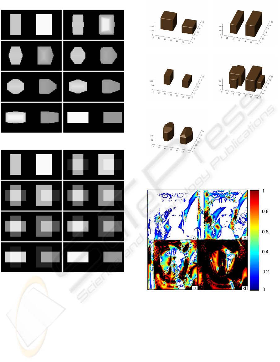
Figure 1: Morphological interpolation of test images.
Figure 2: Cross-dissolving of test images.
frames, generated for equidistanced interpolation lev-
els: 0.14;0.18;0.43;0.57;0.72;0.86. The shapes of
objects on the sequence are changing from the ini-
tial to the final image. In the same time the gray-
value assigned to every rectangle is varying accord-
ingly. Comparing to the alternative way of producing
the image metamorphosis - cross-dissolving shown in
Fig. 2, the morphological interpolation gives a real
change of shape instead of linear combination of pix-
els as cross-dissolving method generates. The umbras
of graytone images are shown in Fig. 3. Pictures 3(a)
and (b) show input images, picture (c) shows the inter-
section of both, (d) - the union. Picture 3(e) presents
the umbra of interpolated image at level α = 0.5
(which is equivalent to morphological median of im-
(a) (b)
(c) (d)
(e)
Figure 3: Umbra of test images: (a),(b) input images, (c) -
their intersection, (d) - sum, (e) median image.
Figure 4: Cross-section of interpolation function for various
values of ’z’-coordinate: (a) z = 70; (b) z = 110; (c) z = 150;
(d) z = 190.
ages shown in (a) and (b)).
The result of morphological interpolation of
real images are shown in Fig. 5. The ’lena’ image
is morphed into ’baboon’. This time the whole
sequence (including input images) consist of 12
images, which was produced for interpolation levels:
0;0.09;0.18;0.27;0.36;0.45;0.54;0.63;0.72;0.81;
0.9;1. The cross-sections of 3D interpolation func-
tion are shown in Fig. 4. These cross-sections was
produced by cutting the 3D interpolation function
at various levels along the ’z’-coordinate. White
VISAPP 2009 - International Conference on Computer Vision Theory and Applications
8
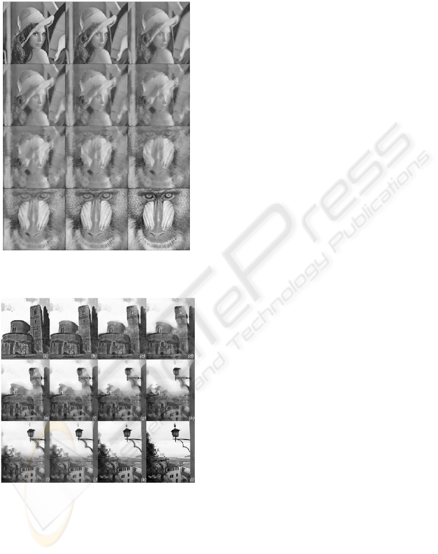
Figure 5: First morphing sequence obtained by morpholog-
ical interpolation.
Figure 6: Second morphing sequence.
regions belongs to the intersection of both umbras
(where interpolation function is not computed), black
regions - to the regions which are above the union
of them (here again the interpolation function is not
computed), colors refer to values of the interpolation
function (between 0 and 1).
Another example of interpolation sequence is
shown in Fig. 6. This sequence counts 16 frames pro-
duced, as in the prvious case, for equidistanced con-
secutive values of interpolation levels.
5 CONCLUSIONS
In the paper a method for transforming one graytone
image into another was proposed. The method is
based on the morphological interpolation using the
interpolation function. 2D graytone image image is
transformed into 3D binary image (its umbra) and in-
terpolated morphologically. The interpolated 3D ob-
ject is transformed back into graytone image. The
method can be applied to produce image metamor-
phosis for visual special effects. It is fully automatic,
the only parameter is the number of frames of the out-
put morphing sequence. Comparing with the cross-
dissolving the morphological interpolation produces
a real change of shapes of objects instead of blending
produced by the cross-dissolving. Further research
plans includes the application of the proposed ap-
proach to color images.
REFERENCES
Beucher, S. (1998). Interpolation of sets, of partitions and
of functions. In Mathematical morphology and its ap-
plication to image and signal processing. Kluwer.
Iwanowski, M. (2000). Application of mathematical mor-
phology to interpolation of digital images. Warsaw
University of Technology, School of Mines of Paris.
Iwanowski, M. and Serra, J. (1999). Morphological inter-
polation and color images. In Proc.of: 10-th Interna-
tional Conference on Image Analysis and Processing
ICIAP99. IEEE.
Iwanowski, M. and Serra, J. (2000). Morphological-affine
object deformation. In Mathematical morphology
and its application to image and signal processing.
Kluwer.
Meyer, F. (1996). Morphological interpolation method for
mosaic images. In Mathematical morphology and its
application to image and signal processing. Kluwer.
Serra, J. (1996). Hausdorff distance and interpolations. In
Mathematical morphology and its application to im-
age and signal processing. Kluwer.
Soille, P. (1991). Spatial distributions from contour lines:
an efficient methodology based on distance transfor-
mations. J. of Visual Communication and Image Rep-
resentation, 2.
Vincent, L. (1991). Exact euclidean distance function by
chain propagations. In Proc. IEEE Computer Vision
and Pattern Recognition. IEEE.
Wolberg, G. (1990). Digital Image Warping. IEEE Com-
puter Society Press.
GRAYTONE IMAGE METAMORPHOSIS USING 3D INTERPOLATION FUNCTION
9
