A SCALABLE AND OPEN SOURCE LINEAR POSITIONING
SYSTEM CONTROLLER
M. C. Medeiros, A. J. A. Fernandes, C. A. Teixeira and M. Grac¸a Ruano
Centre for Intelligent Systems, University of Algarve, Gambelas, Faro, Portugal
Keywords:
Automatic Positioning, Open Source Software, Scalable Systems, Ultrasound Measurements.
Abstract:
This paper is on the implementation of a dual axis positioning system controller. The system was designed
to be used for space-dependent ultrasound signal acquisition problems, such as pressure field mapping. The
work developed can be grouped in two main subjects: hardware and software. Each axis includes one stepper
motor connected to a driver circuit, which is then connected to a processing unit. The graphical user interface
is simple and clear for the user. The system resolution was computed as 127µm with an accuracy of 2.44µm.
Although the target application is ultrasound signal acquisition, the controller can be applied to other devices
that has up to four stepper motors. The application was developed as an open source software, thus it can be
used or changed to fit different purposes.
1 INTRODUCTION
In the scientific field precision is everything. A
scientist cannot conduct a responsible scientific expe-
riment if the precision of the process is not controlled.
Laboratory experiments involving ultrasound deals
normally with space-dependent parameters, such as
time-of-flight or pressure. Manual adjustment can in-
duce human errors, that can be eliminated by using
a reliable and automatic positioning system. In the
scientific community, the open-source software con-
cept is often referred. It refers to computer appli-
cations whose source code is available and under an
open-source license to study, change or tune the soft-
ware, and to redistribute in the modified or unmodi-
fied form.
This paper presents the necessary hardware and
software to control a linear positioning system. The
main application of this system is the acquisition of
space-dependent ultrasound signals. The developed
controller is an evolution to the system supplied by the
manufacturer. The proposed controller is supported
in Unix/Linux operating systems (OSs) and the con-
nection with the personal computer is accomplished
through an USB interface, instead of the nowadays
rare parallel port (Arrick Robotics, nd).
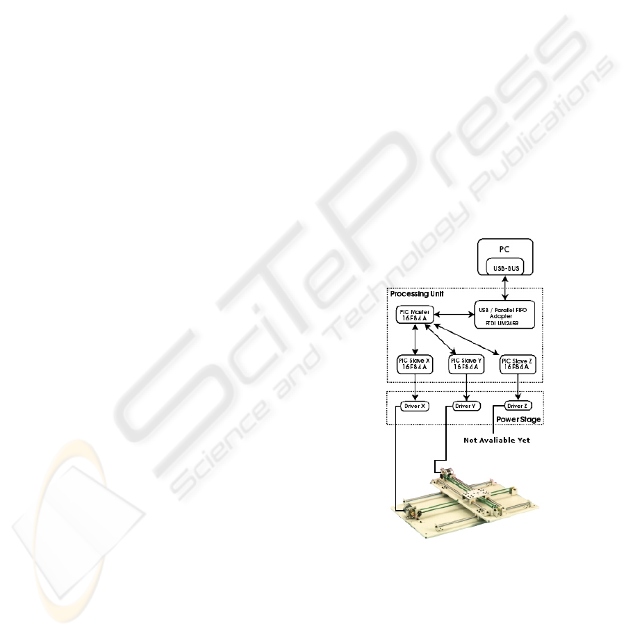
Figure 1: Hardware interconnection.
2 HARDWARE
A schematic representation of the overall hardware
used is presented in Figure 1.
The main part of this project is the positioning
table (Arrick robotics, model XY-18). This table
has two belt-driven axis with a moving range of
410
Medeiros M., Fernandes A., Teixeira C. and Ruano M. (2009).
A SCALABLE AND OPEN SOURCE LINEAR POSITIONING SYSTEM CONTROLLER.
In Proceedings of the International Conference on Biomedical Electronics and Devices, pages 410-413
DOI: 10.5220/0001549804100413
Copyright
c
SciTePress

464.8 mm. Each axis includes a stepper motor
(Telcomotion, 4H5618C2906), which is responsible
for the automatic motion of a top plate (mobile point).
Each stepper motor has a resolution of 0.9 degrees per
step with an accuracy +/- 5%. The top plate is where
the load (transducers, hydrophones, or a third axis)
is to be attached. Each axis has two limit-switches,
which prevents from equipment damage and are also
reference points (Arrick Robotics, nd).
2.1 Power Stage
Between the Processing Unit (PU) and each mo-
tor there is a driver circuit, responsible to adapt the
current sent by the PU (in the range of mA) to a
current necessary (in the range of A) to move the
motor with high torque. To mention that all stepper
motors work in half-step mode (Yeadon and Yeadon,
2001).
2.2 Processing Unit
For the Processing Unit (PU) we used three microcon-
trollers PIC 16F84A (Microchip Technology, 2001)
from Microchip, to control both stepper motors.
One of the microcontrollers is called the PIC
Master (PICM), which receives orders from the PC.
The information from the PC to the PU is sent in a
group of 10 Bytes. The information transmitted is:
• target axis;
• direction;
• speed;
• number of steps;
• synchronization bytes.
After data processing the PICM starts the commu-
nication with the PIC Slaves (PICSs), that are
connected to the target stepper motors through the
driver circuit. Whenever a certain motor has to move
a step, PICM signals the corresponding PICS, which
only has to change the output pins state in order to
give a step.
If a switch (at the limits) is pressed, the PICS
that detected it, signals the PICM. When the move-
ment stops, the PICM sends a feedback byte to the
PC, on which it informs if the operation was or not
successful.
Whenever both stepper motors have to move the
same distance (same number of steps), they move at
the same time. Otherwise, only one motor moves at a
time.
The PU is designed to allow to control up to four
axis. The PICM has some pins that are not connected
to anything and can be used to add a new axis. If
the new axis don’t have any special requeriment, the
firmware of the PICSs will all be the same. This char-
acteristics makes our system scalable.
2.3 PC/PU interface
The interface between the PC and the PU is done
through a USB to parallel FIFO module (FTDI
UM245R) (FTDI Ltd, 2005), integrated in the PU.
The UM245R is a module with a lot of poten-
tial, since that it’s not needed to develop USB-specific
firmware to handle the USB protocol. Besides this,
it’s possible to communicate through a Synchronous
Bit Bang Mode that allows to keep a synchronous
communication.
3 SOFTWARE
The software for this project was developed in an
open source environment, so it can be used in other
applications that involves stepper motors.
In Unix/Linux environments as in others OS, the
hardware is controlled by specific programs called de-
vice drivers. In particular case of Linux, this pro-
grams can be loaded to kernel at run time, and they are
called kernel modules. With this modules it’s possi-
ble in user mode, to communicate with the hardware
without direct access, hiding all the low level func-
tions.
One of the requirements was to develop the soft-
ware as a Python module, to be integrated in other
Python programs (Teixeira et al., 2006). Since a func-
tional userspace library in C language and at the mo-
ment there isn’t any Python module for FTDI modu-
les for Linux, it was necessary to create a C Python
Extension (van Rossum, 2008). This enabled the in-
tegration of the necessary C code to control the linear
positioning table.
Figure 2 presents the software structure. The main
program is called table.py and implements a state ma-
chine that handles computer and user events. The
interfaceGUI.py file is responsible to create all the
graphical interface and the methods to access to all
the values that the user can change or configure. A
Python module called pylab included in matplotlib
library (Matplotlib Project, nd) was used to display
the motors movement. The options.py file includes
classes and methods for all the stepper motors op-
tions.
The session is saved in two data files, in order to
keep the data for next sessions. The options file has
the characteristics of each motor, and the settings file
A SCALABLE AND OPEN SOURCE LINEAR POSITIONING SYSTEM CONTROLLER
411
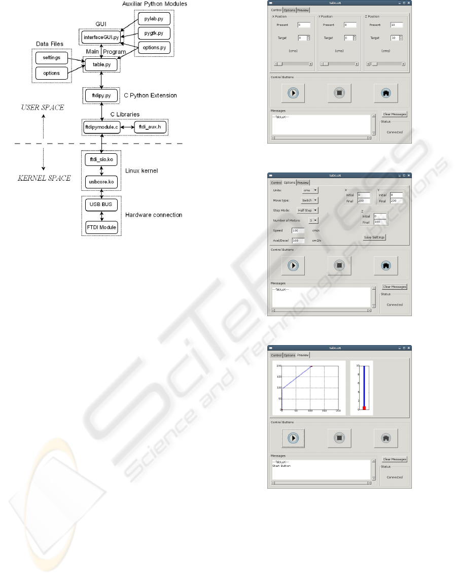
Figure 2: Software structure.
has the present positions of the motors after the move-
ment.
As mentioned before, in order to interface the C
libraries, a file named ftdipymodule.c was created as
an C Python Extension. This file is a wrapper between
C and Python languages.
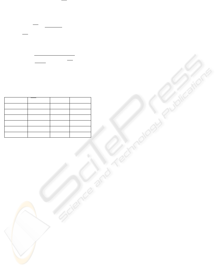
4 GRAPHICAL USER
INTERFACE
The user interface was developed in GTK+, because
it’s portable, and his use with Python is easy with the
pygtk module (GNOME Project and PyGTK Team,
2006). The application front-end is presented in Fi-
gure 3.
We can define the amount of movement for each
motor or simply scroll the bar to the position, we can
also control the movement with the start, stop and
home buttons. In the messages box, it can be seen
a small report of what is happening, and check the
device status (connected or disconnected).
From the Options Tab (see Figure 4), its possible
to choose the metric units, move type, the step mode,
number of motors, speed, acceleration and the axis
size.
The output can be seen in Output Tab (see Figure
5), where it’s represented the table (X and Y axis) on
the left side, and a vertical bar (Z axis) on the right
side. When the top plate is moving the output is ge-
nerated according to the amount of movement.
Figure 3: Control tab.
Figure 4: Options tab.
Figure 5: Preview tab.
5 RESULTS & DISCUSSION
In order to determine how precise the system is, travel
distances for different number of steps were assessed
in order to verify how the system behaves. Six diffe-
rent number of steps were tested: 100, 200, 400,
600, 800 and 1000. For each one, ten measurements
(N = 10) were taken using a caliper ruler (accuracy
of 20 µm). The ratio between a measure (X) and the
BIODEVICES 2009 - International Conference on Biomedical Electronics and Devices
412
number of steps (n), corresponds to the length of a
single step (X
N
). So, the mean (X
N
) of N values of
X
N
, is assumed to be a normalized mean and can be
computed by Equation 1.
X
N
=
∑
N
k=1
X
N
k
N
(1)
After the X
N
values of each test have been deter-
mined, their Standard Deviation (σ) can be computed
by Equations 2.
σ =
s
1
N − 1
N
∑
k=1
(X
N
k
− X
N
) (2)
The Variance (σ
2
) can easily be computed as the
positive square-root of σ.
Table 1: Results.
n (steps) X
N
(µm) σ (µm) σ
2
(µm)
100 125.94 1.22 1.49
200 126.38 0.64 0.41
400 126.64 0.49 0.24
600 126.52 0.43 0.19
800 126.84 0.36 0.13
1000 126.76 0.23 0.05
From the values in Table 1, it can be seen that µ
presents a stable value on all the tests, with an accep-
table difference between them. Also, as the number
of steps increases, the values of σ and σ
2
decreases.
This happens becasuse of the initial inertia and im-
precisions of the system. The mechanical parts of the
table applies some forces to the system (belt has ten-
sion, top-plate has weight and the steel shafts have
friction) that will result in the resistance to a change
on its state of motion.
According to the data presented in Table 1, the re-
solution of each axis of the system can be defined has
127 µm. Due to the real application of the system,
small travel distances (n < 100 steps) will be often
used and the worst case (n = 100 steps) is used to de-
termine the accuracy value. For a 95 % confidence in-
terval (Normal distribuition) the accuracy is 2.44 µm
(2σ for n = 100 steps).
6 CONCLUSIONS & FUTURE
WORK
The system developed works as a linear positioning
system using step motors. It was created a hardware
driver in a modular way, which enables the addition
of a new axis easily. The software is open-source and
can be used and modified according to the user needs.
The motor movements have an acceptable resolution
and accuracy. The developed controller is an actu-
alized version of the system supplied with the linear
table. In the future this application can be used for ul-
trasound signal processing, and new improves can be
made, like operation in full-step mode and adding up
to four axis.
REFERENCES
Arrick Robotics (n.d.). X and XY Linear Positio-
ning Tables. Retrieved May 6, 2008, from
http://www.arrickrobotics.com.
FTDI Ltd (2005). UM245R USB-Parallel FIFO
Development Module. Retrieved from
http://www.ftdichip.com.
GNOME Project and PyGTK Team (2006). PyGTK:
GTK+ for Python. Retrieved May 12, 2008, from
http://www.pygtk.org/.
Matplotlib Project (n.d.). Matplotlib / pylab - matlab
style python plotting. Retrieved May 12, 2008, from
http://matplotlib.sourceforge.net.
Microchip Technology (2001). PIC16F84A Data Sheet. Re-
trieved from http://www.microchip.com.
Teixeira, C. A., Ruano, M. G., Ruano, A. E., and Pereira,
W. C. A. (2006). Open source data sensing software
for ultrasonic non-invasive temperature estimation. In
5
o
Congresso Ibero-Americano de Sensores - Ibersen-
sor 2006. Montevideo, 27-29 September. Uruguay.
van Rossum, G. (2008). Extending and Embedding the
Python Interpreter. Retrieved May 12, 2008, from
http://www.python.org.
Yeadon, W. H. and Yeadon, A. W. (2001). Handbook of
small electric motors. McGraw-Hill Professional.
A SCALABLE AND OPEN SOURCE LINEAR POSITIONING SYSTEM CONTROLLER
413
