
A NEW LINEAR ARRAY IMAGING SYSTEM OF ELECTRICAL
AND ULTRASONIC PROPERTIES IN A LIVING BODY
Akira Kimoto, Yuuta Taninaka and Katsunori Shida
Faculty of Science and Engineering, Saga University, Honjyo 1,Saga, Japan
Keywords: Piezoelectric ceramic transducer, Ultrasonic property, Electrical property.
Abstract: In this paper, a new linear array imaging system of ultrasonic and electrical properties in the living body is
proposed. The proposed imaging system measures not only the ultrasonic property of the living body using
the linear arrayed piezoelectric ceramic transducers, but also the electrical property using the surface
electrodes of each piezoelectric ceramic transducer. From these data, ultrasonic and electrical properties in
the same object space are simultaneously reconstructed. In the experiment, propagation time and electrical
voltage of the living body model are measured by the proposed imaging system based on linear arrayed
eight piezoelectric ceramic transducers. Ultrasonic and electrical properties are reconstructed from the
measurement values. It was found that the ultrasonic and electrical properties in the same space could be
reconstructed by the proposed imaging system. Therefore, it is suggested that the proposed imaging system
has potential for application although there are some problems that must be solved.
1 INTRODUCTION
Imaging techniques based on the ultrasonic property
(Opielinski and Gudra, 2000, Simaeys et al., 2000)
or electrical property (Holder et al., 1993, Barber
and Brown, 1984) of a living body are especially
important in medical field, and have been actively
researched. A non-invasive ultrasonic imaging
system using ultrasonic properties of the living body
has been studied for determining the blood flow
velocity distribution and internal organ imaging
(Nitta et al., 1996, Lopez et al., 1992). The electrical
impedance computed tomography using electrical
properties of the living body has also been
developed for imaging of the heart and lungs (Fuks
et al., 1991), temperature distribution measurements
(Conway et al., 1992) and so on.
The aim of our research is to establish a non-
invasive simultaneous imaging system of two
parameters in the living body such as temperature
and a body composition. To achieve it, we propose a
new linear array imaging system of ultrasonic and
electrical properties in the living body. In the
proposed system, the ultrasonic propagation time is
measured by the linear arrayed piezoelectric ceramic
transducers. In addition, the electrical potential is
measured by the surface electrodes of poizoelectric
ceramic transducers (Kimoto and Shida, 2001, 2002).
Therefore, it is possible to measure the ultrasonic
and electrical properties in the same object space
using the proposed imaging system. From these data,
ultrasonic and electrical properties in the living body
are reconstructed. Moreover, two parameters such as
temperature and composition are estimated from
their reconstructed distributions.
In this paper, the imaging system with the linear
arrayed eight piezoelectric ceramic transducers is
established. In the experiment, ultrasonic
propagation time and electrical voltage in 0.1 %
saline solution with acrylic as the living body model
are measured by the proposed imaging system, and
then, the reconstructions of ultrasonic and electrical
properties are demonstrated from their measuremet
values.
2 PRINCIPLE
The ultrasonic and electrical properties in the living
body are generally measured by different sensors. In
the proposed method, they are measured by the same
sensor. Figure 1 shows the measurement method of
the ultrasonic and electrical properties in the living
body. In this method, a linear arrayed piezoelectric
ceramics are used. In figure 1(a), an electrical signal
with a resonance frequency of the piezoelectric
372
Kimoto A., Taninaka Y. and Shida K. (2009).
A NEW LINEAR ARRAY IMAGING SYSTEM OF ELECTRICAL AND ULTRASONIC PROPERTIES IN A LIVING BODY.
In Proceedings of the International Conference on Biomedical Electronics and Devices, pages 372-375
DOI: 10.5220/0001543103720375
Copyright
c
SciTePress
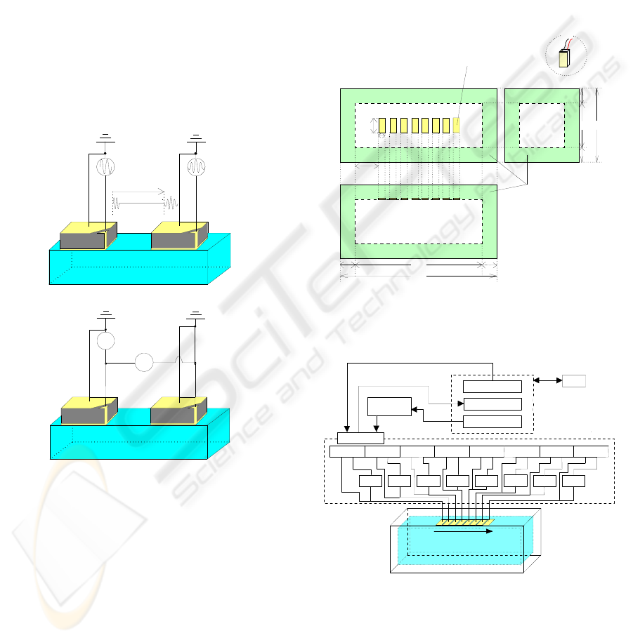
ceramic transducer, S
t
, is applied to a piezoelectric
transducer, and the reflected wave, S
r
is measured by
the other piezoelectric ceramic transducer. From
these signals, the ultrasonic property of the object is
obtained. In figure 1(b), the constant current is
injected between the surface electrodes of a pair of
piezoelectric ceramic transducers and the induced
voltage between each surface electrodes are
measured. The electrical property is obtained from
the induced voltage and injected current. Therefore,
the ultrasonic and electrical properties in the same
object space are obtained using a pair of
piezoelectric ceramic transducers. Moreover, the
reconstructed distributions of the ultrasonic and
electrical properties are respectively obtained from
the measured values by using linear arrayed many
piezoelectric ceramic transducers.
Ultrasonic property
Time of flight
S
t
S
r
(a)
Electrical property
V
I
(b)
Figure 1: Measurement method. (a) Measurement of
ultrasonic property. (b)Measurement of electrical property.
3 MEASUREMENT SYSTEM
Figure. 2 shows the schematic diagram of the
measurement equipment. The rectangular equipment
(40×40×100 mm
3
) was constructed by acrylic plate
and the eight piezoelectric ceramic transducers
(10×5×1 mm
3
) with 2 MHz resonance frequency are
linearly arrayed with the gap of 1 mm at an acrylic
plate inside the equipment. It is filled with the 0.1%
saline solution as the living body model.
Figure 3 shows the outline of the measurement
system. In the ultrasonic measurement, the burst
wave of the five sinusoidal waves with the
amplitude of 10 V and the 2 MHz frequency as the
transmitted wave is given to one of the piezoelectric
ceramic transducers by the function generator. The
reflected wave is measured by each piezoelectric
ceramic transducer. Transmitted and reflected waves
are passed through the AD converter and stored at
the PC. From their waves, propagation time is
obtained.
100
120
40 60
10
10
10
10
25
5
10
Acrylic
Side view
Top view Side view
[mm]
Piezoelectric ceramic
transducer
18234567
0.1 % saline solution
Figure 2: Schematic diagram of experimental equipment
with linear arrayed eight piezoelectric ceramic
transducers.
18
Imaging area
I/O board
AD converter
GPIB board
VI C VI C VI C VI C VI CVI C
VI C
VI C
Switch1 Switch2 Switch3 Switch4 Switch5 Switch6 Switch7 Switch8
PC
Function
generator
Switch box
VI C:V-I converter
Figure 3: Schematic diagram of measurement system.
In the electrical measurement, the sinusoidal
current of 1mA, which sinusoidal voltage with the
amplitude of 1 V and 10 kHz frequency is converted
by V-I converter, is injected between the surface
electrodes of a pair of piezoelectric ceramic
transducers. The voltages induced on rest of surface
A NEW LINEAR ARRAY IMAGING SYSTEM OF ELECTRICAL AND ULTRASONIC PROPERTIES IN A LIVING
BODY
373
electrodes of piezoelectric ceramic transducers are
measured. Each voltage is also digitalized by the AD
converter and stored at the PC.
The ultrasonic and electrical measurements and
the selection of piezoelectric ceramic transducers are
changed using the switching system controlled by
the I/O signal.
4 EXPERIMENT
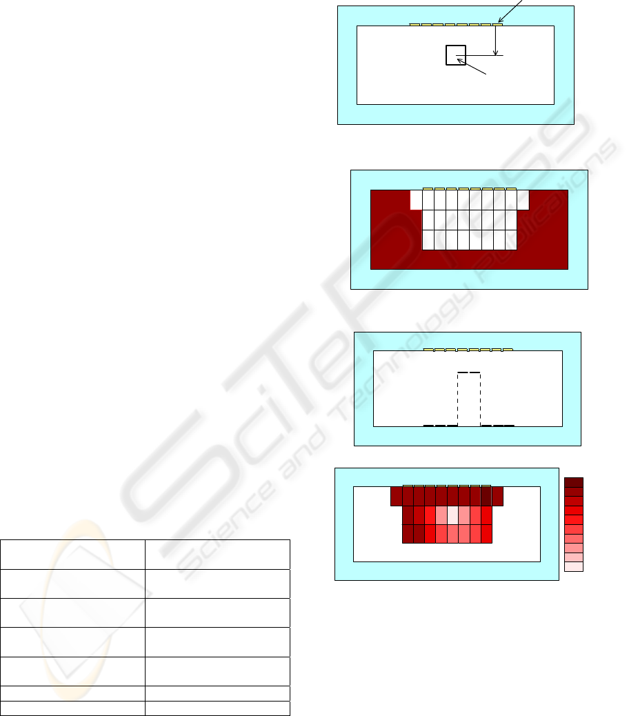
Figure 4 shows the experimental model. 0.1 % saline
solution model, which acrylic (10×10 mm
2
) is
inserted at the position of 15 mm apart from the
piezoelectric ceramic transducers, was prepared. The
ultrasonic and electrical distributions are
respectively reconstructed from the measurement
values of ultrasonic propagation time and electrical
voltage. In this time, propagation time and voltage
for reconstructing the ultrasonic and electrical
distributions were measured as follows.
Propagation time as ultrasonic property was
obtained from transmitted and reflected waves
measured at each piezoelectric ceramic transducer
from No.1 to No.8. Therefore, ultrasonic distribution
was obtained from eight data. In electrical property,
the voltage induced at surface electrode of
piezoelectric ceramic transducer between a pair of
surface electrodes used as current electrodes was
measured. Table 1 shows the combinations of
current and voltage electrodes. Therefore, 56 voltage
values were used for the imaging of electrical
property. In this time, impedance distribution as
electrical property was reconstructed by the
measured data and the numerical calculation using
the finite element method (FEM).
Table 1: Combination of electrical measurement.
Current electrode
numbers
Voltage electrode
number
(1,3), (2,4), (3,5),
(4,6),(5,7),(6,8)
(2), (3), (4),
(5), (6), (7)
(1,4), (2,5), (3,6),
(4,7), (5,8)
(2,3), (3,4), (4,5),
(5,6), (6,7)
(1,5), (2,6),
(3,7), (4,8)
(2,3,4), (3,4,5),
(4,5,6), (5,6,7)
(1,6), (2,7), (3,8) (2,3,4,5), (3,4,5,6),
(4,5,6,7)
(1,7), (2,8) (2,3,4,5,6), (3,4,5,6,7)
(1, 8) (2,3,4,5,6,7)
Figure 5 shows the 26 unknown elements of
impedance estimated by FEM. Impedance values in
other regions are those of 0.1 % saline solution.
Impedance of each element was estimated by the
modified Newton-raphson method as the iterative
method (Kimoto and Shida, 2000).
Acrylic
0.1 % saline solution
Piezoelectric ceramic
transducer
18234567
15 mm
Figure 4: Reconstructed model.
Figure 5: Estimated elements of electrical property.
(a)
1.02
0.80
[%]
(b)
Figure 6: Reconstructed results. (a) The ultrasonic
propagation time. (b)The change ratio of electrical
impedance.
5 RESULTS
Figure 6 shows the reconstructed results of
ultrasonic and electric properties. Figure 6(a) shows
the positon of reflected wave obtained by the
propagation time and the sound speed. In this time,
BIODEVICES 2009 - International Conference on Biomedical Electronics and Devices
374

sound speed was calculated by propagation time
measured in 0.1 % saline solution and 40 mm
distance of equipment. From figure 6(a), it is found
that the boundary of the target in 0.1 % saline
solution is obtained although it was difficult to
detect the construction of the target. Figure 6(b)
shows the impeadace change ratio between 0.1 %
saline solution with and without acrylic at three
iteration. From figure 6(b), it is found that impedace
in the part of acrylic decreased although the
estimated resolution is insufficient. In this system, it
is possible to reconstruct the ultrasonic and electrical
properties by measuremets of propagation time and
voltage. In addition, it is suggested that the
resolution of the reconstructed image would be
improved by combining the ultrasonic and electrical
reconstructed images because their reconstructed
distributions are different.
6 DISCUSSION
The accuracies of reconstructed distributions of
ultrasonic and electrical properties were insufficient.
They are mainly caused by measurement error of the
system and insufficient measured data number. The
measurement system, especially, the switching
system must be improved. Data number will be also
increased by using several measurement
combinations.
In this time, although ultrasonic and electrical
measurements are changed by the switching system,
simultaneous measurements of the ultrasonic and
electrical properties are possible in which one
electrical signal is created from the electrical signal
with the resonance frequency for ultrasonic
measurement and that of the electrical impedance
measurement and is applied to the electrode as an
alternating current.
7 CONCLUSIONS
A new linear array imaging system of ultrasonic and
electrical properties in the living body was proposed.
In the proposed imaging system, the ultrasonic
propagation time is measured by the linear arrayed
piezoelectric ceramic transducers and the electrical
potential is also measured by the surface electrodes
of poizoelectric ceramic transfuces. Therefore, it is
possible to measure the ultrasonic and electrical
properties in the same object space using the
proposed system. From these data, ultrasonic and
electrical properties in the living body are
reconstructed. In the experiment, the ultrasonic and
electrical properties in 0.1 % saline solution with
acrylic as the living body model were reconstructed
from propagation time and voltage measured by the
proposed imaging system. As a result, it was
suggested that the proposed imaging system has
potential for application although there are some
problems that must be solved.
REFERENCES
Opielinski K. J. and Gudra T., 2000, Ultrasound
transmission tomography image distortions caused by
the refraction effect, Ultrasonics, vol.38, pp.424-429
Simaeys B., Philips W., Lemahieu I. and Govaert P., 2000,
Quantitative analysis of the neonatal brain by
ultrasound, Computerized Medical Imaging and
Graphics, vol.24, pp.11-18
Holder D. S., Ed., 1993, Clinical and physiological
applications of electrical impedance tomography, UCL
Press London
Barber D.C. and Brown B.H., 1984, Applied potential
tomography,” J. Phys. E: Sci. Instrum., vol.17, No.9,
pp.723-733
Nitta N., Hagihara K. and Shiina T., 1996, Experimental
Investigation of 3-D Blood Flow Velocity
Measurement, Jpn.J.Appl.Phys., vol.35, Pt.1, 5B,
pp.3126-3130
Lopez H., Loew M.H. and Goodenough D.J., 1992,
Objective Analysis of Ultrasound Images by Use of a
Computational Observer, IEEE Trans. on Med. Img.,
vol.11, No.4, pp.496-506
Fuks L. F., Cheney M., Isaacson D., Gisser D. G. and
Newell J. C., 1991, Detection and Imaging of Electric
Conductivity and Permittivity at Low Frequency,
IEEE Trans. Biomed Eng., vol.38, No.11, pp.1106-
1110
Conway J., Hawley M., Hangnall Y., Amasha H. and
VanRhoon G. C., 1992, Experimental assessment of
electrical impedance imaging for hyperthermia
monitoring, Clin. Phys. Physiol. Meas., vol.13,
Suppl.A, A185-A189
Kimoto A. and Shida K., 2001, Proposal of a New
Multifunctional Measurement Method Using
Piezoelectric Vibrator, Jpn. J. Appl. Phys. Vol.40,
Part1, 6A, pp.4258-4259
Kimoto A. and Shida K., 2002, A proposal of
measurements of conductance and propagation time
for determination of temperature and ingredient in the
living body model, Trans. IEE of Japan, vol.122-E,
No.6, pp.332-337 (in Japanise)
Kimoto A. and Shida K., 2000, Imaging of temperature-
change distribution in the brain phantom by means of
capacitance measurement , IEEE Transactions on
Instrumentation and Measurement, Vol.49, Issue 3,
pp.591-595
A NEW LINEAR ARRAY IMAGING SYSTEM OF ELECTRICAL AND ULTRASONIC PROPERTIES IN A LIVING
BODY
375
