
AN ASIC SOLUTION FOR INTELLIGENT ELECTRODES AND
ACTIVE-CABLE USDED IN A WEARABLE
ECG MONITORING SYSTEM
Geng Yang, Jian Chen, Fredrik Jonsson, Hannu Tenhunen and Li-Rong Zheng
School of Information and Communication Technology
Royal Institute of Technology (KTH), Forum 120, SE-16440 Kista, Stockholm, Sweden
Keywords: Wearable ECG, ASIC, Active-Cable, Intelligent Electrode.
Abstract: This paper describes a digital CMOS Application Specific Integrated Circuit (ASIC) solution with the
complete data acquisition and transmission for the use in a wearable electrocardiography (ECG) monitoring
system. The main particularity of this system is related to the proposed reconfigurable microchip
architecture for an intelligent electrode. The chip area is 2.3 mm
2
in a standard 0.18 µm CMOS technology.
The chip is operating at 24 MHz system clock with 3.3 V power supply for I/O cells and 1.8 V for the core
circuit respectively. The estimated dynamic power dissipation is only 857 µW. The post-layout simulation
results show that the microchip embedded inside an intelligent electrode features ultra low power
consumption and is quite feasible for a hand-held Personal Health Assistant (PHA) which uses a battery as
energy source.
1 INTRODUCTION
The global demographic trend towards an ageing
population is leading to higher probability and
earlier onset of the heart disease, which is the main
cause of death in most countries. In modern
medicine, there are sorts of methods to diagnose
heart disease, such as electrocardiography (ECG),
ultrasound, computerized tomography and so on.
Among these methods, ECG diagnosis can be used
in a wide area due to the advantages of convenience
and low cost (Dong, Zhang and Jia 2008). However,
several unsolved problems still exist in current ECG
monitoring systems, such as high power
consumption, low signal quality and too many
cables.
In this research, we develop a digital CMOS
application specific integrated circuit (ASIC) with
the characteristics of reconfigurable architecture,
high resolution ECG data, ultra low power
consumption and tiny package size. Such an ASIC is
suitable to be embedded inside a paper plaster to
form an intelligent electrode. Moreover, a 3-lead
wearable ECG monitoring system is developed
based on three intelligent electrodes and one single
Active-Cable, with the capability of continuous non-
intrusive ECG signal sampling and real-time ECG
data processing.
Instead of multiple cables in traditional ECG
applications, one single Active-Cable (Yang et al.
2008), with serial communication enabled by
microchips embedded inside intelligent electrodes, is
used to connect all intelligent electrodes together.
ECG data with minimal noise interference can be
achieved due to the new architecture of the
intelligent electrode which enables synchronous
analog/digital (A/D) conversions and signal
processing performed directly on electrodes rather
than inside a portable device (
Hung, Zhang and Tai
2004). Prolonged lifetime is achieved due to the
power efficient ASIC architecture for the intelligent
electrode. This solution does not only dramatically
increase the system energy efficiency and patients'
comfort but also provide high-quality ECG data.
This is an industry-relevant biomedical
application, under cooperation with the paper
industry and the semiconductor industry, which is
still in the research and development phase. The aim
of this design is to develop low-cost disposable
paper-based intelligent electrodes which could be
used both in hospital and home healthcare scenarios.
209
Yang G., Chen J., Jonsson F., Tenhunen H. and Zheng L. (2009).
AN ASIC SOLUTION FOR INTELLIGENT ELECTRODES AND ACTIVE-CABLE USDED IN A WEARABLE ECG MONITORING SYSTEM .
In Proceedings of the International Conference on Biomedical Electronics and Devices, pages 209-213
DOI: 10.5220/0001539802090213
Copyright
c
SciTePress
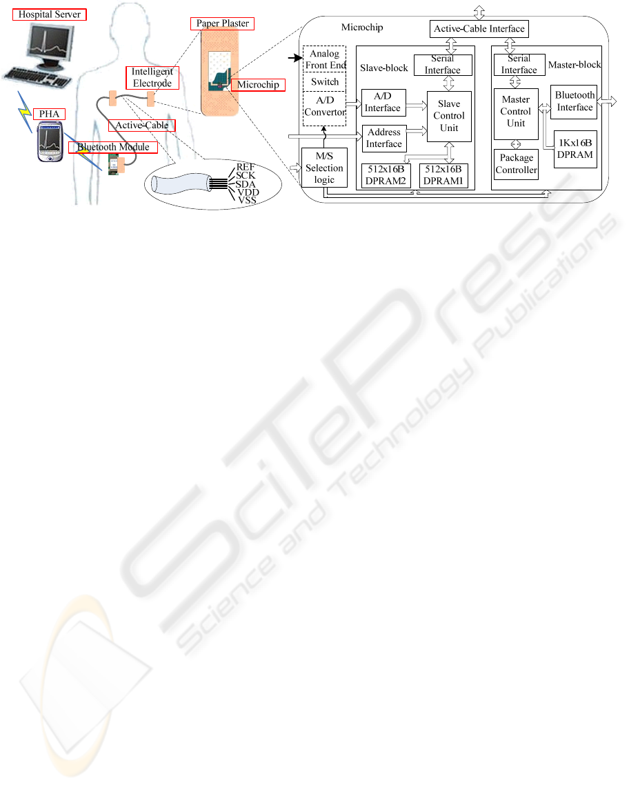
(a) (b)
Figure 1: Block diagram of the device.
2 FUNCTIONAL DESCRIPTION
The block diagram in Figure 1 shows the ASIC
structure. In this system, three intelligent electrodes
are connected serially by the Active-Cable.
Biological potential differences between specific
electrodes applied on the patient’s skin are captured,
pre-processed and digitized directly on the
intelligent electrodes. These obtained signals are
collected via the Active-Cable and finally
transmitted to a hand-held personal health assistant
(PHA) using IEEE 802.11b standard by a Bluetooth
module (Tejero-Calado et al. 2005). Upon the
patient’s need, the PHA can process the data, display
the ECG waveforms and other parameters on its
LCD screen as a real-time feedback. In addition, the
data can be stored in a local non-volatile memory
card for a further diagnosis. If required, the data can
be sent to the hospital server via GPRS
communication networks (Rasid and Woodward
2005). In the following parts of this paper, we will
describe the principle and the methodology of the
intelligent electrode in details.
2.1 ECG Signal Acquisitions Overview
The signal from the electrode is an analog signal
with low amplitude ranging from 0.1 mV to 5 mV.
The bandwidth of the ECG signal is only 250 Hz.
The electrodes which are positioned on the skin
could generate a polarization voltage of several 100
mV. The amplifiers, which gain the electrode
signals, have to be controlled if the voltage reaches
their limits. A high energy defibrillation impulse of
4.5 kV applied to the patient’s chest should not
destroy the IC.
According to the functionality shown in Figure
1b, the ECG chip could be divided into analog part
and digital part. The analog part performs the
functions of ECG signal capturing, amplification,
filtering, conditioning, and consequently digitizing
with an integrated 16-bit Delta-Sigma A/D converter
at a sample rate of 1000 samples per second. The
digital part carries out the tasks of digital signal
filtering (Lian and Yu 2005), ECG data store and
transmission.
In order to have an easy functional verification,
we prefer to tape out the analog part and the digital
part individually. The analog part is implemented
and verified on another chip. In this paper, we only
discuss the digital part of the ECG chip.
2.2 Reconfigurable ASIC
As shown in Figure 1b, each microchip mainly
consists of three blocks: Master-block, Slave-block
and M/S Selection Logic. There are two working
modes available for each intelligent electrode.
According to the system definition, each intelligent
electrode can be configured either as a Master-
electrode or a Slave-electrode by the M/S Selection
Logic module. The Master-block works when the
intelligent electrode is configured as a Master-
electrode, otherwise this block keeps at an idle state
to minimize the power consumption. The same
circumstance applies to the Slave-block.
Different from the traditional ECG signal
sampling approach, where the electrode works only
as an electric conductor suffering from many kinds
of noise, in this design, the ECG signal is directly
captured and digitized inside the Slave-electrode
with minimal noise interference. The function of
BIODEVICES 2009 - International Conference on Biomedical Electronics and Devices
210

Slave-block is to obtain the digitized ECG signal
through A/D interface and store them into an on-
chip DPRAM temporarily. As illustrated in Figure
1b, each Slave-electrode has two pieces of built-in
DPRAMs with 512 words each. At any given time,
one DPRAM is used for the write operation (save
the ECG data); the other DPRAM is used for the
read operation (transmit the ECG data). The finite
state machine (FSM) running on the Slave-block
could guarantee that the ECG data stored in one
DPRAM would be read out before being overwritten
by the upcoming ECG data.
In this system, the intelligent electrode placed on
the patient’s lower-belly is assigned as the Master-
electrode, which is connected with the other two
Slave-electrodes serially by the Active-Cable. The
Master-electrode takes charge of the whole ECG
monitoring system. The FSM running inside
Package Controller can issue a series of commands
according to the specific system status stored in
local registers. By generating these commands, the
Master-electrode is able to collect ECG data from a
target Slave-electrode, or check the current status of
a certain Slave-electrode. Compared with a Slave-
electrode, a Master-electrode has a larger DPRAM,
because it has to provide enough memory space for
the ECG data from all Slave-electrodes for an
interval of half a second. ECG data collection
process is initiated by the Master-electrode with a
time interval of half a second. During this collection
process, all ECG data stored inside a certain Slave-
electrode will be transferred to the Master-electrode
via the Active-Cable. Finally, all collected ECG data
will be sent to the PHA by the Bluetooth module.
2.3 Active-cable Architecture
All ECG data and command packages are
transmitted over the Active-Cable which is an
indispensable part of this wearable ECG monitoring
system. As illustrated in Figure 1a, it is a thin, soft
and dedicated cable composed of five metal wires,
which are named REF, SCK, SDA, VDD and VSS,
respectively.
REF is an analog reference signal used for A/D
conversions on all Slave-electrodes. ECG data are
obtained by digitizing the electric potential
difference between a local measurement point and
the REF signal. In this design, by controlling a
switch embedded inside Analog Front End block,
the Master-electrode provides its local electric
potential as the system REF signal. The ECG data
transmission reliability is guaranteed by using a 2-
wire bus which is composed of SCK and SDA in the
Active-Cable. SCK carries the serial clock, while
SDA transmits commands and digital ECG data. The
ECG data are transmitted at a bit rate of 0.9 Mbits/S.
The last two wires in the Active-Cable are VDD and
VSS providing 3.3V system power and digital
ground respectively. In order to minimize the
electrical interference induced by neighbouring
wires and achieve high-quality ECG data, REF is
properly shielded with metal foil.
2.4 Slave-chain Scan Process and ECG
Data Collection Methodology
When the system is powered up, the Master-
electrode should know the exact addresses of Slave-
electrodes active in this system. In the current
design, a unique four-bit vector is assigned to each
Slave-electrode as its address.
In order to get a thorough knowledge of the
whole system, the Master-electrode initiates a slave-
chain scan process after power up, shown in Figure
2. All Slave-electrodes that are connected to the
Active-Cable will be scanned during this process.
The Master-electrode sends out a command frame
containing the target Slave-electrode address to the
Active-Cable. Simultaneously, a built-in timer starts
up. An acknowledgement will be sent back to the
Master-electrode if the target Slave-electrode exists.
Subsequently, this target address is saved into the
address-table, meaning that this Slave-electrode is
online and the Master-electrode will talk to it later.
Figure 2: Slave-chain scan process.
AN ASIC SOLUTION FOR INTELLIGENT ELECTRODES AND ACTIVE-CABLE USDED IN A EARABLE ECG
MONITORING SYSTEM
211
Otherwise, there will be no acknowledgement if the
target Slave-electrode does not exist. When the timer
overflows, the Master-electrode asserts that this
Slave-electrode does not exist in the system. It will
try the next Slave-electrode address until the last
Slave-electrode is reached and Slave-chain scan
process stops here.
To analyse the ECG signals, it is important that
they should be stored simultaneously (
Desel et al.
1996
). In this design, all A/D converters located
inside Slave-electrodes would not start up until the
Synchronous Sampling Command is issued by the
Master-electrode. In other words, this broadcast
command makes synchronous A/D conversions start
to sample skin electrical potential simultaneously.
During the ECG data transmission, time division
multiplexing mode is employed. The Master-
electrode initiates this process every half second,
and visits all Slave-electrodes in a serial way with
one time slot each.
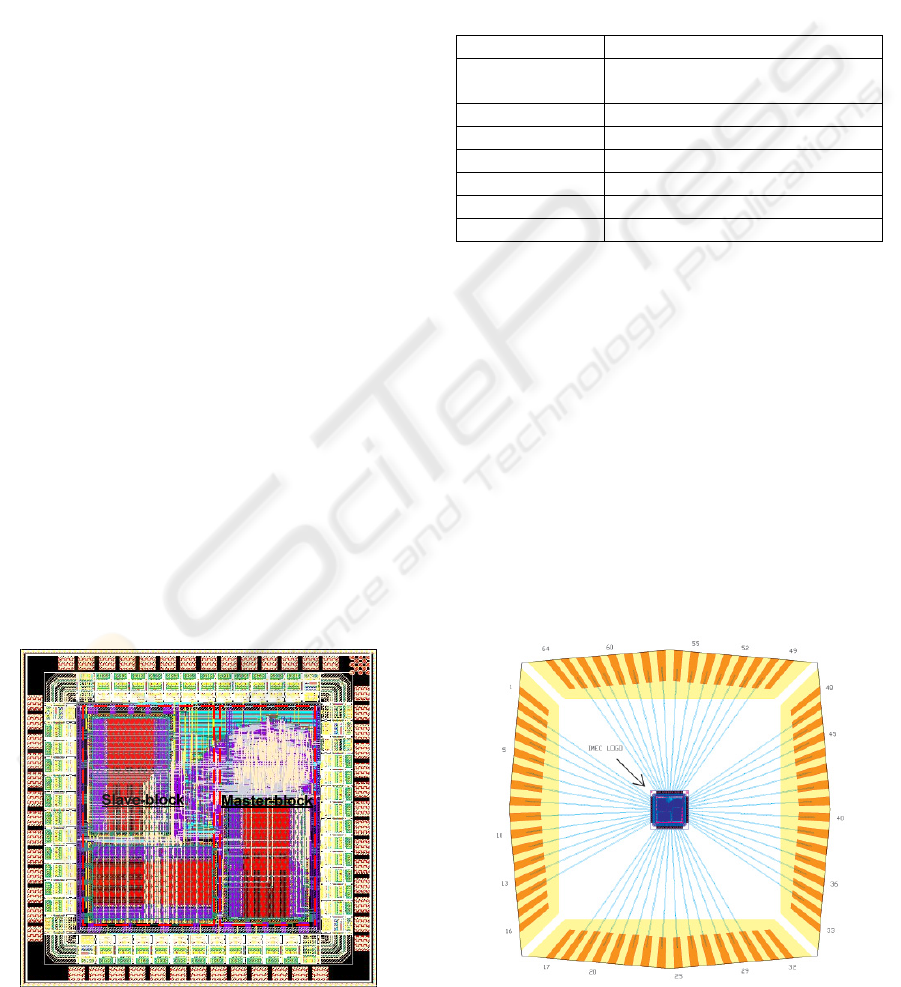
3 LAYOUT AND RESULTS
The embedded microchip is implemented using a
standard 0.18
μ
m cell library for UMC 0.18
μ
m
Mixed-Mode and RF_CMOS process. A photograph
of the ASIC is shown in Figure 3. The Slave-block
is located on the left side; the Master-block is on the
right side. The chip summary is shown in Table 1.
The microchip has a core area of 1000
μ
m ×
1000
μ
m and a die size of 1525
μ
m × 1525
μ
m. It
consists of 121,514 gates excluding memories and
operates at a clock frequency of 24 MHz. The total
number of I/O pins is 54. And hence, a 64-pin CQFP
package is adopted for this design. The package
bonding diagram is shown in Figure 4. Even though
Figure 3: Photography of the ASIC.
the estimated dynamic power dissipation is 857
μ
W
with cell leakage power of 6
μ
W excluding the
power consumption of memories, the actual power
consumption would be far less than this estimated
value because the microchip consumes much less
when it stays at the idle state. The I/O cell power
supply is 3.3 V and the core circuit power supply is
1.8 V. The I/O cell power supply is splitted into 3 ×
2 different power ports to suppress crosstalk.
Table 1: Embedded microchip summary.
Microchip Summary
Technology UMC 0.18
μ
m Mixed-Mode and
RF_CMOS. 1.8 V core, 3.3 V I/O
Die size 1525
μ
m × 1525
μ
m
I/O pin number 54
Package 64-pin CQFP
Gate count 121,514
Clock 24 MHz
Dynamic power 857
μ
W
4 CONCLUSIONS
In this paper, we present a novel ASIC architecture
for the intelligent electrode. The chip is taped out
using a standard 0.18
μ
m CMOS process with an
area about 2.3 mm
2
. The post-layout simulation
result shows that this proposed microchip is featured
by ultra low power consumption, high sample rate
and high ECG data resolution. It is quite feasible for
the battery powered long term ECG monitoring and
analysis system. This intelligent electrodes based
wearable ECG monitoring system is capable of
capturing, pre-processing and digitizing of two
analog signals simultaneously. This system has also
Figure 4: Package bonding diagram.
BIODEVICES 2009 - International Conference on Biomedical Electronics and Devices
212

the capability of polling and digitizing analog
signals from additional twelve intelligent electrodes
for a more complicated ECG study.
In the next release of this ASIC design, the
number and size of Dual Port Memories will be
optimized. A switched DPRAM structure will be
adopted to make more chip area for other enhanced
functionalities. Moreover, the analog front end and
A/D converter will be integrated in the next tape out.
ACKNOWLEDGEMENTS
The authors would like to thank iPack Centre at
Royal Institute of Technology, Sweden, who
supports the above project. We would also like to
thank Ms. Zhangwei Yu for her comments.
REFERENCES
Desel, T., Reichel, T., Rudischhauser, S., Hauer, H., 1996.
A CMOS nice channel ECG measurement IC. In 2nd
International Conference on ASIC.
Dong, J., Zhang, S., and Jia, X., 2008. A portable
intelligent ECG monitor based on wireless internet and
embedded system technology. In International
Conference on BioMedical Engineering and
Informatics.
Hung, K., Zhang, Y.T., and Tai, B., 2004. Wearable
medical devices for tele-home healthcare. In 26th Ann.
International Conf. of the Engineering in Medicine
and Biology Society, IEEE-EMBS.
Lian, Y., and Yu, J., 2005. A low power linear phase
digital FIR filter for wearable ECG devices. In 27th
Ann. International Conf. of the Engineering in
Medicine and Biology Society, IEEE-EMBS.
Rasid, M. and Woodward, B., 2005. Bluetooth
telemedicine processor for multichannel biomedical
signal transmission via mo-bile cellular networks. In
IEEE Transactions on Information Technology in
Biomedicine, vol.9, no.1 pp.35–43.
Tejero-Calado, J., Lopez-Casado, C., Bernal-Martin, A.,
Lopez-Gomez, M., Romero-Romero, M., Quesada, G.,
Lorca, J., and Rivas, R., 2005. IEEE 802.11 ECG
monitoring system. In 27th Annual International
Conference of the Engineering in Medicine and
Biology Society, IEEE-EMBS.
Yang, G., Chen, J., Cao, Y., Hannu, T., and Zheng, L-R.,
2008. A Novel Wearable ECG Monitoring System
Based on Active-Cable and Intelligent Electrodes. In
IEEE Proc of 10th International Conference on e-
Health Networking, Applications and Services,
Singapore.
AN ASIC SOLUTION FOR INTELLIGENT ELECTRODES AND ACTIVE-CABLE USDED IN A EARABLE ECG
MONITORING SYSTEM
213
