
MULTIPHASE DEPLOYMENT MODELS FOR FAST SELF
HEALING IN WIRELESS SENSOR NETWORKS
Omer Zekvan Yilmaz, Albert Levi and Erkay Savas
Faculty of Engineering and Natural Sciences, Sabanci University, Istanbul, Turkey
Keywords:
Key Management, Random Key Predistribution, Sensor Networks.
Abstract:
The majority of studies on security in resource limited wireless sensor networks (WSN) focus on finding
an efficient balance among energy consumption, computational speed and memory usage. Besides these
resources, time is a relatively immature aspect that can be considered in system design and performance
evaluations. In a recent study(Castelluccia and Spognardi, 2007), the time dimension is used to lower the ratio
of compromised links, thus, improving resiliency in key distribution in WSNs. This is achieved by making
the old and possibly compromised keys useful only for a limited amount of time. In this way, the effect of
compromised keys diminish in time, so the WSN selfheals. In this study we further manipulate the time
dimension and propose a deployment model that speeds up the resilience improvement process with a tradeoff
between connectivity and resiliency. In our method, self healing speeds up by introducing nodes that belong to
future generations in the time scale. In this way, the duration that the adversary can make use of compromised
keys become smaller.
1 INTRODUCTION
The significance of wireless sensor networks (WSNs)
is that the cheapest possible node model is targeted
due to nature of the network; such as being in a hostile
environment, unattended, and due to the geographic
constraints which prevent reusability of a sensor node.
Moreover, the application fields of WSNs, like battle-
field surveillance and habitat monitoring need secu-
rity precautions in order to work as intended (Akyildiz
et al., 2002).
For secure communication in WSNs, the symmet-
ric encryption is preferred for the sake of energy con-
sumption and faster processing. For this purpose, the
distribution of symmetric keys is obligatory and its
difficulty is the main problem of secure communica-
tion in WSNs.
Thinking of the very intuitive but inefficient
scheme where all possible pairwise keys in the net-
work are kept in the memory of each node, the con-
nectivity is at its utmost. However, the extra memory
that is wasted for unused keys, is too expensive for a
tiny sensor node.
On the other hand, using a single key in the whole
network will be the most desired choice for memory.
However, all the links will be compromised if the key
is captured by adversary.
Therefore, a viable solution would look for an
equilibrium in resource consumption in order to deal
with the strict constraints. In this sense, Eschenauer
and Gligor (Eschenauer and Gligor, 2002) devise a
mechanism in which all nodes are given a random
amount of keys from the key pool. This scheme
results in reasonable levels of connectivity and re-
siliency.
Besides the advantage of randomness, the time di-
mension is a reality for any network and should be
considered in the design. Castelluccia and Spognardi
proposed RoK (A Robust Key Pre-distribution Pro-
tocol for Multi-Phase WSNs)(Castelluccia and Spog-
nardi, 2007), that takes time dimension into account.
In RoK (Castelluccia and Spognardi, 2007), the net-
work lifetime is divided into phases. At the end of
each phase, all the keys of nodes are updated. Thus,
new links are established with updated keys that are
out of the reach of adversary before compromising
nodes with new keys.
In this study, we improve the resiliency of RoK
by further exploiting the time dimension. Our contri-
bution is to use keys that are assigned to future uses,
earlier than their times. As a result, we end up with
improved resiliency measures. As explained in Sec-
tion III, we propose two models called Constant Off-
set Future Random Generations (COFRG) and Grow-
136
Zekvan Yilmaz O., Levi A. and Savas E. (2008).
MULTIPHASE DEPLOYMENT MODELS FOR FAST SELF HEALING IN WIRELESS SENSOR NETWORKS.
In Proceedings of the International Conference on Security and Cryptography, pages 136-144
DOI: 10.5220/0001924301360144
Copyright
c
SciTePress

ing Offset Future Random Generations (GOFRG). At
each deployment phase, both of them choose a time
interval in future. Some of the keys from this time
interval are chosen randomly and used in the current
time. In COFRG, the time interval is a fixed offset
from current time. However, in GOFRG this interval
has growing offsets with respect to present. In this
way, at each deployment of GOFRG, a high fraction
of deployed keys become new to adversary. This is
valid for COFRG too, but the fraction of new keys at
each deployment of COFRG becomes lower after the
initial stages of the network. Therefore, the contribu-
tion of GOFRG to resiliency is better as compared to
COFRG. On the other hand, connectivity decreases in
both models due to higher number of nodes that be-
long to future generations in comparison to RoK.
The rest of the paper includes the background in-
formation on Multi-Phase Keying in Section II. In
Section III the proposed schemes are presented. The
advantages versus the drawbacks of the schemes are
discussed in Section IV. Related works are described
in Section V. Finally Section VI summarizes the con-
clusions.
2 PREVIOUS WORK IN
MULTI-PHASE KEYING
In Multi − Phase Keying models, the network life is
divided into phases of equal time intervals. All the
keys in the key pool and in the key rings of nodes are
updated with each phase, such that the adversary fails
to derive the keys of future phases from previously
captured keys. At the same time, deriving keys of
previous phases from current phase keys is prevented.
However for the sake of connectivity among nodes
that are active in neighboring phases, this prevention
mechanism is activated gradually, as explained be-
low. All the schemes that are discussed in this paper,
namely RoK, COFRG and GOFRG are different vari-
ations of the mul ti − phase approach.
Each phase is called a generation which consists
of 10 rounds, where one round is the smallest unit of
time. The reason for this time segmentation is that the
attack scenarios are based on rounds.
In RoK (Castelluccia and Spognardi, 2007) all the
keys are identified with the generation in which they
are used. So that, by the end of each generation all
the valid keys are updated. However, in order to com-
promise the maximum number of links, an attacker
may prefer to update the key ring of each captured
node forever. To prevent this, a security mechanism
should be able to guarantee that the key ring of any
node is bound to a given amount of time. After ex-
ceeding this time, a node should no more establish a
secure communication between new deployed nodes.
In RoK (Castelluccia and Spognardi, 2007) this time
duration is set to 10 generations, which is almost the
maximum battery life of a node. This binding is pro-
vided by the backward and forward hash chains.
As a result of this binding, the keys obtained from
captured nodes get old by time and new established
links remain safe. This decreases the ratio of com-
promised links with every generation, if adversary
stops capturing new nodes. The decrease in this ra-
tio, i.e. the improvement in resiliency, is also called
the sel f − healing of the network.
2.1 Node Configuration Phase
At the beginning of each generation, a set of sensor
nodes are deployed with forward and backward key
rings. These key rings are hashed at the end of each
generation, so that the new key rings are identified
with the new generation. This way nodes maintain
their lives among generations. In this scheme, for-
ward and backward hash chains, constitute the up-
date mechanism mentioned above, satisfying its secu-
rity requirements thanks to the irreversibility of hash
functions.
Each element of the forward and backward hash
chains will be referred as a Forward K ey or Backward
Key. The key rings are sets containing a number of
chosen Forward Keys and Backward Keys from the
pools, called Forward Key Pool and Backward Key
Pool. The Forward Key Pool, at Generation 0, i.e.
the first deployment of the network, is defined as fol-
lows. Please refer to Table 1 for the definitions of
symbols:
FKP
0
= f k
0
1
, f k
0
2
,..., f k
0
P/2
, (1)
where each f k
0
i
is randomly generated.
At Generation j + 1, the f orward keys are re-
freshed as follows:
f k
j+1
t
= H
0
( f k
j
t
), (2)
FKP
j+1
= f k
j+1
1
, f k
j+1
2
,..., f k
j+1
P/2
(3)
The Backward Key Pool, is first generated for
Generation n, i.e. the last generation of the network.
The backward keys at Generation n, are initialized
with random values:
BKP
n
= bk
n
1
,bk
n
2
,...,bk
n
P/2
. (4)
At Generation j, the backward keys are refreshed
as follows:
MULTIPHASE DEPLOYMENT MODELS FOR FAST SELF HEALING IN WIRELESS SENSOR NETWORKS
137

Table 1: Symbols Used in Multi-Phase Keying.
P Key Pool Size
m Key Ring Size
FKP Forward Key Pool
BKP Backward Key Pool
fk Forward Key
bk Backward Key
g
X
The generation of node X
X
j
i
Item X with Generation j and index i
LT Life Time of the key ring of a node.
H’, H” Two different hash functions.
f k
j
i
-bk
j
i
A forward-backward key pair.
bk
j
t
= H
0
(bk
j+1
t
), (5)
BKP
j
= bk
j
1
,bk
j
2
,...,bk
j
P/2
(6)
Therefore, at Generation j + 1 the backward key
pool is defined as:
BKP
j+1
= bk
j+1
1
,bk
j+1
2
,...,bk
j+1
P/2
, (7)
Every node is configured with f orward and
backward keys in the following way: For a node with
ID
A
and generation g
A
, the i
th
key of the Forward Key
Ring is the key from the Forward Key Pool of index
H
00
(ID
A
||i||g
A
). This is done for all m/2 keys in the
Forward Key Ring. For the Backward Key Ring the
same operation is performed using the indices of the
Backward Key Pool.
2.2 Key Establishment Phase
After deployment, a node A broadcasts ID
A
and its
generation, g
A
. A receiver node B, at first, decides
if their generations are close enough or not. This is
done by testing if |g
A
− g
B
| < LT. In addition to this,
if g
A
< g
B
and the above holds, then, they can share
keys starting from Generation g
B
up to Generation
“g
A
+ LT − 1”.
Secondly, Node B calculates H
00
(ID
A
||i||g
A
) and
compares them with its indices, H
00
(ID
B
|| j||g
B
) for
all i, j ∈ 1, 2, m/2. If there are collisions such that
H
00
(ID
A
||x||g
A
) = H
00
(ID
B
||y||g
B
), (8)
where x, y ∈ 1, 2...m/2, then, it is known that they both
have the forward key f k
g
B
H
00
(ID
B
||y||g
B
)
and the backward
key bk
g
A
+LT−1
H
00
(ID
B
||y||g
B
)
in their memory. This way, all col-
luding local indices a, b, z ∈ 1,2...m/2 are found and
the following becomes their pairwise symmetric key:
K = H
0
( f k
g
B
H
00
(ID
B
||a||g
B
)
||bk
g
A
+LT−1
H
00
(ID
B
||a||g
B
)
||...|| (9)
f k
g
B
H
00
(ID
B
||z||g
B
)
||bk
g
A
+LT−1
H
00
(ID
B
||z||g
B
)
)
Any attacker needs all these f orward and back-
ward keys to compromise this pairwise key. These
keys can not be reached using a particular f orward −
backward key pair. A f orward key is reachable
only through a suitable past f orward key and a
backward key is reachable only through a suitable fu-
ture backward key; these suitable keys need to have
the same indices with the keys in 9. Therefore, an
adversary would construct a table that is filled with
the hash chains of the captured keys. This way future
f orward keys and past backward keys can be calcu-
lated using the hash function as in 2 and 5.
3 PROPOSED SCHEMES
The hashing mechanism in RoK (Castelluccia and
Spognardi, 2007) and its usage of time dimension
through generations provide the sel f healing ability
of the network. In our study, we modify the node
deployment model of RoK by using nodes of future
generations. Therefore the network acts as if it has
the state of a few generations later, which results in a
faster sel f healing process.
In this study, we propose to use nodes that belong
to a random future generation, at each deployment.
This method will be referred as Future Random
Generations. Two different models on how to choose
from future generations are proposed as explained be-
low. In the classical RoK approach, the attacker is
able to compromise keys of established links provided
that the captured nodes and the link that is to be cap-
tured have overlapping generations. In the proposed
models, we enable a faster sel f healing and improve
resiliency by reducing the probability of overlapping
generations via future random generations.
At the end of each generation, some of the nodes
including the newly deployed ones have key rings that
belong to a few generations ahead. In this way, each
node in the network happen to live in a different gen-
eration than most of its neighbors. Therefore, this
can be referred as a generation mixture or traveling
in time.
The early deployment of Future Random
Generations would cause a decrease in connectivity.
Actually our method creates a tradeoff between
resiliency and connectivity, which is analyzed in
Section IV.
3.1 Deployment Models
In RoK (Castelluccia and Spognardi, 2007) at each
generation, the new nodes that are deployed over the
SECRYPT 2008 - International Conference on Security and Cryptography
138
field are chosen such that they belong to current gen-
eration. However in our schemes, the generations of
the new nodes are chosen randomly. The range of
generations from which the generation of each new
node is randomly selected is defined as deployment
window. The position of the deployment window
on the time scale shifts towards future at each gen-
eration. The rules of shifting the deployment win-
dow constitute our deployment models. We propose
two such models, namely COFRG (Constant Offset
Future Random Generations) and GOFRG (Growing
Offset Future Random Generations), that are detailed
in the following subsections. In both models, the size
of the deployment window is fixed to 10 generations.
In our models, each new node is assigned a uni-
formly random generation picked out of the current
deployment window.
3.1.1 Constant Offset Future Random
Generations (COFRG)
In COFRG, the deployment window has a constant
offset to current generation. The deployment window
shifts one by one at each generation. In this way, the
offset between the deployment window and the cur-
rent generation remains unchanged.
In COFRG, the network is initialized without con-
sidering the deployment window rules and all the
nodes are deployed as Generation 0 nodes. How-
ever, all nodes to be deployed after Gener ation 0 have
generations randomly selected out of deployment
window.
The discrete uniform random variable that deter-
mines the generation of a specific node, G
COFRG
, is
defined as follows.
G
COFRG
=
0 if T = 0
T + D +X if T > 0
where X is a random integer uniformly distributed in
{0,1,...,9}, T is the index of current generation and
D is the offset to current generation.
At Generation T , the deployment window covers
the range T + D to T + D +9. The generation of each
node to be deployed is a uniform random variable,
G
COFRG
, picked out of this deployment window. In
the next generation, T + 1, the deployment window
is shifted one step forward having the range T + 1 +
D to T + 1 + D + 9. The generation of all nodes to
be deployed at T + 1 is selected randomly from this
deployment window. This goes on for all consecutive
generations.
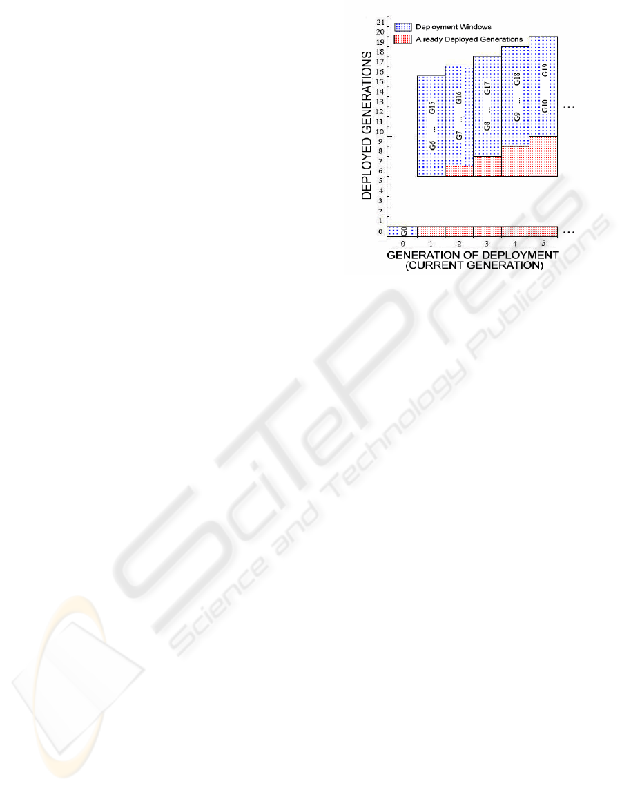
Fig. 1 exemplifies both deployment window and
the existing generations on the field in COFRG with
Figure 1: Deployed Generations vs. Generations of Deploy-
ment in COFRG with D=5.
D = 5. Each cell with dotted background is a deploy-
ment window and the symbols in these cells represent
the range of generations in that deployment window.
The horizontal axis shows the current generation. For
an example, the deployment range of Generation 4
is between the generations 9 and 18 (inclusive). A
node that is to be deployed in the current genera-
tion is assigned a future random generation out of the
deployment window that corresponds to this current
generation.
The vertical axis is a reference to observe the ex-
isting generations on the field. In addition to dotted
background that corresponds to deployment window
of current generation, the generations with red grid
texture show the ones that have been deployed prior
to current generation. For example, the deployed gen-
erations at the time of Generation 3 are Generation 0
and the generations between 6 and 17.
The generations between 1 and 5 are never de-
ployed in any generation. This is due to the constant
offset feature of COFRG.
3.1.2 Growing Offset Future Random
Generations (GOFRG)
In GOFRG, the deployment window shifts towards
future with some jumps. Each node is assigned a gen-
eration which is determined by a discrete uniform ran-
dom variable, G
GOFRG
, as follows.
G
GOFRG
=
0 if T = 0
(T − 1) ∗ JUMP + T + X if T > 0
where X is a random integer uniformly distributed in
MULTIPHASE DEPLOYMENT MODELS FOR FAST SELF HEALING IN WIRELESS SENSOR NETWORKS
139
{0,1,...,9}, T is the index of current generation and
JUMP is the length of additional offset.
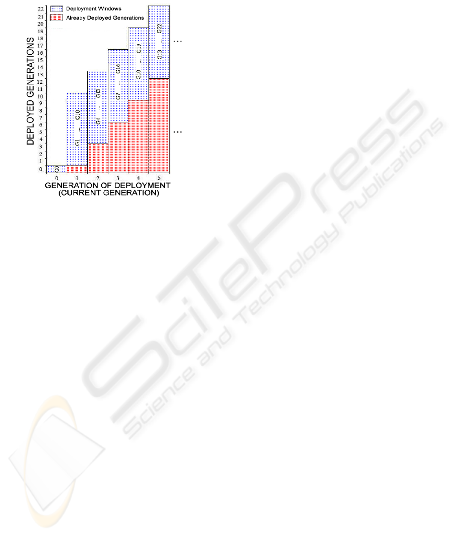
Figure 2: Deployed Generations vs. Generations of Deploy-
ment in GOFRG.
Besides the natural increase in the time scale (one by
one), the deployment window in GOFRG makes ad-
ditional shifts with the length of JUMP at each gen-
eration. Hence, a deployment window of GOFRG in-
creases its offset to current generation with constant
speed. The JUMP parameter is constant for a given
GOFRG model.
Fig. 2 illustrates the deployment windows and
existing generations upto the fifth generation of the
network in GOFRG with JUMP=2. The deployment
range at Generation 3 is between 7 and 16. In this
case the deployment has an offset of 4 to the current
time. The following generation (Generation 4) has
the deployment window with range 10 to 19, which
has an offset of 6 to the current generation. In this
way, the difference between the deployment window
and current generation increases as generations go by.
For each deployment in both COFRG and
GOFRG, the links established using generations that
are deployed for the first time cannot be compromised
using the nodes captured in previous generations. The
number of these safe generations is (JUMP + 1)/10
of the length of the deployment window. This ratio is
1/10 in COFRG, considering that JUMP = 0. There-
fore, as compared to COFRG, higher fraction of gen-
erations are out of the reach of adversary in GOFRG.
This difference leads to higher resiliency values for
GOFRG as will be discussed in 3.3.
In COFRG scheme, the offset is kept constant in
order not to be too far from current generation. Con-
sequently, connectivity is kept within reasonable lev-
els. However, this balance between offset and con-
nectivity is not taken into consideration in GOFRG
for the sake of better resiliency.
3.2 Key Establishment Phase
The key establishment phases of both models COFRG
and GOFRG are identical with RoK, however the re-
sults are different as explained in 3.3. The generation
overlaps in COFRG and GOFRG are fewer compared
to RoK. The reason is that, the deployment genera-
tions are mostly chosen from future time domains, so
the generation overlap probabilities between the key
rings of nodes are reduced. Therefore, less node pairs
are able to establish shared keys, however, the result-
ing key becomes more resilient in GOFRG than RoK,
as explained in 3.3.
As in most of the WSN applications, whenever
two neighboring nodes are not able to establish a pair-
wise key using the key rings in their memories, they
apply path key establishment procedure in order to
communicate in a secure way. The path key estab-
lishment phase has the following steps:
1. One of the nodes broadcasts a message that con-
tains the IDs of the two nodes in question, looking
for an anchor node that shares a key with both of
the nodes.
2. This broadcast is flooded across the network until
it reaches an anchor. This step will increase the
communication overhead of the nodes involved.
Therefore the broadcast is allowed to make at
most, say, 3 hops.
3. The anchor node generates a random pairwise key
for the two nodes and sends it to both parties using
the secure channels established earlier.
The path key establishment is supposed to keep
the connectivity in COFRG and GOFRG in desired
levels, with a cost of energy consumption due to com-
munication overhead. However, the positive effects of
path key establishment on connectivity are not shown
in the figures below in order to observe the connectiv-
ity prior to path key establishments.
3.3 Performance Evaluation
RoK scheme (Castelluccia and Spognardi, 2007) ex-
plains in detail how Multi − Phase Keying mecha-
nism improves resilience over time. This behavior is
called the self healing ability of the network, which
addresses the decrease of adversary ability to com-
promise new links with a given number of captured
nodes. As a result the fraction of compromised active
links used in the network decreases.
SECRYPT 2008 - International Conference on Security and Cryptography
140
Since our goal is to speed up the sel f healing
process and observe the resulting resiliency and con-
nectivity metrics, by employing the proposed Future
Random Generations approach, the detailed compar-
ison between previous schemes which was done in
(Castelluccia and Spognardi, 2007), is not repeated
in this paper.
3.3.1 Simulation Details and Performance
Metrics
The simulations were implemented in C# .Net 2005
on Windows XP SP2. Each simulation was run 20
times for the sake of accuracy. COFRG and GOFRG
schemes were tested together with RoK. For simplic-
ity 20*20 area is used to deploy 400 nodes. With ver-
tical and horizontal neighboring, each node has ex-
actly 4 neighbors.
1
At the end of each generation, the nodes that run
out of battery are replaced with new nodes, which
are configured according to the rules of the related
scheme. This replacement obviously is not feasible in
real life but to cope and compare the results with RoK
scheme, a similar deployment is adopted.
For all scenarios, the sizes of both f orward and
backward pools are 100.000 and the sizes of f orward
and backward rings of a node are both 100.
The lifetimes of nodes are decided according to
Gaussian distribution with mean 5 and standard devi-
ation 10/6.
The simulations were run with two attacker mod-
els: In the first group, the attacker, called the constant
attacker, captures 5 nodes per round. In the second,
the attacker, called the temporary attacker, captures
nodes only until the end of Generation 9, again with
a rate of 5 nodes per round.
The figures below show two kinds of mea-
surements, the compromise ratio and the local
connectivity for all the models RoK, COFRG and
GOFRG. For the calculation of the compromise ra-
tio, all links that are compromised by adversary
are counted except the links that belong to captured
nodes. This count is divided by the total of all links
that belong to non captured nodes. In addition, this ra-
tio was calculated separately for active and total com-
promised links in order to differentiate between the
compromise of active and dead links. Noting that the
compromise ratio is the inverse of resiliency metric
and the drop in compromise ratio implies the increase
in resiliency and visa versa. Here a dead link refers
to a link which has at least one of its end nodes has
1
These parameters are kept the same as (Castelluccia
and Spognardi, 2007).
gone out of battery. An active link is visa versa, i.e.
both of its ends have enough battery to communicate.
For local connectivity, the key establishment re-
quests between neighboring nodes are counted. In
these key establishment attempts, the number of suc-
cessful ones that end up with valid key establishments
were divided into the total of all the attempts. The re-
sult show the amount of success of the related scheme
in terms of local connectivity. Despite that low con-
nectivity is supported by path key establishments, this
support is not reflected the graphs below in order to
observe the connectivity performances of all schemes.
3.3.2 Simulation Results
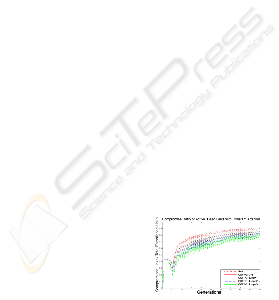
Fig. 3 shows the number of all compromised links
over all the links established since the beginning of
the network versus generations, with the constant at-
tacker model. Here, at the early stages of the net-
work the adversary is able to benefit from the cap-
tured nodes and increase the compromise ratio im-
mediately, which is due the majority of Generation
0 nodes in the area. After this early dramatic increase
until around Generation 5, all the schemes change
their behavior. The reason is that by Generation 5
the majority of the nodes scattered in Generation 0
are out of battery and replaced by new nodes. In this
way, all the schemes start to follow a steady behavior.
At the beginning of the network, all schemes record
above 0.4 compromise ratios. After that, a signifi-
cant drop in compromise ratio, implying the improve
in resiliency, for COFRG and GOFRG schemes can
be seen; where GOFRG with Jump 3 reaches around
0.2 compromise ratio. Finally, the resiliency of all
schemes begin to drop slowly until the end of the net-
work due to the compromise rate of 50 nodes per gen-
eration, despite this, multi − phase approach prevents
the adversary to go beyond 91% of compromise ratio
at worst case.
Figure 3: Compromise Ratio of Dead and Active Links to-
gether, for Constant Attacker Model.
MULTIPHASE DEPLOYMENT MODELS FOR FAST SELF HEALING IN WIRELESS SENSOR NETWORKS
141
In RoK (Castelluccia and Spognardi, 2007), there
is no generation mixture, so at each new deployment
only keys belonging to a single generation are intro-
duced to the network. Therefore, they are certainly
unknown to adversary at the time of deployment. On
the other hand, for each deployment of COFRG, after
the network reaches a steady state by Generation 5,
the generations of the nodes that are deployed contain
already deployed generations with ratio 9/10. In other
words, only 1/10 of the deployed nodes are from gen-
erations that do not exist in the area yet. This causes
high compromise ratios in the latter stages. However
it has around 0.3 compromise ratio at Generation 5
while RoK records 0.45 at that time. This advantage
for the resiliency in COFRG is due to having O f f set
5 from current time and the majority of nodes on the
area being of Generation 0 (see Fig. 1).
The only difference of GOFRG compared to
COFRG is the JUMP parameter which is 0 in COFRG
and has larger values for GOFRG. The performance
of both schemes is similar until Generation 5, where
a significant drop in compromise ratio is achieved. In
order to maintain this performance, at each deploy-
ment, extra jumps towards future is made by GOFRG.
This results in a better resiliency performance than
both of COFRG and RoK throughout the network life.
Meanwhile, using future generations in COFRG
and GOFRG pays off with lower connectivity perfor-
mance (Fig. 4). This is due to the nodes from fu-
ture generations that have lower probabilities of hav-
ing colliding generations with their neighbors com-
pared to RoK. Fig. 1 and Fig. 2 show the generation
diversity at a given time. As it is seen in Fig. 1, with
COFRG at Generation 5 the generations between 0-
19 exist in the network. Therefore it is more difficult
for COFRG nodes to have colliding generations be-
tween their neighbors, according to RoK which has
nearly 10 generations at a given time, considering
the battery lifetimes of nodes. The same applies for
GOFRG, where the diversity of generations causes
loss in connectivity too. In Fig. 2, at Generation 5
there are 22 generations ranging from Generation 0
up to Generation 22. However, the low connectiv-
ity is tolerated with path key establishments which
increase the communication overhead. Despite this
communication overhead, the tradeoff between con-
nectivity and resiliency is desirable since resiliency
has no alternative.
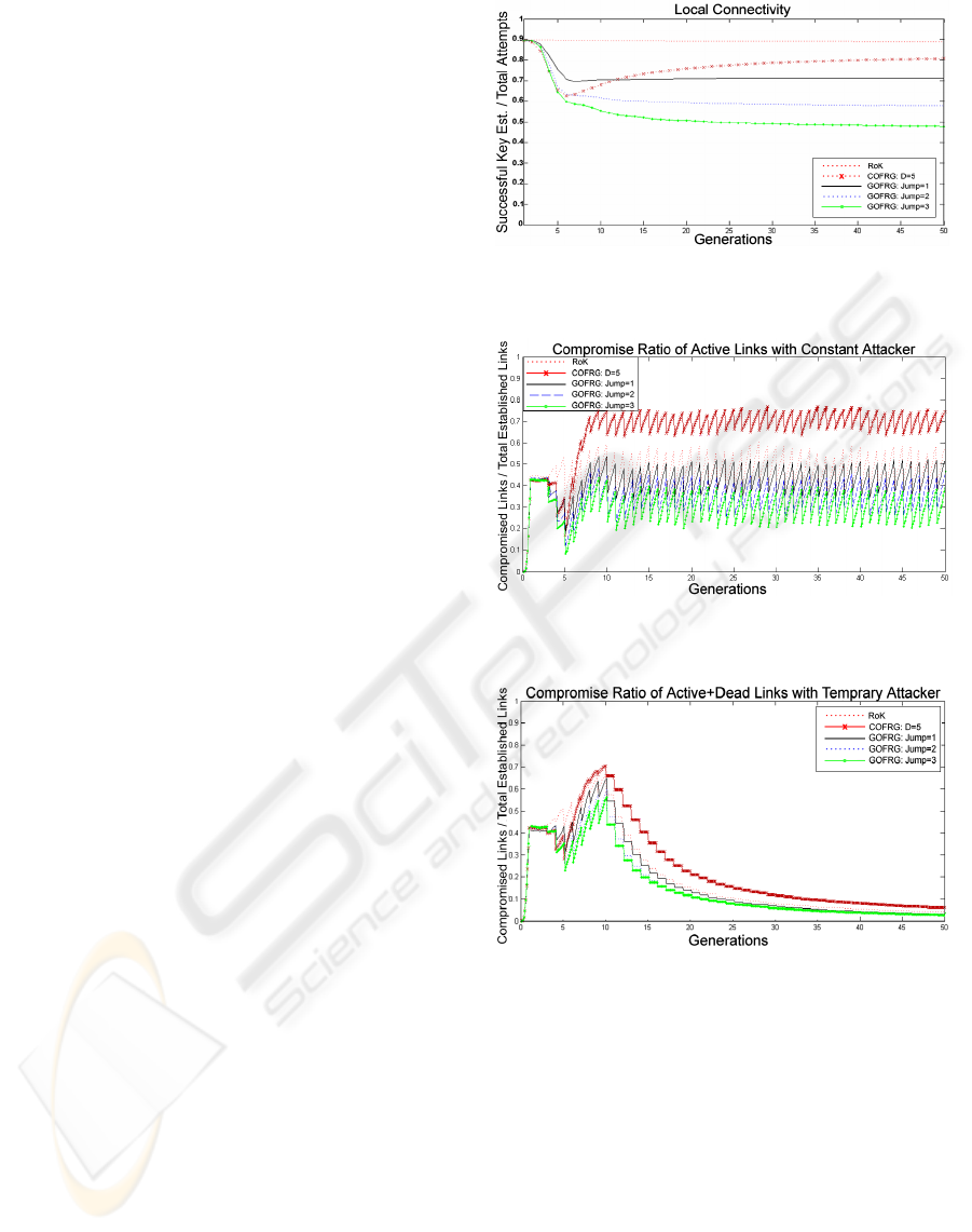
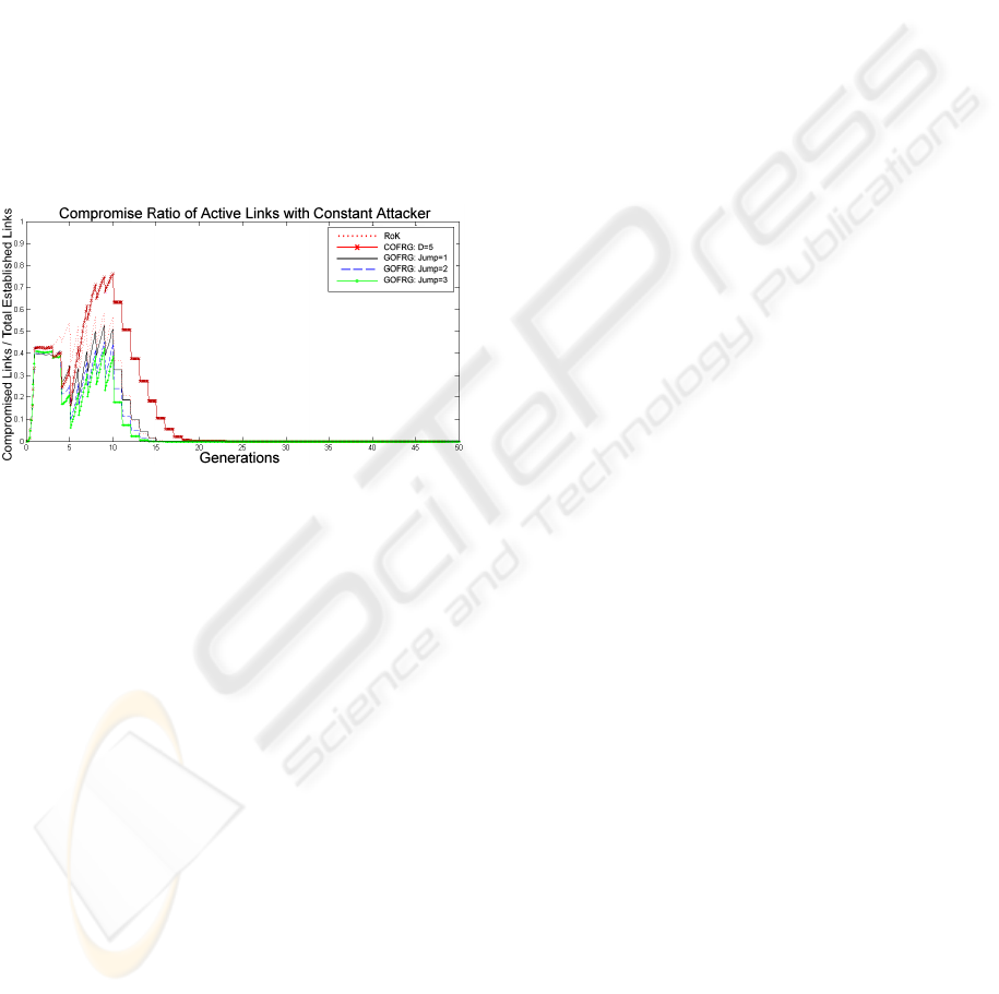
Fig. 5 shows the compromise ratio of active links,
which are certainly more valuable than the dead links
for most of the applications of WSNs. The compro-
mise ratio of all schemes oscillate with certain equi-
librium and do not exceed certain limits, despite the
capture rate of 5 nodes per round. In Fig. 5, the low
Figure 4: Ratio of Successful Key Establishments over all
attempts.
Figure 5: Compromise Ratio of Alive Links, for Constant
Attacker Model.
Figure 6: Compromise Ratio of Dead and Alive Links, for
Temporary Attacker Model.
compromise ratio of GOFRG throughout the whole
network life, compared to RoK and COFRG show
that, its high resiliency values is also valid for active
links. During the steady state of the network, COFRG
is around 0.7 of compromise ratio and RoK oscillates
between 0.55 and 0.4. However, GOFRG perform
better with oscillations between 0.21 and 0.45.
The temporary attacker in Fig. 6, does not com-
promise any nodes after Generation 9. In addition
to that, the adversary can compromise new links un-
til Generation 19 in COFRG, which is the extremum
case. In GOFRG, adversary can not compromise links
after Gener ation 12. Later on, the compromise ratio
SECRYPT 2008 - International Conference on Security and Cryptography
142
that does not reach 0 is due to the dead links at the
hand of adversary that are taken into account in Fig.
6.
Meanwhile, Fig. 7 is decisive in terms observ-
ing the sel f healing abilities of all the schemes.
Fig. 7 shows for all schemes that the number of
compromised active links becomes 0, which implies
that the sel f healing of all schemes manage to heal
the network completely. However, GOFRG Jump
3 and GOFRG Jump 2 reach 0 compromise ratio
by Generation 14. While, GOFRG Jump 1 and
RoK achieve it by Generation 15. Finally, COFRG
achieve the same level by Generation 18. Noting that
these statistics are not the only difference between
the schemes, since until the complete sel f healing
achievement of the schemes, high resiliency values of
GOFRG against RoK and COFRG is notable.
Figure 7: Compromise Ratio of Alive Links, for Temporary
Attacker Model.
4 DISCUSSIONS
The faster sel f healing of GOFRG is observed, how-
ever this model gives us a wide range of new issues to
consider, like the tradeoff between connectivity and
resiliency, dynamic lifetime of key rings and uncap-
tured nodes that turn to be useless. In this section we
discuss these issues.
Deploying some of the nodes earlier than their
own generations obviously will make it harder for
the attacker to compromise new links, however it will
also make it harder for new nodes to establish keys
with older ones. In this case, path key establishments,
certainly with some energy cost, bring connectivity
to desired levels. Keeping in mind that resilience is
rather harder to tolerate, this scenario would be fairly
desirable for attack sensitive applications. In these ap-
plications, low local connectivity can be balanced by
path key establishments in order to a achieve reason-
able connectivity levels.
In RoK (Castelluccia and Spognardi, 2007) all
nodes have a fixed key ring lifetime, LT . Since a
random mix of generations are deployed in COFRG
and GOFRG, those key rings may expire earlier than
expected. Since there may not be any colliding gen-
erations between the node in question and the neigh-
boring nodes deployed a few generations later. This
will cause a waste in sensor nodes that become use-
less even though they have enough battery to operate.
We plan to investigate this issue in a future study.
5 RELATED WORK
In 2002, Eschenauer and Gligor (Eschenauer and
Gligor, 2002) proposed a random key predistribu-
tion model, for pairwise key sharing of sensor nodes.
This study inspired many other researchers to develop
random key predistribution mechanisms such as (Du
et al., 2003), (Camtepe and Yener, 2004), (Mehta
et al., 2005), (Yu and Guan, 2005) and (Anjum, 2006).
On the other hand, a recent deterministic method
by Dong and Liu (Dong and Liu, 2007), uses a num-
ber of assisting nodes, that are used only for key es-
tablishment and correspond to a fraction of 0.8% over
all the nodes. The study of Lu et. al. (Lu et al., 2006)
is considering the routing mechanism. This work de-
vises a heterogeneous network structure where some
of the nodes have extra capabilities in terms of stor-
age, transmission power, etc. Chan and Perrig (Chan
and Perrig, 2005) use intermediate nodes for a scal-
able key establishment scheme, where communica-
tion and memory overheads grow sublinearly with the
growth of network size.
6 CONCLUSIONS
Despite the limited resources in wireless sensor net-
works, significant amount of energy and memory are
spent for security needs. However, the time dimen-
sion is an immature aspect which was not considered
to improve performance until recently.
In recently proposed RoK Scheme (Castelluccia
and Spognardi, 2007), the key rings of nodes are up-
dated such that older versions of the same key do
not reveal the new version benefiting from the irre-
versibility of hash chain mechanisms. This scheme
results in a sel f healing property of the network that
improves resiliency in time.
In this study, we propose to speed up the self-
healing process of RoK, which gives better results
in terms of resiliency. Two new models, namely
COFRG(Constant Offset Future Random Genera-
tions) and GOFRG(Growing Offset Future Random
MULTIPHASE DEPLOYMENT MODELS FOR FAST SELF HEALING IN WIRELESS SENSOR NETWORKS
143

Generations) are described and their performances are
analyzed and compared to RoK scheme. Both pro-
posed models make use of generations that are as-
signed for future uses. COFRG keeps the offset to the
current generation unchanged. Meanwhile GOFRG
makes jumps towards future in order to increase the
offset to current generation. JUMP parameter defines
the amount of increase in the offset at each generation
in GOFRG. In our simulations, the compromise ra-
tio of GOFRG with JUMP=3 approaches 0.2 where
RoK scheme records more than 0.5 of compromise
ratio. That means, GOFRG shows better resiliency
as compared to RoK. The local connectivity value for
GOFRG with JUMP=3 is around 0.5, whereas this
metric for RoK is around 0.89. However, local con-
nectivity increases in GOFRG for smaller JUMP val-
ues with a cost of reduced resiliency. These analy-
ses indicate a tradeoff between connectivity and re-
siliency in our schemes. This tradeoff is the main dif-
ference between the proposed GOFRG scheme and
RoK.
The COFRG model, which is actually a special
case of GOFRG with zero JUMP, is a baseline for
resiliency in terms of the JUMP parameter. The ad-
vantage of GOFRG is that its deployment window
shifts more than one generation each time, whereas
the deployment window in COFRG shifts one by one.
This small difference makes a big effect throughout
the network life and resiliency significantly drops in
GOFRG. In other words, GOFRG takes the advantage
of time dimension in a better way than COFRG.
The advantage of GOFRG in terms of resiliency
pays off with low connectivity values. This tradeoff
between resiliency and connectivity can be justified
considering that connectivity can be tolerated with
path key establishments, where low resiliency cannot
be cured. We plan to further investigate the time fac-
tor on other key distribution methods proposed in the
literature.
ACKNOWLEDGEMENTS
Omer Z. Yilmaz is supported by TUBITAK, the
Scientific and Technological Research Council of
Turkey. Albert Levi is also supported by TUBITAK
under grant 104E071. We thank Mustafa Yilmaz for
his support in figures.
REFERENCES
Akyildiz, I. F., Su, W., Sankarasubramaniam, Y., and
Cayirci, E. (2002). Wireless sensor networks: a sur-
vey. Computer Networks, 38(4):393–422.
Anjum, F. (2006). Location dependent key management us-
ing random key-predistribution in sensor networks. In
WiSe ’06: Proceedings of the 5th ACM workshop on
Wireless security, pages 21–30, New York, NY, USA.
ACM.
Camtepe, S. and Yener, B. (2004). Combinatorial design of
key distribution mechanisms for wireless sensor net-
works.
Castelluccia, C. and Spognardi, A. (2007). Rok: A robust
key pre-distribution protocol for multi-phase wireless
sens or networks. In SecureComm2007, Third Inter-
national Conference on Security and Privacy in Com-
munication Networks.
Chan, H. and Perrig, A. (2005). Pike: peer intermedi-
aries for key establishment in sensor networks. In IN-
FOCOM 2005. 24th Annual Joint Conference of the
IEEE Computer and Communications Societies. Pro-
ceedings IEEE.
Dong, Q. and Liu, D. (2007). Using auxiliary sensors for
pairwise key establishment in wsn. In NETWORKING
’07. Ad Hoc and Sensor Networks, Wireless Networks,
Next Generation Internet. Springer Berlin / Heidel-
berg.
Du, W., Deng, J., Han, Y. S., and Varshney, P. K. (2003). A
pairwise key pre-distribution scheme for wireless sen-
sor networks. In CCS ’03: Proceedings of the 10th
ACM conference on Computer and communications
security, pages 42–51, New York, NY, USA. ACM.
Eschenauer, L. and Gligor, V. D. (2002). A key-
management scheme for distributed sensor networks.
In CCS ’02: Proceedings of the 9th ACM conference
on Computer and communications security, pages 41–
47, New York, NY, USA. ACM.
Lu, K., Qian, Y., and Hu, J. (2006). A framework for dis-
tributed key management schemes in heterogeneous
wireless sensor networks. In IPCCC 2006, 25th IEEE
International Performance, Computing, and Commu-
nications Conference.
Mehta, M., Huang, D., and Harn, L. (2005). Rink-rkp:
a scheme for key predistribution and shared-key dis-
covery in sensor networks. In IPCCC ’05, Proc.
24th IEEE Int’l Performance, Computing, and Comm.
Conf.
Yu, Z. and Guan, Y. (2005). A key pre-distribution scheme
using deployment knowledge for wireless sensor net-
works. In IPSN ’05: Proceedings of the 4th interna-
tional symposium on Information processing in sensor
networks, page 35, Piscataway, NJ, USA. IEEE Press.
SECRYPT 2008 - International Conference on Security and Cryptography
144
