
‘RF-Health’:
An Integrated Management System for a Hospital
based on Passive RFID Technology
Giuliano Benelli, Stefano Parrino and Alessandro Pozzebon
Department of Information Engineering, University of Siena
53100 Siena, Italy
Abstract. The studied and realized system uses the RFID identification tech-
nology in order to make more efficient the management of items and people in
sanitary environments.
This system has three main functions, covering respectively the tracking of items,
the tracking and the identification of the employees, and the identification of the
patients, including in this case also the function of electronic case history.
For each of this cases specific studies have been made in order to identify the
right technological solutions. For the first two applications a specific antenna has
been created in order to reach the required performances.
All these functions have been integrated into a single software platform manag-
ing all the activities of detection and identification, and providing all the required
information to the users of the system.
1 Introduction
Nowadays, sanitary structures are growing bigger and bigger, employing hundreds, if
not thousands of people, and giving assistance to several thousands of patients. In ad-
diction, the complexity of the assistance operations is considerably increased and many
different devices are usually needed to perform them.
In many cases the speed of these operations can make the difference between life and
death of a patient. It’s therefore evident that a reduction of the times of assistance can
increase in a considerable way the quality of the service provided.
One of the most significant factors reducing the times of attendance, especially in Emer-
gency Room ward, is the difficult to find the specific medical equipment or to find the
adequate doctor for the specific intervention required.
In many cases some particular equipments can also have a great value: their loss, due to
the movements inside and outside the hospital, has to be absolutely avoided.
Using RFID technology a tracking service can be provided, in order to make the hospi-
tal employees able to find in the fastest way possible the specific device required.
Once created, the technological infrastructure can offer other important services like the
tracking of employees and patients and the management of clinical information about
the people to be cured.
Benelli G., Parrino S. and Pozzebon A. (2008).
‘RF-Health’: An Integrated Management System for a Hospital based on Passive RFID Technology.
In Proceedings of the 2nd International Workshop on e-Health Services and Technologies, pages 25-35
DOI: 10.5220/0001897300250035
Copyright
c
SciTePress

2 The Scenarios
The studied system integrates on the same platform three different scenarios (Fig. 1):
1. The first scenario involves the tracking of all the items used inside the hospital.
2. The second scenario is similar to the first one and concerns the tracking of the
employees.
3. The last scenario applies to the patients and, beyond the tracking operation, uses
the RFID technology to provide a service of electronic case history.
2.1 The Tracking of the Items and of the Employees
The first and the second scenarios are discussed together because their realization is
quite similar. In this cases the technological infrastructure is the same. Every item and
every employee in the hospital is equipped with an RFID tag, allowing their identifica-
tion in contactless way.
RFID gates are located near the doors between the different rooms of the hospital, in
order to identify the person or the item moving form one room to the next one.
The management platform is linked to all the RFID gates with a Wi-Fi connection and
every time the crossing of a gate is the detected, an internal database keeping the loca-
tion of all the devices and the employees is updated.
Every time a specific item is needed, the employee can simply search its location by
consulting the database, using the interface provided by the management platform.
The tracking of the employees also allows to check the presence of the people inside
the structure and can therefore be used to identify the accesses at the place of work,
replacing the traditional badges working with magnetic strips.
2.2 The Tracking of Patients and the Electronic Case History
The last scenario is especially interesting because next to the operation of tracking,
which is performed in the same way, a function of electronic case history has been
added.
In fact in this case the RFID tag is not only used as the identification mean but is also
used to store some important data regarding the health situation of the patient.
In rescue operations the quickness is very important, but is sometimes limited by the
fact that some vital information, like allergies or blood types of the patients, has to be
known.
The same thing happens in hospitals, where nurses or doctors haver to search and read
these data from digital or paper archives, with all the risks deriving from possible errors
due to manual operations.
With this system all these data are stored directly on the RFID tag and can be retrieved
by simply reading it with a mobile device or with a workspace equipped with an RFID
reader.
26
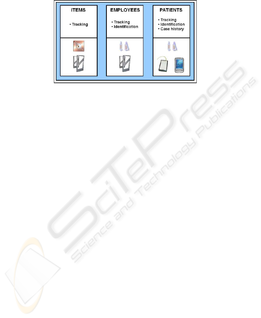
Fig.1. The three scenarios with the corresponding technological solutions.
3 The RFID Technology
Radio-frequency identification (RFID) is an automatic identification method, where the
information is stored on a device called tag or transponder and can be retrieved by
another device called reader using electromagnetic coupling as the way to exchange
data.
3.1 RFID Systems
When we speak about RFID technology we cover a wide range of devices operating
at different frequencies or with different powering methods. According to the different
characteristics of the designed system, the right kind of RFID technology has to be
chosen.
Currently the most used frequencies for RFID devices belong to three different bands:
– Low Frequency (LF) - 125-135kHz: short read range and low data rate. Mainly
used for animal identification or access control.
– High Frequency (HF) - 13.56MHz: medium read range (5-150cm), medium data
rate, more expensive, used in several different fields. Currently the most common
technology.
– Ultra High Frequency (UHF) - 868-930MHz: high read range and data rate, expen-
sive, used in some systems for automatic payment.
This short description gives only the main characteristics of the three technologies, but
it’s important to underline that every kind of RFID system can also be characterized by
the powering method of the transponders.
In this sense we can find passive systems, where the transponder is not equipped with
a battery and the power is taken from the electromagnetic field generated by the reader,
semi-passivesystems, provided with a battery only to monitor environmental conditions
but using RF energy to power the tag response, and active systems, using an internal
power source, such as a battery, within the tag to continuously power the tag and its RF
communication circuitry.
27

3.2 The Adopted Solution
In our case the system chosen is a passive one operating at 13.56MHz. This choice has
been dictated by the following factors:
– Passive tags are less expensive and invasive than active ones. Smart labels have
quite the same dimensions of a sheet of paper and they can be located in delicate
places. The costs are very low, allowing a wide use of tags.
– The HF band is the one which offers the biggest number of devices on the market. In
particular it offers PDA integrable products, allowing the implementation of mobile
devices to be provided to doctors or nurses to retrieve health information stored on
the patient tags.
– The read ranges are a bit small but the positioning of the tags can be made in a way
to optimize the read operations.
– In the HF band the environment has less influence on the system. The tags will be
located on various items realized with different materials. It’s therefore evident that
the quality of the reading has to be guaranteed independently from the material.
In the case of UHF systems the reading can be seriously corrupted in presence of
materials like water or metals.
– The worldwide standardization of these systems allows the creation of fully ex-
portable products, without the limitations due to different frequency ranges like in
the case of UHF technology.
The system has been realized using two different kinds of tag: the identification of the
people has been made using electronic bracelets while in the case of medical equip-
ments we have adopted stiff tags providing better performances of compatibility.
Three different readers have been used:
– The first one was a High Range reader equipped with an embedded Ethernet Con-
nection. This reader was linked to an Access Point to provide wireless connection.
A specific antenna has been designed in order to make the system able to fully
cover the doors of an hospital, which in many cases can be also 2 meters wide.
– The second reader was a small reader, linked via USB connection to a desktop pc.
This workstation was used to read and write the electronic bracelets of the patients.
– The last reader was a PDA integrable one.
4 Technological Means
The most difficult but interesting part of the realization of the hardware infrastructure
concerned the implementation of the RFID gates.
In fact traditional devices didn’t ensure the adequate covering, reaching no more than
1.5 meter of covering, while hospital doors can usually be more than 2 meters wide.
Moreover, due to its application on different moving objects and people, it’s necessary
to ensure that the tag will be read in all its orientations when it moves through the gate.
In fact the tag receives power by magnetic coupling with the reader antenna and it will
receive maximum power in its best orientation, i.e. when the tag is facing the reader
antenna and the magnetic field lines associated with the antenna are orthogonal to the
28

tag.
One method to ensure all orientation detection, is to obtain a rotating magnetic field
projecting an adequate antenna system.
4.1 The Antenna Solution
The final project provides an antenna system covering a passage more than 2 meters
wide using loop antennas, that are recommended as the most suitable for generating the
magnetic field required to transfer energy to batteryless tags.
The realized structure is composed by four loop antennas located on both sides of the
door. In particular on every side there will be two partly overlapped antennas, running
parallel to the transit direction and facing the other pair of antennas.
The overlapped antennas are subject to the phenomenon of mutual coupling: if a current
I flows in a loop, a magnetic field is produced in the surrounding volume; if a second
loop is placed near the first, Faraday’s law asserts that the magnetic field generated by
the first loop flows through the second loop and an induced voltage is generated. This
induced voltage generates along this second antenna a current that generates on its turn
an EM field in the direction opposite to the triggering EM field.
The main factors influencing this phenomenon are the mutual inductance M between
the antennas, which may alter the maximum reading distance, and the antenna factor Q.
In fact, experimental evidences show that raising Q it’s possible to increase the reading
distance, reaching a maximum value influenced by the geometry of the loop.
In order to create the best geometry the system has been studied with the simulation
software FEKO.
Subsequently we studied the matching circuit with the AWR software, in order to have
an adapted system resounding at 13.56MHz frequency.
These circuits have been introduced in the FEKO geometry in order to analyze the
values of the magnetic field, using the following configuration: one antenna has been
powered at 10W and we observed the volume of the generated magnetic field. Sub-
sequently we have been able to obtain the volumes of the other three antennas, to be
powered alternately. Combining the four volumes we reached the full covering of the
door.
5 Software Solutions
5.1 The Databases
Three different databases have been realized (Fig. 2), using MySql as a DBMS:
– The first database manages the localization of items and people. In the final version
of the system there will be a single table with one column for each room of the
structure. The column of the room in which the specified item is located will contain
the number 1 while all the other columns will contain number 0.
– The second database keeps the data of all the patients and is queried when the
electronic case history is read.
29
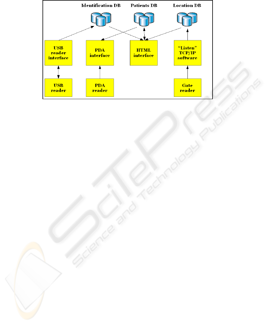
Fig.2. Software solutions.
– The last database keeps trace of all the accesses and modifications made on the
case histories. The function of this database is mainly to help the identification
operations of the patients.
5.2 The Developed Software
The software has been mainly realized using Java as programming language. In par-
ticular we realized four different applications (Fig. 2), the first and the second to be
integrated into a single application:
– The task of the first application is to listen continuously to the RFID gates through
a TCP/IP connection and to update the database keeping the location of the items
and of the employees once a transaction is detected. Every reader has an embedded
Wi-Fi interface in order to reduce the impact of the system on the environment.
It’s also important to know that every tag has a unique UID identification code that
can be used as the identification mean of the tagged item.
The connection with the readers is managed with the APIs provided by the pro-
ducer of the reader. They allow to open a listen channel through which the tags are
detected, the UID code is read and, if needed, the data stored is downloaded.
Once the UID code is read the application searches inside the database the corre-
sponding item and reads the room in which it is located. Every RFID gate is univo-
cally associated with the two adjoining rooms: during the crossing the database is
updated writing a 0 in the field of the room from which the item is going out, and
writing a 1 in the field of the room in which it is entering.
In order to ensure the right identification of the crossing in the final solution every
gate will be provided with two groups of antennas.
The effective crossing from one room to the next one will be noticed only when the
tag will be subsequently read by both the two groups. If the user decides to come
back in the middle of the crossing two different cases occur:
30

• the tag has been read only by the first group. In this case the transition is not
complete and the database is not updated.
• The tag has already been read by the second group. In this case we have a full
transition but when the user moves back the tag is read again from the first
group and the database is updated again.
– The second application is the interface located on the PDA decoding and show-
ing the data kept inside the RFID bracelets regarding the health conditions of the
patient.
– The third application provides an HTML interface to interact directly with the sys-
tem. This application manages the search of the devices and the employees in the
structure and provides a grafic interface to read and write the RFID bracelets, de-
coding also the the electronic case history (Fig. 3).
– The last application interacts with the USB reader allowing the writing and the
reading of the RFID bracelets. This application doesn’t have an interface. It only
uses the APIs provided with the reader to send the data introduced with the HTML
interface to the tags and to download the information stored in the bracelets inside
the database everytime that the reading of a bracelet is performed.
5.3 The Case History
Standard RFID passive tags can usually store data for no more than 256 byte. If opti-
mized, the information kept on a single transponder can be notably extensive.
In our case we divided the information about the patients in two parts. The first part is
formed by the personal data like name, surname, date of birth and address. These data
are not strictly vital and can also be stored on a remote support.
The UID of the RFID bracelet is used to retrieve this information. In the case of the
PDA a Wi-Fi connection to the main server has to be set up in order to download these
data. So, if the PDA is located in a place without Wireless connection this kind of in-
formation will not be provided. In the case of the workstation there will be a direct
Ethernet connection ensuring the chance to get these personal information.
The second part represents vital information, like allergies or blood type. The doctors
or nurses must have the possibility to retrieve these data in every place and in every
situation. The best way to ensure this fact is to keep them directly on the tag.
The information will be organized on the tag creating an array of presence/absence
flags.
Once downloaded, the string retrieved from the tag will be decoded reading the number
1 as Presence of the specific allergy or feature, while the number 0 will mean Absence.
Other specific features like blood type will also be identified by a numeric code.
It’s important to understand that in a passive RFID system the data transfer rate is quite
low. It’s therefore evident that reducing the number of bytes saved on the tag will in-
crease the speed of the reading operations.
In our case we used a 32-byte string. Using the UID of the tag as the mean of identifi-
cation, we were able to use every byte to describe a single feature.
Another way to reduce the number of bytes could have been to use a binary coding of
the information, reducing eight informative flags into one single byte.
31
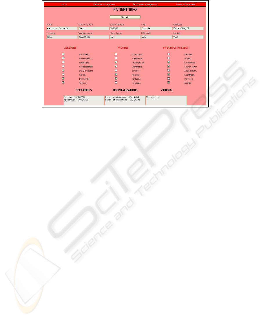
Fig.3. The electronic case history.
6 Testing and Results
6.1 Testing the Antenna
The first part of the testing phase has been centered on the study of the antenna.
First of all we realized a single antenna to test the real performances of the system,
reaching the right matching using a spectrum analyzer.
We tested the performances and we saw that the system reaches the minimum field in-
tensity value required for the activation and the reading of the tag (60mA/m) for every
orientation of the tag, without any presence of magnetic field holes.
Powering a single antenna the system generated a field reaching 1.10m in the direction
of maximum EM coupling and 1m in the other two directions as reading distances.
Subsequently we realized in laboratory a full structure comprising 4 antennas. With the
powering of all the antennas we were able to cover an area 2mx2.15m wide, with a very
good reading rate, over 98%.
Experiments have been subsequently made in order to study the interaction between the
tag and other materials.
No particular interaction has been detected with human body, allowing then the realiza-
tion of the electronic bracelet. Some problems may however occur if the RFID bracelet
remains trapped between two homan bodies, although the extension of the structure no-
tably limits the chances of error.
Metallic objects can modify the EM field and tags cannot be read if the distance from
the object is less than 1cm. In this sense a possible solution may come from the use of
an insulation between the tags and the object.
However the presence of metal can reduce the reading rate down to 80% due to the
possible interaction between different items and to the chance of interposition between
the antennas and metallic structures like stretchers or hand-carts.
32

Some other proofs were made to test the features of the anticollision protocol.
In this case we have seen that no problem occurs because the width of the gate gives to
the system enough time to detect and read up to ten tag simultaneously.
It’s important to underline that in the final system only important items will be tagged.
This implies that the need for a multiple reading of many tags is very low.
Problems also occur in case of overlapping of two tags. If the tags are perfectly over-
lapped they cannot be read. The distance between two tags has to be more than to 2cm
for a good reading. Anyway the case of overlapping is very rare and can be totally
avoided with a good positioning of the tag on the item.
Some improvements can nevertheless be made doing accessory studies on the shape
and the materials of the tags. With high quality tags it’s possible to widen a little bit the
reading ranges and to improve the independence from the environmental conditions.
6.2 Testing the System
Currently the functionality of the system has been tested only inside the laboratory, with
a single gate structure, but the extension towards the creation of a full working system
requires only the realization of other antennas, while no other change has to be made
on the software system.
The final system will be tested inside the Hospital of Borgo San Lorenzo, near Flo-
rence.
In particular the structure will be installed over six doors connecting the Emergency
Room with the other medical wards.
The introduction of the system into a real environmentrequires adequate studies in mat-
ter of electromagnetic compatibility.
The ETSI EN 300 330 standard poses several limitations in this sense: in particular it
sets the limitations of field emission for all RFID systems.
In the specific case of ISO 15693 systems (Identification cards - contactless integrated
circuit(s) cards - Vicinity Cards) the regulation prescribes that the transmitting system
must produce a magnetic field whose intensity at the distance of 10m mustn’t exceed
60dBµA/m.
This value has to be measured in the direction of maximum coupling between the an-
tenna and the receiving probe.
Our system totally satisfies these requirements.
While working inside a delicate structure like an hospital we decided to add another
security feature: every system is connected with an infrared trigger activating the anten-
nas only when the presence of someone crossing the gate is detected, limiting therefore
the emissions due to the magnetic field.
7 Conclusions and Future Work
7.1 Similar Systems
Many other RFID systems have been studied and realized to be used in sanitary en-
vironments. Usually these systems focus only on one single task, without integrating
33

different functionalities onto a single platform.
In particular in Italy RFID has been used in the following situations:
– the management of the blood sacks, providing a safe way to associate the right
blood type to the patients;
– the right associtation between the patients and the medicines;
– the tracking of the patients inside the emrgency rooms.
Some applications covering the tracking of the assets also exist, but in these cases the
UHF active technology is used. With this technology is easier to localize an item, due
to the higher read ranges, but many other inconveniences occur. The features of the
different technologies have already been discussed in the former sections.
Finally the main goal of this system is its modularity: different tasks are integrated
and new ones can be easily introduced, in consideration of the fact that the hardware
infrastructure can be adapted to perform different actions.
7.2 Future Work
Even if this kind of system represents a a global solution interconnecting different ap-
plications into one single structures, some expansions can still be made in order to
integrate other important functionalities.
In fact, once the RFID hardware infrastructure has been realized the integration of new
applications implies only the project of the software solution.
New possible fields of application include:
– The use of RFID tags to identify the correct medications to be given to the patient.
This can help to reduce errors, making safer the procedures of treatment.
– The identification of blood sacks. This is a field in which high security is required
and RFID can eliminate human errors.
– Next to these two examples RFID technology can be used in every situation in
which the tracing and the safe identification of specific gods is required. The chance
to save data on the tags allows to add informative functions to all these scenarios.
Possible expansions of the system can also come from technological improvements. In
this sense one of the most interesting new technologies to be integrated in the system
can be the NFC technology.
Near Field Communication (NFC) is a short-range wireless connectivity technology
(also known as ISO 18092), deriving directly from RFID, that provides intuitive, sim-
ple, and safe communication between electronic devices. Communication occurs when
two NFC-compatible devices are brought within four centimeters of one another.
NFC operates at 13.56MHz and transfers data at up to 424Kb/s. Because the transmis-
sion range is so short, NFC-enabled transactions are inherently secure.
NFC is distinguished by its intuitive interface and its ability to enable largely propri-
etary wireless networking platforms to interoperate in a seamless manner. The primary
uses are to:
– Connect electronic devices, such as wireless components in a home office system
or a headset with a mobile phone.
34

– Access digital content, using a wireless device such as a cell phone to read a ‘smart’
poster embedded with an RF tag.
– Make contactless transactions, including those for payment, access and ticketing.
Using ISO 14443 tags, NFC mobile phones can actually be used instead of PDA’s as
the reading means of the electronic case histories.
Moreover, the interactivity between NFC devices can be used to exchange patient data
between nurses and doctors or between chemistries and hospitals making safer all the
assistance operations and the pharmaceutical prescriptions.
References
1. Bing, B.: Wireless local area networks. Wiley (2002) 415–438
2. Finzkeller, K.: RFID handbook fundamentals and applications in contactless smart card and
identification. Wiley (2003)
3. Jiang, B., Smith, J.R., Philipose, M., Roy, S., Sundara-Rajan, K., Mamishev, A.V.: Energy
scavenging for inductively coupled passive RFID systems. Proceedings of the IEEE Instru-
mentation and Measurements Technology Conference, vol. 2 (2005)
4. Zierhofer, C.M., Hochmair, E.S.: geometric approach for coupling anhancement of magnet-
ically coupled coils. IEEE Transactions on Biomedical Engineering, vol. 43 (1996)
5. Reinhold, C., Scholz, P., John, W., Hilleringmann, U.: Efficient antenna design of inductive
coupled RFID-systems with high power demand. Journal of Communications, vol. 2 (2007)
6. Innovision Research and Technology: Near Field Communication in the real world: turning
the NFC promise into profitable, everyday applications. Innovision Group (2007)
7. Pozar, D.: Microwave engineering. Wiley (2007)
8. Goulbourne, A.: HF antenna design notes, technical application report. Texas Instruments,
Radio Frequency Identification Systems, Tech. Rep. 11-08-26-003 (2002)
9. Compatibility between inductive LF and HF RFID transponder and other radio communica-
tion systems in the frequency ranges 135-148.5KHz, 4.78-8.78MHz and 11.56-15.56MHz.
Electronic Communications Committee (ECC) within the European Conference of Postal
and Telecommunications Admimnistrations (CEPT) (2002)
35
