
AN INCREMENTAL APPROACH TO SOFTWARE
REENGINEERING BASED ON OBJECT-DATA MAPPING
Giacomo Bucci, Valeriano Sandrucci and Enrico Vicario
Dipartimento di Sistemi e Informatica, Universit´a di Firenze, Italy
Keywords:
Evolutionary development,mapping layer, POJO, lightweight ORM.
Abstract:
We address the problem of reengineering legacy systems towards adoption of current predominant technolo-
gies, i.e. object-oriented (OO) programming and relational databases (RDB).
To smooth the reengineering process we follow an evolutionary approach based on the construction of a
mapping layer decoupling application logic from persistent data, so that application reengineering and data
reengineering are made independent and carried out incrementally. The mapping layer does not impose any
particular environment, container or whatsoever. Therefore, program development can be carried out based on
well established OO design principles.
In reimplementing applications, rather than trying to identify applicative classes exclusively from the legacy
code, we follow the guidelines of iterative development processes such as UP, giving the due consideration to
actual user requirements.
1 INTRODUCTION
The term legacy system is used to denote any soft-
ware system written years ago, based on outdated
techniques, but still doing useful work. Improve-
ments to system operation are often required. Cur-
rently, the preferred way for revitalizing such sys-
tems is through Web services and service oriented ar-
chitectures (SOA), wrapping existing data and appli-
cations so as to make them available over the Web
via improved interfaces (Aversano et al., 2001), (Erl,
2005). However, in many situations, reengineering is
unavoidable.
Software reengineering is the examination and al-
teration of a subject system to reconstitute it in a
new form and the subsequent implementation of the
new form (Chikofsky and Cross, 1990). Software
reengineering is considered to be made of three ma-
jor phases: reverse engineering in which the legacy
code is reversed into a more abstract, and easier to un-
derstand, representation of the system; modification
in which the abstract representation (i.e. the model)
is analyzed for possible changes of functionality and
implementation technique; and forward engineering
in which the system is reimplemented from the re-
constructed model on a possibly different platform
and on the basis of new development and program-
ming paradigms (Jacobson and Lindstrom, 1991),
(Periyasamy and Mathew, 1996).
Reverse engineering is is the process of analyzing
a subject system to identify the system’s components
and their interrelationships and create representations
of the system on another form ar at higher level of
abstraction (Chikofsky and Cross, 1990)
Understanding structural aspects is more impor-
tant that understanding any single algorithmic com-
ponent (Tilley and Smith, 1996), (Biggerstaff et al.,
1994). Failure to evaluate the existing architecture
will lead to gratuitous inconsistencies between the
legacy and target systems (Bergey et al., 1999). It
is no surprise that the largest share of the literature on
reengineering is actually on reverse engineering and
program comprehension (Canfora et al., 1993), (Ab-
battista et al., 1993), (Periyasamy and Mathew, 1996),
(Sneed, 1996), (Penteado et al., 1998), (Cimitile et al.,
1999), (DiLucca et al., 2000), (Guo, 2002), (Eisen-
barth et al., 2003), (Wu et al., 2005).
However, a weakness of most of the methods pro-
posed in the above-mentioned papers is that they de-
rive the architecture of the target system almost ex-
clusively from the analysis of legacy code. In partic-
ular, target classes are directly derived from the data
units and the program units of the legacy system. This
may lead to reimplementation of obsolete program
165
Bucci G., Sandrucci V. and Vicario E. (2008).
AN INCREMENTAL APPROACH TO SOFTWARE REENGINEERING BASED ON OBJECT-DATA MAPPING.
In Proceedings of the Third International Conference on Software and Data Technologies - SE/GSDCA/MUSE, pages 165-173
DOI: 10.5220/0001883601650173
Copyright
c
SciTePress

features, no longer valuable for the users.
It has been observed that to tackle the essence
of the problem of recovering data at the conceptual
level, it is necessary to integrate the bottom-up ap-
proach with a top-down approach, taking into account
information obtained from end users, programmers,
designers, etc. (Abbattista et al., 1993).
More recent approaches put a greater emphasis on
actual user requirements. In (Dugerdil, 2006) and
(Dugerdil and Jossi, 2007) a process similar to UP
(Unified Process) is proposed. In (Stevenson and
Pols, 2004) an agile reengineering process is sug-
gested, which skips altogether the analysis of source
code.
An incremental approach for migrating legacy in-
formation system has been proposed in (Brodie and
Stonebraker, 1995). In this approach, the legacy and
the target system operate in parallel throughout mi-
gration. The target system is built incrementally, start-
ing from some initial application accessing only a
small portion of the target database. As the migra-
tion progresses, the target system grows. Eventually,
it will perform all the functionalitiesof the legacy sys-
tem. At that point the latter can be retired. During
migration, the legacy and the target systems are sup-
posed to interoperate through gateways.
This paper proposes an incremental method for
reengineering, which, in a general sense, is similar
to that of (Brodie and Stonebraker, 1995). However,
rather than employing gateways to interoperate the
old and the new (parts of the) system, it uses a map-
ping layer to obtain a complete decoupling of persis-
tent data from application logic. As a result, applica-
tions are converted selectively on top of the mapper;
the mapper itself grows incrementally so as to accom-
plish subsequent conversionscycles. Convertedappli-
cations are made operational before acting any change
to the legacy database. When the application layer
is completely reengineered, also the legacy database
can be changed/upgraded, This will usually lead to
the conversion of legacy data to the relational model
or to the improvement of the existing relational DB.
Eventually, the mapper can be replaced by a light off-
the-shelf object-relational mapper (ORM).
The proposed method has been applied in reengi-
neering a small-medium sized system for meteorolog-
ical applications. This system was grown from an ini-
tial version in which a few applications managed a
set of binary files to a version which comprised many
more applicative programs and a relational database
(Microsoft Access), as well as the original data struc-
tures. Though the size of the system was moderate
(about 40 Data Base tables, 60 applicative programs
– three of which did 70% of the work), there was a
variety of problems, including duplicated data, com-
posite access key, blob field containing information to
be parsed, and more. In addition almost no documen-
tation was available.
Reengineering resulted in a system with a new re-
lational data base and a set of OO applications written
in Java.
The rest of the paper is organized as follows. Sec-
tion 2 discusses related work. Section 3 gives an out-
line of the method, while section 4 presents some
some relevant implementation issues. Conclusions
are drawn in section 5.
2 RELATED WORK
In (Brodie and Stonebraker, 1995) a migration
methodology, called Chicken Little, is proposed. The
methodology consists in 11 steps, performed incre-
mentally and repeatedly. The first step is the anal-
ysis of the legacy information system. Other steps
follow, including the design of both target applica-
tions and target data base, their incremental instal-
lation together with the installation of the necessary
gateways. With this methodology, applications and
persistent data are reengineered in parallel; data is
stored in both the migrating legacy and the growing
target system. This poses a relevant problem, i.e. co-
existence within the same software systems of parts
which exploit different technological solutions (Can-
fora et al., 1998). In (Brodie and Stonebraker, 1995)
this problem is addressed through gateways and gate-
ways coordinators. A gateway-free approach is pro-
posed in (Wu et al., 1997). To avoid gateways, the
target system is not put in production while the legacy
system is being migrated, so that the legacy system
remains fully productive during the whole migration
process.
As far as reverse engineering is concerned, several
method have been proposed in the course of the last
decade. One of the earliest regards object-oriented
reverse engineering of programs written in COBOL
(Sneed, 1996). The issue was how to restructure ex-
isting programs so that certain data structures could
be converted to abstract data types, assigning to them
elementary program operations. The author says that
there is no automatic way to identify the data objects,
proposinga method which is essentially based on sub-
jective judgement, with the chance that unused or ir-
relevant code is chosen. The method enforces reengi-
neering of programs and data at the same time.
A similar approach has been taken in (Cimitile
et al., 1999) and (DiLucca et al., 2000). In (Cimitile
et al., 1999) objects are identified from persistent data
ICSOFT 2008 - International Conference on Software and Data Technologies
166

stores, i.e. files or tables in the database, while pro-
gram units, i.e. programs and subroutines, are used
to derive object methods. Metrics for object-oriented
design (Chidamber and Kemerer, 1994) are used in
assigning program units as object methods, trying to
minimize the coupling among the discovered objects.
However, the problem of reengineering is left open,
as the authors conclude that further work is needed
to understand how the proposed decomposition can
be actually used in reengineering. In (DiLucca et al.,
2000) the method of (Cimitile et al., 1999) is extended
so as to recover also relationships among objects and
produce the system class diagram. The construc-
tion of the class diagram proceeds through a number
of steps, including the identification of relationships
among candidate classes, as well as the validation of
the model. A classification of different cases in map-
ping relational tables onto objects is in (Canfora et al.,
1998).
In (de Guzman et al., 2005) a tool is pre-
sented which, starting from the physical schema of
a (relational) database, translates it into a vendor-
independent metamodel which, in turn, is translated
into a class diagram representing the possible con-
ceptual schema used during the development of the
database. The criterion enforced by the tool is to de-
vise one class for each table of the data database. The
class diagram, i.e. the OO model of the systems, is
then used as the basis of a forward engineering stage,
which is carried out automatically by the tool, pro-
ducing a reengineered version of the systems.
In (Dugerdil, 2006) and (Dugerdil and Jossi,
2007) a method is proposed for reconstructing an ar-
chitecture whose elements are mapped to concepts of
the business domain. The method is strongly influ-
enced by the Unified Process (UP). It begins building
a representation of the business process in terms of
use-cases. These are reconstructed by gathering in-
formation of the system usage from all the involved
people. The recovered use-cases are then analyzed to
produce the analysis model of the system in standard
UP analysis class stereotypes (Boundary, Control and
Entity classes). The resulting analysis model repre-
sents the hypothetical architecture of the software. El-
ements of this architecture are related to visible par-
titions of the existing system (files, tables, etc.). The
next step is a dynamic analysis of the source code; this
is performed by executing the recovered use-cases on
the existing system. Recorded execution traces are
then examined to identify the classes involved in the
execution of each use-case. Finally, identified classes
are mapped to the analysis model, leading to what
could be called the model for forward engineering.
A relevant result of (Dugerdil and Jossi, 2007) is that
it confirms that the pure bottom-up approach, based
on the static analysis of source code, may be waste-
ful of time and effort. In fact, the experimental data
of (Dugerdil and Jossi, 2007) reveal that only a small
fraction of the overall program modules are involved
in the processing of the use-cases. Being driven by
user requirements, the method of (Dugerdil, 2006)
produces an analysis model that represents what the
users want from the system. As such, the model
includes only those parts of the legacy system that
call for reengineering, excluding unused or irrelevant
code. In addition, the recovered model captures the
new user requirements, thus leading to improvements
over the old system.
The agile reengineering process described in
(Stevenson and Pols, 2004) was motivated by fail-
ure of an initial attempt to rewrite existing code (in
Java). The authors maintain that the reengineering
process should be driven by the actual user require-
ments and carried out incrementally, by reimplement-
ing selected functionalities separately, skipping alto-
gether the analysis of legacy code.
3 OUTLINE OF THE METHOD
The objective of reverse engineering and modification
stages (section 1) is the definition of an architecture
of the target system, so as to incorporate actual user
requirements and to take into account actual system
operations. Rather than relying on tools that automat-
ically generate model classes from the existing code,
we follow the guidelines of iterativedevelopment pro-
cesses such as UP, starting from current user require-
ments.
As a result, the first step of the method is to re-
coverall possible use-cases. This is done by gathering
information from the users, so as to identify the key
problems and to incorporate in the analysis what the
users want, avoiding those aspects that have no value
for them.
Once the use-cases are recovered, they can be exe-
cuted on the existing system in order to identify which
are the persistent legacy data involved in their exe-
cution – this corresponds to the dynamic analysis of
(Dugerdil and Jossi, 2007). To better understand sys-
tem behavior, this activity can be supplemented with
inspection of source code.
The data structures identified in the legacy data
base is the starting point for deriving the classes to
be implemented in the target system and for build-
ing the OO model of the business domain. To derive
the OO model of the business domain, we follow the
meet in the middle approach of (Fowler, 2003), mov-
AN INCREMENTAL APPROACH TO SOFTWARE REENGINEERING BASED ON OBJECT-DATA MAPPING
167
ing bottom-up (from legacy data) and top-down (from
recovered use-cases).
Starting from the OO model of the business do-
main, we procede as follows.
1. Select one application to be converted on the ba-
sis of recovered use-cases; identify the part of the
legacy data that are related to it.
2. Design the (part of the) mapping layer that maps
the model objects involved in the selected appli-
cation to the part of the legacy data identified at
point 1. The mapper must take care of: (i) assign-
ing values contained in the legacy database to ob-
jects’ attributes; and (ii) making persistent (in the
legacy database) the values of object attributes.
3. Implement and test both the application and the
mapper of the previous points. For testing pur-
poses, the selected legacy data should be dupli-
cated so that testing does not impact or impair the
legacy database.
4. When the selected application and the related
mapper have been completely tested, deploy them
in parallel with the remaining part of the legacy
system, removing the old version of the applica-
tion. The deployed application operates on actual
legacy data.
5. Iterate steps from 1 to 4 until all applications have
been reimplemented.
Note that the process is similar to that of (Brodie
and Stonebraker, 1995), in the sense that reengineer-
ing is made incrementally. However, there is a great
difference, since we leave the legacy database un-
changed while applications are reengineered. As a re-
sult the problem of coexistence is mitigated. At least
it is encapsulated in a single component: the mapping
layer which grows in parallel throughout the migra-
tion process.
There is quite a difference between gateways and
mappers: while gateways essentially mediate between
different technologies, mappers mediate between dif-
ferent conceptual models. In our case, the mapper
is used to adapt persistent data to a general OO do-
main layer. Relying on the mapper, applications are
converted selectively on top of it. The mapper it-
self grows incrementally so as to accomplish subse-
quent conversions cycles. Converted applications can
be made operational before acting any change to the
legacy database.
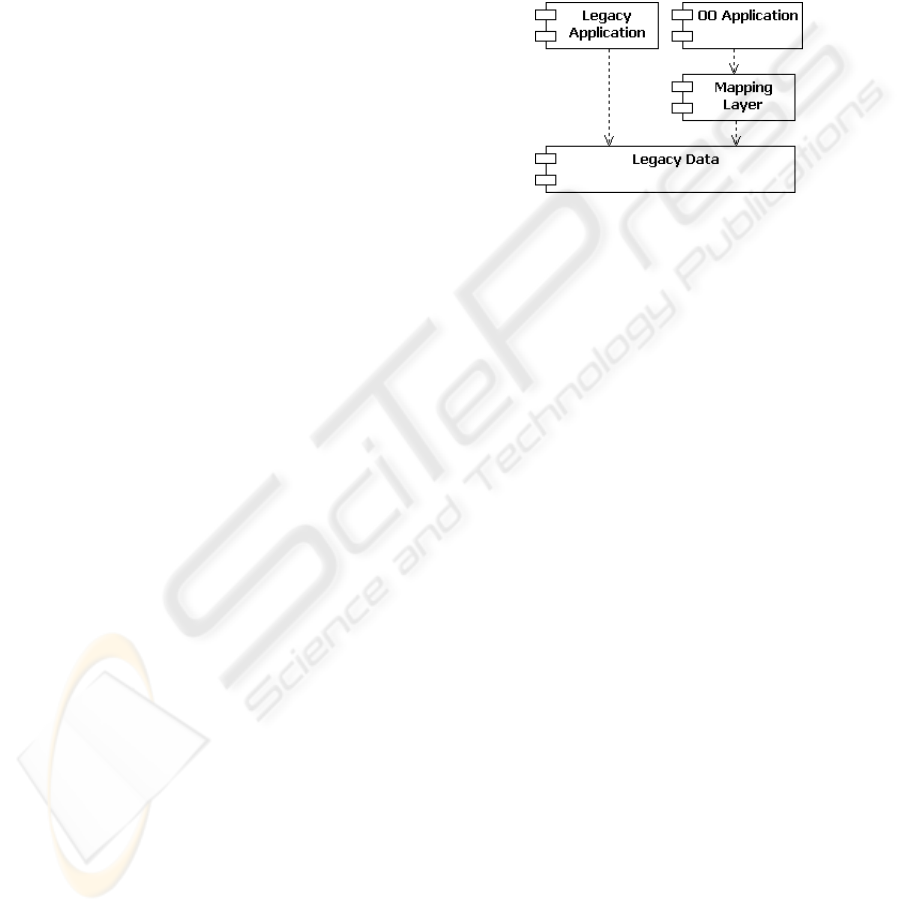
Figure 1 shows the structure of the system in the
middle of migrating applications, under the assump-
tion that reengineered applications can cohabit with
those not yet converted. Referring to Figure 1, legacy
applications directly use the legacy data, while com-
ponentsof reengineeredapplication (OO Application)
use the mapping layer to access the same legacy data.
The new components obsolete legacy applications in-
crementally, while delivering regular new features to
users. As soon as a given OO component is deployed,
the legacy code implementing the same functionali-
ties is removed. Application reengineering terminates
when no useful legacy program is left. At this point
the new domain layer is totally object-oriented while
legacy data are untouched.
Figure 1: System structure during migration.
The mapper is essential to allow independent ap-
plication reengineering. Furthermore, the develop-
ment of a mapper for the legacy database is unavoid-
able, since it is the only means to deal with odd data
structures (for instance, information spread in a non-
ordered manner within blob fields) that are usually
found in such databases.
6. When all applications are converted, the legacy
data can also be reengineered to a more effective
relational model. In this case the process will be
top-down, from the OO model to the relational
schema. The new database can be implemented
in the form of a prototype under the RDBMS of
choice. The prototype can be thoroughly tested
using reengineered applications.
7. Since the new database will require its own map-
per, there are two possible choices:
a) implementthe new mapper. This may appear as
an unwitting effort, though many components
of the legacy data mapper so far developed can
be reused and/or readapted (see section 4.3);
b) resort to a light, off-the-shelf ORM such as
(Bauer and King, 2004). This is the preferred
solution since it entails usage of standard com-
ponents.
8. When the prototype database is fully tested,
legacy data can be transposed in one-shot to the
new relational form. At this point the old legacy
system is completely replaced.
ICSOFT 2008 - International Conference on Software and Data Technologies
168
4 IMPLEMENTATION ISSUES
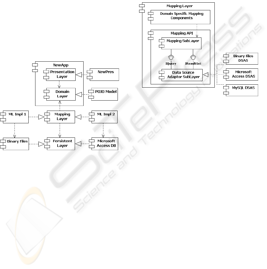
Figure 2 develops on the right side of Figure 1, show-
ing how architectural components are implemented.
NewApp stems for any reengineered application. In
accordance with the concept of layering, a reengi-
neered application is divided into Presentation and
Domain layers. This separation permits confinement
of the aspects related to application functionalities in
the Domain layer. The Domain layer contains both
the classes representing entities of the business do-
main, and the classes acting as controllers or imple-
menting (part of) the application logic. The Domain
layer is implemented in terms of plain old java objects
(POJO) (Richardson, 2006). (We named NewPres
the component implementing the presentation layer to
point out that also this layer is affected by reengineer-
ing.)
Figure 2: Dividing the overall architecture into layers.
Figure 2 has been drawn so as to make evident
that the mapping layer may have more than a single
implementation. The schematization reflects our case
study, with a mapping for binary files (ML Impl 1)
and a mapping for a relational database (ML Impl 2).
However, this is not to be interpreted as if they were
two distinct packages. In fact there are functional-
ities, that every concrete mapper must provide, that
can be factored out and used by any specific mapper
implementation; on the other hand, any specific data
organization requires its own adapter. In other words,
the two mappers reported in Figure 2 are to be consid-
ered as the two parts of a mapper that deals with two
different data organizations.
The structure of the Mapping layer is depicted in
Figure 3. The stratus named Domain Specific Map-
ping Components has the role of adapting Mapping
API to the specific applicative domain and will be dis-
cussed in section 4.2. The Mapping API is the basic
component of the Mapping layer. As discussed here-
after, it implements all mapping functionalities in a
general manner, so as to be reusable across different
application domains.
The Mapping API is itself divided into two sub-
layers: the upper sublayer provides the interface to-
wards the Domain layer, while the lower sublayer en-
capsulates the differences among data organizations
(in Figure 3, three different implementations for lower
sublayer are depicted).
Figure 3: Decomposition of the Mapping Layer.
The Data Source Adaptor Sublayer (DSAS) of
Figure 3 solves the technological adaption problem
and provides uniform representation of underlying
data in the form of a result-set (which is independent
of the technology used to store persistent data). DSAS
does not depend on the particular application domain;
it only depends on the specific database (i.e. Oracle,
Access, MySQL, hand-made DB).
Domain-specific mapping components are used to
implement the mapping between model objects and
(standardized) results-sets. As a result, the Mapping
sublayer is unaware of both the actual organization of
persistent data and the OO domain model.
4.1 The Data Source Adaptor
The connection between the Mapping sublayer and
the Data Source Adaptor is actually supported by the
two interfaces
IQuery
and
IResultSet
, which are
provided by the latter (Fig. 3). Through
IQuery
the
Data Source Adaptor accepts queries from the above;
through
IResultSet
the results of those queries are
presented in the form of a result-set. Query formats
can also be standardized; therefore, if persistent data
are in the form of a relational DB, the role of the
Data Source Adaptor is to translate a standardized
query into the SQL dialect of the given RDBMS.
AN INCREMENTAL APPROACH TO SOFTWARE REENGINEERING BASED ON OBJECT-DATA MAPPING
169
This means that a given DSAS can be ported, with-
out any modification, to other systems with the same
RDBMS. On the other hand, the migration to a differ-
ent RDBMS requires only the implementation of the
related DSAS, with no impact on the above levels.
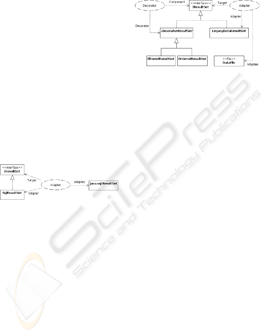
In the following we discuss the implementation of
interface IResultSet. Due to space limitations we re-
tain from discussing interface
IQuery
. We shall refer
to both the case of an underlying RDB and the case of
a generic legacy storage.
Figure 4 shows how interface
IResultSet
is pro-
vided when the data are in relational form. The design
pattern Adapter (Gamma et al., 1995) is used to adapt
java.sql.ResultSet
(the object returned from calls
to JDBC library) to the target interface
IResultSet.
Class
SQLResultSet
is the actual adapter.
Referring to Figure 3 a query to the persistence
layer is made by the Mapping sublayer via interface
IQuery.
The query is translated into the vendor-
specific SQL query, which is actually executed by
calling the JDBC library. This returns an object
of class
java.sql.ResultSet,
which is adapted to
IResultSet
by
SQLResultSet
.
Figure 4: Implementing interface IResultSet for a relational
data base.
When legacy data are not in the relational
form, they are adapted to
IResultSet
by class
LegacyDataResultSet
(see Figure 5). More pre-
cisely, there is a specific adapter (i.e., an object deriv-
ing from class
LegacyDataResultSet
) for any spe-
cific data format. To avoid overloading the adapters
with to many functionalities, they only perform the
bare adaption of legacy data to
IResultSet
(see Fig.
5). At the occurrence, we use appropriate Decorators
(Gamma et al., 1995) to add properties to the adapted
data.
For instance, consider the file
sensor.dat
which
collects the data relative to all the sensors in our sys-
tem, and assume that an application only needs the
data relative to the sensors located in a specific ge-
ographic area; then: (i)
sensor.dat
is adapted to
IResultSet
by an object of class
SensorResultSet
(a subclass of
LegacyDataResultSet
); and (ii) the
decorator
FilteredSensorResultSet
(a subclass of
FilteredResultSet
) is applied to produce a desired
result set.
Figure 5: Implementing interface IResultSet for a legacy
data base.
4.2 The Mapping sublayer
In order to make possible the replacement of the
legacy data mapper with a mapper for the new
database, without impacting the Domain layer, the
Mapping sublayer must be independent of the Do-
main layer. As mentioned at the end of section 4,
this is done through domain-specific mapping com-
ponents. More precisely, we resort to the concept
of DAO (Data Access Object) as suggested in (Bauer
and King, 2004) and (Sun-Microsystems, 2008).
In Figure 6, the Domain layer has been divided
into two sublayers: Model and Service. The former
contains the objects that correspond to business do-
main entities (e.g., sensors), while the latter contains
objects that are largely responsible for implementing
the logic of application (e.g., computation of the av-
erage temperature of the day). Correspondingly, we
talk of model objects and service objects.
The Presentation layer (not shown in Figure 6)
routes user requests to the service objects that are in-
volved in executing any given transaction. In turn,
service objects interact with model objects to per-
form the transaction. This may entail loading model
objects from persistent storage and/or storing them
back. Load and store operations are performed by
DAOs. Figure 6 shows that the interface of DAOs
is implemented by the Mapping layer, as part of the
Domain Specific Mapping Components. DAOs en-
capsulate any embedded code, making it invisible at
level of Domain layer.
The Mapping sublayer implements the interface
Session
used by the Domain layer, via DAOs, to es-
tablish a session for accessing the database. It also
implements all the functionalities that are needed for
managing access to the database, including caching,
record locking, transaction commit and roll-back. In
our implementation, the mapping API takes the form
of a reusable library, that can be ported across differ-
ent application domains.
ICSOFT 2008 - International Conference on Software and Data Technologies
170
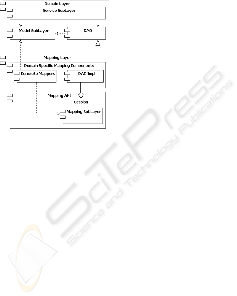
Figure 6: Making the Domain layer independent of the
Mapping sublayer.
DAOs and Concrete Mappers are Domain-
Specific Mapping Components. DAOs provide the
interface for accessing the persistent data, while Con-
crete Mappers relate (the attribute fields) of model ob-
jects to the corresponding fields in the database.
A Concrete Mapper is an extension of class
AbstractMapper
(defined within the Mapping Sub-
layer), overriding methods
Load
and
Save
. Both
methods have two parameters: a result set and an
object to be mapped. Method
Load
fills object’s at-
tributes from the result set, while method
Save
fills
the result set from objects’ attributes. In short, Con-
crete Mappers take the duty of translating database
tables into objects’ attributes and vice versa. In so do-
ing, a concrete mapper can perform any specific op-
eration such as parsing blob fields in order to identify
embedded information.
A request from the Service layer goes through
DAOs and interface
Session
to the Mapping API,
which uses concrete mappers to relate objects and
persistent data. Concrete mappers can either be im-
plemented as standard Java classes (as we did in our
implementation) or described through an XML file.
In the second case, known as the Metadata Mapping
Pattern, it is the Mapping API that builds the appro-
priate mappers on the basis of XML metadata.
Let us make an example to show how the architecture
of Figure 6 works. To this end, consider a transaction
in which the Service sublayer needs to interact with
the object of class
Sensor
whose ID is 5. Schemati-
cally, this is done in the following manner:
DaoFactory f = new DaoFactory();
dAO = f.getDao(’’Sensor’’);
Sensor s = dAO.getByID(5);
s.set(..);
The first statement instantiates a factory of DAOs;
the second obtains the specific DAO for the class
Sensor;
the third obtains the sensor object that in the
database is identified for having the field ID equal to
5; the last statement modifies some attribute of the in-
stantiated object
s
. Note that the method
getByID()
hides all the details associated with use of the Map-
ping API.
Assume that the system follows the policy called
“one transaction per session”, so that the two terms
correspond each other. The code implementing a
transaction is encapsulated within a class which is re-
sponsible of opening a session, performing the trans-
action and committing it. When the transaction is
committed, the Mapping API automatically recog-
nizes the objects whose attributes have been modified,
so as to update the related data in the persistent store.
Actually, when an object is brought into memory, its
version (a hash function of the values of its attributes)
is saved by the API, so that, when the transaction is
committed (i.e., when the session is closed), the API
writes back the object only if it has been changed.
4.3 Converting the Legacy Data
In section 3 we stated that data reengineering should
start only when application reengineering is termi-
nated. The reason is that we want to make sure that
the new applications correctly replace the old ones.
However, this does not impede construction and ex-
perimentation of a prototype new database, in paral-
lel with application reengineering. The mapper pro-
vides guidance in understanding how the target RDB
should be structured with respect to the OO applica-
tions. This may provide insights into OO applica-
tions, imposing refactoring of both the OO applica-
tions and the prototype RDB to keep them well-tuned.
In other words, the process of constructing target ap-
plication and data structure becomes iterative in a nat-
ural manner.
As stated at point 7 of section 3, the new database
will require its own mapper. With the architecture of
Figure 6 we have two choices:
a) reimplement the mapper by reusing and/or
readapting the components of the already devel-
oped mapper. Referring to Figure 6 the Mapping
AN INCREMENTAL APPROACH TO SOFTWARE REENGINEERING BASED ON OBJECT-DATA MAPPING
171

API of can be completely saved, while Concrete
Mappers and DAOs need reworking;
b) use an off-the-shelf ORM at the marginal cost
of reimplementing Concrete Mappers and DAOs.
Use of an off-the-shelf ORM is now possible since
the new database has a well defined structure.
A light-weigh ORM like Hibernate (Bauer and
King, 2004) does not impose constraint to the ap-
plication programmer, giving him the freedom to
implement applications in form of POJOs.
The conversion of legacydata to the new relational
DB requires a specific program, which can be built us-
ing the functionalities of the already developed map-
pers. Differently from applicative programs, legacy
data can be converted (translated) overnight and de-
ployed in a single step. The new database is to be
deployed only after all applications have been reengi-
neered.
A final consideration is in order. The mapper is the
key component for revitalizing an old system. It gives
a view of the legacy data as if they were objects, al-
lowing the use of standard, consolidated OO tech-
niques. The mapper itself is developed incrementally,
starting from the subset of legacy data that are in-
volved in the selected application to be reengineered,
and growing to cover all legacy data of interest. The
mapper is the key element to perform independent
reengineering of application. It also provides guid-
ance in structuring the target RDB with respect to
reengineered applications.
5 CONCLUSIONS
We presented an evolutionary method for reengineer-
ing legacy systems in terms of Java programs and re-
lational DB, which is strongly based on the concept of
mapping layer, a component which adapts persistent
data to a general OO domain layer.
The proposed method solves the problem of con-
verting applications and legacy data, through a pro-
cess which confine all idiosyncrasies in the mapping
layer. This is first used to provide access to the legacy
database on behalf of reengineered applications. As
a result, the applications layer is reimplemented and
deployed before the legacy database is updated to the
relational form.
Application reengineering can be carried out in a
gradual, incremental manner, by replacing a single
application at time. The mapper itself is built incre-
mentally as required by reengineered applications.
The mapper has a well defined interface, so that,
once the database has been converted to an improved
relational form, it can be replaced by an off-the-shelf
ORM. As a result, when applications have been reim-
plemented and the structuring of the new relational
DB is completed, legacy data can be loaded in the
database and the ORM put in place of the mapping
layer, making the system fully operational.
The proposed method has been successfully ap-
plied in reengineering a system used for processing
meteorological data.
ACKNOWLEDGEMENTS
We are grateful to Jacopo Torrini for his cooperation
during all the stages of reengineering the system at
hand.
REFERENCES
Abbattista, F., Lanubile, F., and Visaggio, G. (1993). Re-
covering conceptual data models is human-intensive.
In Proc. of SEKE’93, pages 534–543.
Aversano, L., Canfora, G., Cimmitile, A., and DeLucia, A.
(2001). Migrating legacy systems to the web: an ex-
perience report. In Proc. CSMR 2001, pages 148–157.
Bauer, C. and King, G. (2004). Hibernate in Action. Man-
ning Publication Co.
Bergey, J., Smith, D., Tilley, S., Weiderman, N., and Woods,
S. (1999). Why reengineering projects fail. Technical
Report TR - 010, CMU/SEI.
Biggerstaff, T. J., Mitbander, B. G., and Webster, D. E.
(1994). Program understanding and concept as-
signment problem. Communications of the ACM,
37(5):72–83.
Brodie, M. L. and Stonebraker, M. (1995). Migrating
Legacy Systems - Gateways Interfaces and the Incre-
mental Approach. Morgan Kaufmann, San Francisco,
California.
Canfora, G., Cimitile, A., Lucia, A. D., and Lucca, G.
A. D. (1998). Devising coexistence sta’rategies for
objects with legacy systems. In Proceedings of the
1st Colloquium on Object Technology and System-
Reenineering, Oxford, UK.
Canfora, G., Cimitile, A., and Munro, M. (1993). A reverse
engineering method for identifying reusable abstract
data types. In Proc. of WCRE’93, pages 73–82.
Chidamber, S. R. and Kemerer, C. F. (1994). A metrics suite
for object oriented design. IEEE Trans. Soft. Eng.,
20(6):476–493.
Chikofsky, E. J. and Cross, J. H. (1990). Reverse engineer-
ing and designn recovery: a taxonomy. Computer,
7(1):13–17.
Cimitile, A., DeLucia, A., DiLucca, G. A., and Fasolino,
A. R. (1999). Identifying objects in legacy systems
ICSOFT 2008 - International Conference on Software and Data Technologies
172

using design metrics. The Journal ofSystems and Soft-
ware, 44(3):199–211.
de Guzman, I. G.-R., Polo, M., and Piatini, M. (2005). An
integrated environment for reengineering. In Proc. of
ICSM’05, pages 165–174.
DiLucca, G. A., Fasolino, A. R., and DeCarlini, U. (2000).
Recovering class diagrams from data-intensive legacy
systems. In ICSM 2000, pages 52–63.
Dugerdil, P. (2006). A reengineering process based on the
unified process. In Proc. of ICSM’06, pages 330–333.
Dugerdil, P. and Jossi, S. (2007). Role-based clustering of
software modules. In Proc. of ICSOFT 2007, pages
5–12.
Eisenbarth, T., Koschke, R., and Simon, D. (2003). Locat-
ing features in source code. IEEE Trans. Softw. Eng.,
29(3):210–224.
Erl, T. (2005). Service-Oriented Architecture (SOA): Con-
cepts, Technology, and Design. Prentice Hall.
Fowler, M. (2003). Patterns of Enterprise Application Ar-
chitecture. Addison Wensley.
Gamma, E., Helm, R., Johnson, R., and Vlissides, J. (1995).
Design Patterns. Addison-Wesley.
Guo, J. (2002). A systematic method of reusing objects
extracted from legacy systems. In Proc. of ECBS ’02,
pages 177–184.
Jacobson, I. and Lindstrom, F. (1991). Re-enginnering
of old systems to an object-oriented architecture. In
OOPSLA ’91, pages 340–350.
Penteado, R., do Prado, A. F., Masiero, P. C., and Braga, R.
T. V. (1998). Reengineering of legacy systems based
on transformation using the object-oriented paradigm.
In Proc. of WCRE’98, page 144.
Periyasamy, K. and Mathew, C. (1996). Mapping a func-
tional specification to an object-oriented specification
in software re-engineering. In Proc. of CSC ’96, pages
24–33.
Richardson, C. (2006). POJOs in Action. Manning Publi-
cation Co.
Sneed, H. M. (1996). Object-oriented cobol recycling. In
Proc. of WCRE 1996, pages 169–178.
Stevenson, C. and Pols, A. (2004). An agile approach to a
legacy system. In Proc. of XP 2004, volume 3092 of
Lecture Notes in Computer Science, pages 123–129.
Sun-Microsystems (2008). Core j2ee patterns - data
access object. http://java.sun.com/blueprints/
corej2eepatterns/Patterns/.
Tilley, S. R. and Smith, D. B. (1996). Towards a framework
for program understanding. In Proc. WPC ’96, pages
19–28.
Wu, B., Lawless, D., Bisbal, J., Grimson, J., Wade, V.,
OSullivan, D., and Richardson, R. (1997). Legacy
system migration: A legacy data migration engine. In
Proceedings of the 17th International Database Con-
ference (DATASEM ’97), pages 129–138, Brno, Czech
Republic.
Wu, L., Sahraoui, H. A., and Valtchev, P. (2005). Coping
with legacy system migration complexity. In Proc. of
ICECCS ’05, pages 600–609.
AN INCREMENTAL APPROACH TO SOFTWARE REENGINEERING BASED ON OBJECT-DATA MAPPING
173
