
TOWARDS A METHODOLOGY FOR MODELLING
INTEROPERABILITY BETWEEN COLLABORATING
ENTERPRISES
Anders Carstensen, Kurt Sandkuhl
CenIT, Jönköping University, PO Box 1026, SE-551 11, Jönköping, Sweden
Lennart Holmberg
Kongsberg Automotive, PO Box 504, SE-565 28 Mullsjö, Sweden
Keywords: Enterprise Modelling, Open Distributed Processing, Connector View, Viewpoint.
Abstract: In this paper we have described a collaboration study between two companies in a networked organisation.
The main contribution is the connector view by which it is possible to model the collaboration without
major changes in existing enterprise models, although the collaboration actually may effect several elements
in the original model. Supporting objects are used to connect elements in the connector view to the original
model, thereby establishing correspondences between the connector view and the enterprise view.
1 INTRODUCTION
Enterprises need to develop products faster than ever
before, to stay competitive on the market. In this
scenario it is of vital interest to study extended or
virtual enterprises. Collaboration between
enterprises is a fast way of incorporating knowledge
and capabilities. Collaborating enterprises need to
exchange information managed by their IT-systems,
which is regarded as the interoperability problem.
This is only one facet of the problem. Others are
how the collaborating enterprises shall: organise
their business activities; optimise their internal
organisations and ICT-systems. In this view the
main contribution with this paper is an elaborated
draft of a methodology for how to facilitate
interoperability. The methodology draft is based on
a use case developed within the MAPPER project in
the EU 6
th
frame work program.
2 BACKGROUND
In this particular application case we have studied
the collaboration between two companies (Partner A
and Partner B) in a networked organisation and the
need of information exchange generated by their
various IT-systems.
In the extended enterprise several companies
builds a partnership in a networked organisation.
The collaboration between the enterprises is based
on the specific competences that the enterprises can
provide. The extended enterprise is a more stable
configuration compared to the virtual enterprise,
where the collaboration is maintained only as long
as a specific project lasts (Szegheo 2000). In
addition to the enterprise integration aspects the
networked organisations have to also manage the
interoperability problems.
Interoperability, defined as “the ability of two or
more systems or components to exchange
information and to use the information that has been
exchanged” (IEEE 1990), is not only a matter of
transferring data. It has to be managed on the three
different layers of an enterprise: Business,
Knowledge and ICT-systems (Chen and Doumeingts
2003). Meaning: how the collaborating enterprises
try to adapt their business activities in order to
optimise the collaboration (business layer); how
roles, skills and competencies are managed
(knowledge layer); how the ICT systems of the
enterprises are able to communicate the information
they generate (ICT layer). The semantic dimension
333
Carstensen A., Sandkuhl K. and Holmberg L. (2008).
TOWARDS A METHODOLOGY FOR MODELLING INTEROPERABILITY BETWEEN COLLABORATING ENTERPRISES.
In Proceedings of the Tenth International Conference on Enterprise Information Systems - DISI, pages 333-338
DOI: 10.5220/0001714903330338
Copyright
c
SciTePress

moves through the layers in order to capture the
different concepts and their mutual meaning, and are
believed to best be represented and operationalised
using ontologies (Chen and Doumeingts 2003).
Databases, considered solving interoperability
and data integration problems, failed mainly due to
the rigidity of the database schema, which disallow
semantic data integration. “Semantic integration is
the task of grouping, combining or completing data
from different data sources by taking into account
explicit and precise data semantics in order to avoid
that semantically incompatible data are structurally
merged”(Ziegler and Dittrich 2007).
To describe the architecture and interactions of
systems it is common to use views. This facilitates
the understanding of the often very complicated
architecture of systems. The view takes the
perspective of specific stakeholders or roles and is
therefore an abstraction of the relevant parts of the
system in order to gain simplicity and overview for
the stakeholders of the system. Views and their use
for describing the architecture of systems has been
standardised in ISO/IEC 42010 (ISO/IEC 2007). For
each view there is a defined viewpoint, which
conceptually defines the content of the view. A view
is an instantiated viewpoint, similarly to an object as
an instantiation of a class. According to the standard
“each viewpoint should be specified by:
a) A viewpoint name,
b) The stakeholders to be addressed by the view,
c) The concerns to be addressed by the viewpoint,
d) The language, modelling techniques, or analytical
methods to be used in constructing a view based on
the viewpoint,
e) The source for a library viewpoint” (ISO/IEC
2007).
Reference Model of Open Distributed Processing
(RM-ODP) is an ISO standard to structure the
development of distributed systems, and is used in
several contexts to achieve system integration and
interoperability. An important part of RM-ODP is
five different viewpoints: the enterprise viewpoint,
the information viewpoint, the computational
viewpoint, the engineering viewpoint and the
technology viewpoint. The enterprise viewpoint
describes the business model and includes business
objectives, requirements, policies, organisation and
processes. The information viewpoint should give a
logical “object-based” representation of the
distributed data and the constraints and possible
manipulation of the data. The computational
viewpoint describes the functions of components
and their interfaces in the system, without regard to
distribution. The engineering viewpoint describes
the boundaries of the distribution in the system,
defining communication mechanisms between the
object-interfaces. The technology viewpoint
describes where to apply specific technologies and
how to do conformance testing of the system.
Together these viewpoints describe the total model
of the system, from different perspectives and levels
of abstraction. The different viewpoints need to be
consistent and correspondences must exist between
them that enable elements in one viewpoint to be
derived from the other viewpoints. Albeit RM-ODP
defines several correspondences there exist white
spots especially concerning how the enterprise
viewpoint corresponds to the other viewpoints. RM-
ODP strives to be an open standard and therefore
does not specify the languages to be used for
specifying the different viewpoints. Different
languages may be used as long as the consistency
between the viewpoints is maintained, and the use of
viewpoints is not restrict to the five mentioned, it is
possible to specify and add additional viewpoints if
necessary (Putman 2001), (ISO/IEC 2000).
The purpose with this study is to form a theory-
draft for a methodology for interoperability based on
a case study of the collaboration between two
partners in an extended enterprise. The
interoperability issue is not self fulfilling; it has to
integrate the work done in the collaboration.
3 MODELLING THE USE CASE
In the industrial use case we investigated the
collaboration between Partner A and Partner B in a
networked organisation, concerning development of
seat-heating wire solutions. Both partners are
interested in improving the collaboration concerning
development projects, albeit they internally have
processes for production and development of new
products. Previously in the project enterprise models
for developing new products were explored for
Partner A, using the C3S3P approach and
participative modelling (Stirna et al. 2007), but
similar models at Partner B had not been studied.
The collaboration study comprised several
modelling sessions where domain experts from
collaborating partners, a modelling facilitator and a
modeller participated. The C3S3P approach consists
of seven phases: concept study, scaffolding, scenario
modelling, solutions modelling, platform
configuration, platform delivery and performance
improvement. Establishing roles and setting the
scene was done in the concept and scaffolding
phases, when modelling at Partner A. Still there
ICEIS 2008 - International Conference on Enterprise Information Systems
334
remained some concept and scaffolding work. E.g.
the scope of the study was restricted to include only
the development of heating wire solutions, and
accordingly a producer of heating wire was included
as Partner B. For this collaborating partner: the
domain expert was decided; an onsite study of the
work with production, quality assurance and product
development was done; the scope of the study was
limited to focus on the modelling of the start-up
phase for a new design project.
The overall intention with this study, from the
collaborating partners’ perspective, is to further
improve the mutual collaborative work on testing of
materials or products for heating wire solutions. Due
to the already existing models at Partner A we
initially developed some similar models at Partner
B, concerning testing of materials and products for
heating wire. Models were also developed to capture
what was considered important for the collaboration
between both partners. Modelling was performed
according to the EKD methodology (Bubenko et al.
2001). The results from this modelling activity were
views with several connected processes at Partner B
and also 19 activities important for collaboration
between the partners, collected in what was named
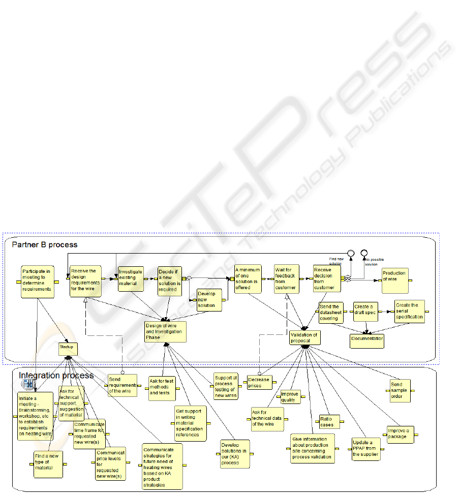
as the “Integration process” (See fig. 1). The dotted
arrows in the figure mark directly visible
interactions between the collaborating partners.
Several potential collaboration areas are indicated
through the relationships towards “Design of wire
and investigation phase” and “Validation of
proposal”. When the initial modelling session were
analysed and revised several activities in the
integration process model were considered as
Partner A specific and were removed. Instead model
elements that capture the collaboration between the
partners were added to the “integration process
model”. For semantic reasons we change the label
“integration process model” to connector view,
which denotes the part of the model that contains the
elements that constitute the collaboration.
Typical collaboration elements added to the
connector view are “Communicate strategies for
future need of heating wires based on Partner A
product strategies” and “Decide on type of project”.
In the latter case a choice between several short term
projects or a long term project “Develop new wire
technology” has to be taken (see fig. 2).
The specific activities that were removed from the
connector view are still of interest since they are
considered to support the collaboration elements in
the connector view for partner A.
The steps that followed were to:
Identify and relate information objects the
collaboration elements in the connector view;
Identify relationships between the elements in
the connector view and the respective partners
enterprise models;
Figure 1: The initial models for Partner B and the integration process model from the first modelling session.
TOWARDS A METHODOLOGY FOR MODELLING INTEROPERABILITY BETWEEN COLLABORATING
ENTERPRISES
335
Figure 2: Some the of collaboration elements in the connector view.
Figure 3: Part of the more mature enterprise model, with the relationships connecting from the collaboration element “Meet
to communicate requirements and decide on test methods” in the connector view.
Identify systems in use and documents/reports
generated by these systems and relate them to
the identified information objects.
The information objects are of mutual interest for
communication between the collaborating partners.
The elements in the connector view were not
directly related to tasks in the already established
models, since the established models are not easily
changeable and they (at least for partner B in this
case) do not have the same scope. Instead specific
supporting objects were captured for both
collaborating partners and were used for connecting
to the elements in the connector view. For partner A
the supporting objects were related to the previously
made models. The resulting model showing objects
related to one of the collaboration elements is shown
in fig 3.
4 TOWARDS A THEORY FOR
THE METHODOLOGY
During our modelling work we observed what parts
of the model that is important to develop as well as a
suitable order to develop the model in. This section
will summarise these observations. The connector
view has a central role in our work for describing the
collaboration between the partners. By using the
connector view it is possible to capture the elements
that establish the collaboration without the need to
modify existing enterprise models at any partner,
e.g. to avoid alignment of the partners enterprise
models in accordance with one specific partner. The
connector view that was established in our use case
ICEIS 2008 - International Conference on Enterprise Information Systems
336

is an example of how to instantiate such a view.
Previous experience from enterprise modelling
enables a focused modelling of the collaboration,
and a careful design of the collaboration elements.
Initially the concept “supporting objects” were
not elaborated. Our intention was to connect the
elements in the connector view with the enterprise
models of the collaborating partners. However we
found that it was necessary to capture the activities
at each partner that trigger the collaboration
elements in the connector view, and that these
activities were not always previously modelled. It is
also relevant to note that this introduces a level of
indirection in the modelling process. The connector
view need not directly depend on previously
determined enterprise models, when performing the
modelling. It is also important when revising
established previous models of relevance for the
collaboration to be sensitive for capturing potential
supporting objects. We can therefore speak of a
supporting view containing supporting objects
relating to the elements in the connector view.
In general the connector view may include the
collaboration between any numbers of collaborating
partners, not only two as in our use case. Each
collaborating partner will have their supporting
view. The connector view will act as the interface
through which the supporting views establish the
collaboration. As mentioned previously the elements
in the connector view are transient, they occur only
when an object in a supporting view trigger them. A
generalization of our experiences from the use case
is found in table 1 where we define the connector
viewpoint and describe a draft methodology for how
to generate a view from the viewpoint. The
methodology draft is divided in four stages,
numbered 1 to 4, each containing one or several
steps, given lower case letters a, b, c etc. The steps
on each stage can be worked on in parallel, and
possibly with iterations between the stages, to add
gained knowledge.
Table 1: Definition of the connector viewpoint.
The connector viewpoint is an integrative viewpoint on different enterprise models exposing the intersection of
these models including:
Objectives of the collaboration between the enterprises in question;
Overlapping processes or tasks;
Information shared or exchanged in these processes;
Resources involved in the overlapping processes or supporting the collaboration, like IT-systems or machinery;
Roles involved in the overlapping processes or tasks and – if required their competences.
A view based on the connector viewpoint may include collaboration elements, which identify subjects of
organizational or technical change (transient nature) when the collaboration is implemented. These elements are not
owned by any of the collaborating partners, and may correspond towards supporting objects.
Stage Step Methodology description
1 a Model goals and problems. It is important to find out from each partner what goals they want
to meet with the system integration and what the problems are in meeting these goals.
1 b Identify existing partner models reflecting the information usage. These can be the existing
enterprise models that are relevant for the case to be modelled at the specific partner.
1 c Identify collaboration elements in the connector view. E.g. how to connect tasks belonging to
different collaborating partners, decisions to be taken, exchange of certain information etc.
2 Identify information necessary for collaboration elements in the connector view. Identified
information objects are related to the collaboration elements in the connector view, (see 4b).
3 a Identify supporting objects that relate to the collaboration elements. These are extensions of
existing partner models that are relevant tasks or other objects in the enterprise for supporting
the communication through the collaboration elements in the connector view.
3 b Identify resources connected to supporting objects. Such as: roles, documents and systems as
sources for information.
4 a Relate collaboration elements through the supporting objects to the partner models.
Collaboration elements are related to supporting objects and supporting objects to objects in the
partner models.
4 b Operationalise the connector view. Describe information usage in connector view. This
includes defining the rules for how the information should be interoperable. It may include
such things as: How terminology matches between systems, triggering mechanisms for
connecting and exchanging information etc. In this step a re-evaluation of the initially stated
goals and problems should be done in order to really focus on what is important when setting
up the functionality of the connector view.
TOWARDS A METHODOLOGY FOR MODELLING INTEROPERABILITY BETWEEN COLLABORATING
ENTERPRISES
337

5 CONCLUSIONS AND FUTURE
WORK
In this paper we have described a collaboration
study between two companies in a networked
organisation. The main contribution is the connector
viewpoint and the identified methodological steps
for how to construct a connector view based on the
connector viewpoint. To model the collaboration in
a separate view gives several advantages:
Existing models for the involved companies
need not to be changed, in the initial stages;
Stakeholders have a natural place to relate
collaborative elements;
It is not necessary to align existing enterprise
models according to one specific partner.
The connector viewpoint may be regarded as a
supplement to the ODP viewpoints for the purpose
of defining the collaboration between partners in an
extended enterprise. Using the connector viewpoint
and the supporting objects, and establishing the
correspondences with the views generated from
viewpoints in RM-ODP, it is possible to understand
how to achieve interoperability between existing
systems located at collaborating partners.
In this study we have done the modelling
between the partners completely open. This is not
always possible. The connector view may however
address the problem with managing sensitive
information. The connector view itself need not
include any sensitive information, whereas the
supporting objects may do so. Since supporting
objects are owned by one specific partner they need
not to be revealed to other partners. Interfacing
between the collaborating partners is handled
through the collaborating elements in the connector
view. Describing the interfaces is therefore an
important part. It should (or may) include rules for
how to determine when, where and to whom the
hidden information can and should be exposed.
Since the results presented are based on a single
use case further work is needed to validate and
refine the proposed methodology in additional
industrial use cases. It is also necessary to explore
more thoroughly how to operationalise the connector
view.
ACKNOWLEDGEMENTS
We want to thank Michael Jüch, Elektrisola
Eckenhagen, and Johanna Ernsth, Kongsberg
Automotive. There help has been invaluable for
carrying out the study.
REFERENCES
Chen, D. and G. Doumeingts (2003). "European Initiatives
to Develop Interoperability of Enterprise Applications
- Basic Concepts, Frameworks and Roadmap." Annual
Reviews in Control 27: 153 - 162.
IEEE (1990). Standard Computer Dictionary: A
Compilation of IEEE Standard
Computer Glossaries. New York.
Ziegler, P. and K. R. Dittrich (2007). Data Integration -
Problems, Approaches, and Perspectives. Conceptual
Modelling in Information Systems Engineering. J.
Krogstie, A. L. Opdahl and S. Brinkkemper, Springer
ISO/IEC (2007). IEEE Std 1471-2000 Recommended
Practice for Architectural Description of Software-
Intensive Systems. ISO/IEC 42010. IEEE: 24.
Putman, J. R. (2001). Architecting with RM-ODP,
Prentice Hall, ISBN 0-13-019116-7
ISO/IEC (2000). ISO/IEC JTC1/SC7/WG17, ISO/IEC
15414|ITU-T Recommendation X.911, Initial
Committee draft; Information Technology-Open
Distributed Processing-Reference Model-Enterprise
Language. CD 15414.
Stirna, J., A. Persson, et al. (2007). Participative
Enterprise Modeling: Experiences and
Recommendations. 19th Intl Conference inAdvanced
Information Systems Engineering, CAiSE 2007.
Trondheim, Springer.
J. A. Bubenko jr, A. Persson, et al. (2001). User
Guide of the Knowledge Management Approach
Using Enterprise Knowledge Patterns, IST Programme
project Hypermedia and Pattern Based Knowledge
Management for Smart Organisations, KTH, Sweden,
(2001) http://www.dsv.su.se/~js/ekd_user_guide.html
Szegheo, O. and S. A. Petersen (2000). "Extended
Enterprise Engineering—A Model-Based
Framework." Concurrent Engineering 8(1): 32-39.
ICEIS 2008 - International Conference on Enterprise Information Systems
338
