
WWW++
Adding
Why to What, When and Where
Paris Pennesi, Mark Harrison
University of Cambridge, Distributed Information and Automation Laboratory and the Auto-ID Lab, U.K.
Chaithanya Rao
Indian Institute of Technology, India
Chien Yaw Wong, Srilakshmi Sivala
RedBite Solutions Ltd., U.K.
Keywords:
Context aware systems, rfid middleware, business process, business context addition.
Abstract:
RFID technology can be used to its fullest potential only with software to supplement the hardware with
powerful capabilities for data capture, filtering, counting and storage. The EPCglobal Network architecture
encourages minimizing the amount of business logic embedded in the tags, readers and middleware. This
creates the need for a Business Logic Layer above the event filtering layer that enhances basic observation
events with business context - i.e. in addition to the (what, when, where) information about an observation,
it adds context information about why the object was there. The purpose of this project is to develop an
implementation of the Business Logic Layer. This application accepts observation event data (e.g. from
the Application Level Events (ALE) standard interface), enriches them with business context and provides
these enriched events to a repository of business-level events (e.g. via the EPC Information Services (EPCIS)
capture interface). The strength of the application lies in the automatic addition of business context. It is quick
and easy to adapt any business process to the framework suggested and equally easy to reconfigure it if the
business process is changed. A sample application has been developed for a business scenario in the retail
sector.
1 INTRODUCTION
Automatic Identification (Auto-ID) technologies such
as Radio-Frequency Identification (RFID) and bar-
codes, combined with architectures (such as the EPC
Network) for processing and exchange of event data,
provide plenty of data and create the opportunity for
an information rich business environment. One of
the main challenges to achieve an information rich
business environment is to link event data automat-
ically created by the EPC Network infrastructure to
the Enterprise Information System, and to contextual-
ize those data into the business process. The ultimate
objective is to infer the business semantics from the
automatic collection of data.
To achieve this objective we need to fill the gap
between the EPC Network and the Enterprise Infor-
mation System. The idea is to create a methodology
which automatically detects the business logic from
the data and links them in the context of the business
process. Ideally, we want to have an adaptive mech-
anism to keep the system running despite changes in
the business process.
The main objective of this paper is to develop
a methodology and a sample application that would
process the observation events (e.g. output from the
ALE interface) and infer business context from the
unique IDs (EPCs), timestamp and reader location be-
fore putting each event into an EPC Information Ser-
vice (EPCIS) repository. We want to add the ‘why’ to
the ‘what’, ‘when’ and ‘where’, dimensions already
present in an observation event from the Application
Level Events (ALE) layer.
Our main contribution is a mechanism that links
data from the ALE component of the EPC Network,
to the business process. That mechanism is highly and
304
Pennesi P., Harrison M., Rao C., Yaw Wong C. and Sivala S. (2008).
WWW++ - Adding Why to What, When and Where.
In Proceedings of the Tenth International Conference on Enterprise Information Systems - DISI, pages 304-309
DOI: 10.5220/0001710403040309
Copyright
c
SciTePress
easily configurable to accommodate different busi-
ness process and to allow changes on time without
requiring IT expertise.
To build our sample application we use input from
the SMART project. SMART (Intelligent Integra-
tion of Supply Chain Processes and Consumer Ser-
vices based on Unique Product Identification in a
Networked Business Environment) is a EU funded
project looking at possible ways of extracting maxi-
mum benefits from a full scale deployment of RFID
technology. The SMART project plans to exploit
unique identification and automatic process monitor-
ing to improve decision making within the retail sec-
tor. The top level goals of the SMART project can be
listed as
• Dynamic pricing
• Promotion Management
• Shelf Replenishment
2 BUSINESS SCENARIO
To illustrate our methodology we focus, without loss
of generality, on a particular business scenario. The
business scenario considered is that of a retailer who
receives stocks from a distribution centre and stores
products in a backroom. The backroom has prede-
fined areas for holding products found to be non-
sellable due to expiry, damage or other reasons as also
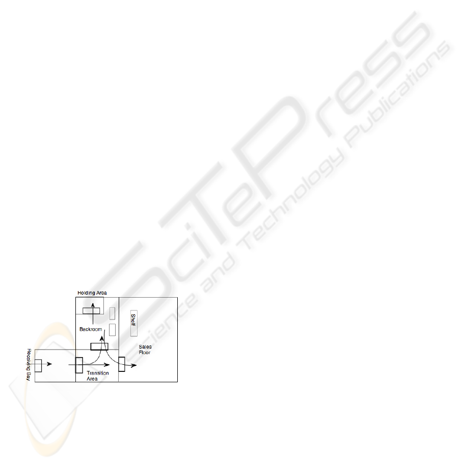
the ones returned by customers. Fig. 1 shows the floor
plan of a hypothetical retailer.
Figure 1: Floor plan of a retailer.
The flow of events at this retailer can be traced as be-
low:
• The Retailer receives an advance shipmment
notice indicating the dispatch of the requested
goods. This transaction includes the unique iden-
tifiers (EPCs) of the goods being shipped.
• The goods are received through the receiving bay
within the receiving area.
• Initial test on the integrity of the product and ex-
istence of tags might be carried out using a hand-
held reader
• It is then taken through the sales transition area,
where it now has two possible destinations:
– The Sales Floor: this might be to meet the ur-
gent requirement for replenishment of stocks
on the sales floor
– The Backroom: the Backroom is the storage
area as well as the holdings area for damaged
goods and goods to be returned.
• In the Backroom , the product might go to the
Holding area. The product might be held back
here for various reasons such as damage, no
matching pedigree etc.
• If the product is perfect with no flaws, it is likely
to be stored on the storage shelves
• The products on the storage shelf might be moved
to the sales floor at a later time or might be moved
to the holding area if they expire during their stor-
age on the shelf.
• The products in the holding area might then be
returned to the manufacturer or the distributor.
The purpose of choosing the above mentioned struc-
ture of the Shop floor or the flow as mentioned above
is to cover almost all possible business steps and dis-
positions available as a part of an EPCglobal vocab-
ulary that has so far been defined by members of the
Fast Moving Consumer Goods sector.
3 METHODOLOGY
Before describing our methodology, we need to
define the Business Logic context. The Business
Logic/Semantics referred to in this report are states or
qualifiers associated with a group of EPCs or a group
of objects of a given EPC class that give more infor-
mation about why those objects were seen by a reader
at a specific location. The business semantics used in
this project can be listed as below
• Business Step is a vocabulary whose elements de-
note steps in business processes. An example is an
identifier that denotes “shipping”. The business
step field of an event specifies the business context
of an event: what business process step was taking
place that caused the event to be captured (EPC-
Global, b)?
• Disposition is a vocabulary whose elements de-
note a business state of an object. An example
is an identifier that denotes “available for sale”.
WWW++ - Adding Why to What, When and Where
305
The disposition field of an event specifies the busi-
ness condition of the event’s objects, subsequent
to the event. The disposition is assumed to hold
true until another event indicates a change of dis-
position. Intervening events that do not specify a
disposition field have no effect on the presumed
disposition of the object (EPCGlobal, b).
• The Action type says how an event relates to
the lifecycle of the entity being described. For
example, Aggregation Event is used to capture
events related to physical aggregations of objects,
such as cases aggregated to a pallet. Through-
out its life, the pallet load participates in many
business process steps, each of which may gen-
erate an EPCIS event. The action field of each
event says how the aggregation itself has changed
during the event: have objects been added to
the aggregation, have objects been removed from
the aggregation, or has the aggregation simply
been observed without change to its membership?
The Action type is an enumerated type having
three possible values namely ADD, OBSERVE
and DELETE. For more details check out EPCIS
standards (EPCGlobal, b).
To link data to the business process we use the au-
tomata framework. An automaton is a model of be-
havior for a system composed of a finite number of
states, transitions between those states, and actions
( (Hopcroft et al., 2007)).
More formally, an automaton is a sixtuple
(E, X, x
0
, F, Γ, X
m
), where:
• E is the event set (a finite non empty set of sym-
bols).
• X is a finite non empty set of states.
• x
0
is an initial state, an element of S.
• F is the state transition function: F : X x E → X
• Γ is the active event function defined as Γ : X →
2
E
• X
m
is the set of final states, a (possibly empty) sub-
set of S.
The finite non empty set of states, X
m
, is defined as an
ordered pair of two values namely Business step and
Business disposition. It could be extended to include
more fields than the ones listed. These are the ones
specified in the EPCglobal data standards for event
data. All the states are referred to by number in the
transition table or the state diagram. The state table
listing the business steps and dispositions for the busi-
ness scenario discussed in this section is shown in Ta-
ble 1.
It is not necessary to use the same definition of
states, although it is advisable to make use of standard
Table 1: State Definition Table.
BizStep BizLogic
- -
shipping in transit
accepting in progress
receiving in progress
- inspecting
receiving sellable accessible
receiving sellable not accessible
- receiving
storing sellable not accessible
storing non sellable expired
storing non sellable recalled
storing non sellable damaged
storing non sellable no pedigree match
storing non sellable other
holding non sellable expired
holding non sellable recalled
holding non sellable damaged
holding non sellable no pedigree match
holding non sellable other
holding returned
Stocking sellable accessible
Picking In progress
Stag Outb non sellable expired
Stag Outb non sellable recalled
Stag Outb non sellable damaged
Stag Outb non sellable no pedigree match
Stag Outb non sellable other
Loading
Sold
Destroying Destroyed
vocabularies for business steps and business disposi-
tions specified by the EPCglobal or by other industry
standards bodies. Note that the initial state x
0
is ‘-1’.
It denotes a wait state. When a uniquely identifiable
object (or EPC) is seen for the first time, its initial
state is set to ‘-1’. When it is seen once again, its ex-
istence is confirmed and it is assigned a state number.
There could be additional wait states which have not
been included. The set of the wait states and the set
X
m
define the set X.
The event set E consists of the following:
• Tags being read at a location.(e.g. 1000 EPCs
were observed at the receiving bay)
• Transaction events.(An advance shipment notice
is sent listing the EPCs that are being shipped)
• Timed checking events(e.g. Every day a check
is performed if a product has exceeded its expiry
date)
• Checking events about the integrity of the pro-
ducte.g. Pedigree checks
A list of possible event sets for the business scenario
in discussion is given in Table 2.
ICEIS 2008 - International Conference on Enterprise Information Systems
306
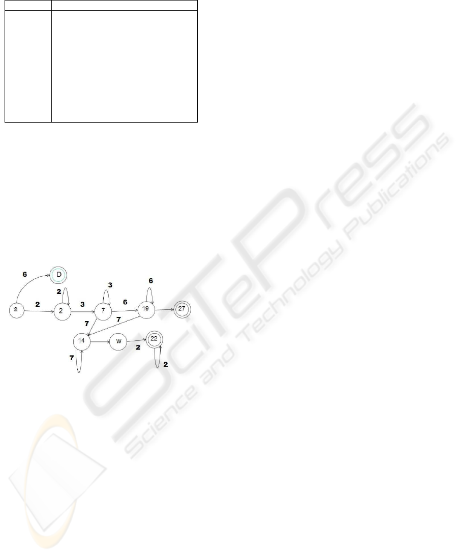
Table 2: Event Set.
Event No Description
1 Advance Shipment notice is sent
2 Product seen at receiving bay
3 Product seen at Transition Area door
4 Inspection on handheld device
5 Product seen at Backroom door
6 Product seen at Salesfloor door
7 Recall demanded on a product
8 Product seen at Holding area door
9 Product seen on Backroom shelf
10 Product seen on sales floor shelf
11 Product seen at POS
The transition diagram in Fig. 2 includes the states in
discussion and for each given state, the correspond-
ing transitions for each of the event sets. Note for
our case, the consistent and required transitions are
very small considered to the total possible transitions.
Therefore the sample state transition diagram for the
case in consideration shows only the essential and
meaningful transitions. All others are inconsistent
and have to be handled using wait states, doubtful
states and flagged-off danger states.
Figure 2: State transition diagram.
The numbers encircled denote the state numbers and
their description can be checked from the State Def-
inition Table, Table 1. The numbers on the arrows
denote the event set and their description is as pro-
vided in Table 2. The states marked with 2 circles are
marked states. As an example, let us focus on state
‘14’, a wait state. If an object is being returned to
the distributor through the receiving bay and passes
through the backroom door, then there is not much
significance with the products crossing the backroom
and they could be confirmed to be leaving the facility
only when they are seen through the transition area
door. Wait states can be used generously and EP-
CIS events linked with them are recorded without any
business context.
A specific state not included in the state defini-
tion list can be used as the flagged-off state to denote
any inconsistencies like a product that should have be
been returned being seen on the sales floor. All doubt-
ful cases may be dealt with using a default wait state
that just records the event.
4 WWW++ APPLICATION
4.1 Architecture
For the implementation of our sample application we
use as a starting point the Accada project (Accada, ).
Accada is an open source software RFID prototyping
platform that implements the EPC Network specifi-
cations. Accada provides implementations which are
platform independent under GPL. The requisite mod-
ules of Accada which have been used in the project
are listed below:
• ALE(Application Level Events): The ALE soft-
ware has two main components, namely the filter-
ing and counting server and the client. All events
from the physical reader are directed towards the
ALE server. The server then filters the reads based
on event definitions and logical reader classifica-
tions. It then prepares an XML report that can be
displayed online or sent to a TCP address speci-
fied in a client’s subscription. The report format
and the event cycle specifications need to be set by
a system administrator. These specifications can
be uploaded using the ALE client. It gives the user
the ability to set event cycle start and stop times,
as well as the periodicity of reporting. Event cy-
cles can also be triggered by other actions. The
specification is set using XML files and the corre-
sponding schema can be found in the ALE stan-
dard version 1.0 (EPCGlobal, a)
• EPCIS Repository: EPC Information Services
(EPCIS) is a standard for exchange and retrieval
of business-level events. An EPCIS event repos-
itory can store reads from radio frequency identi-
fication (RFID) tags and readers, with additional
business context annotations per event.
• Capture Client: The capture client is an interface
that pushes data into an EPCIS repository. It ac-
cepts manual input of data including the EPCs and
business semantics.
• Query Client: The query client queries the EPCIS
repository for events that match specified query
criteria, which may include the EPC, time, busi-
ness disposition, transaction id etc.
The Accada implementation of the EPCIS capture ap-
plication requires manual input and does not interface
with the ALE. When all parts of the Accada software
WWW++ - Adding Why to What, When and Where
307
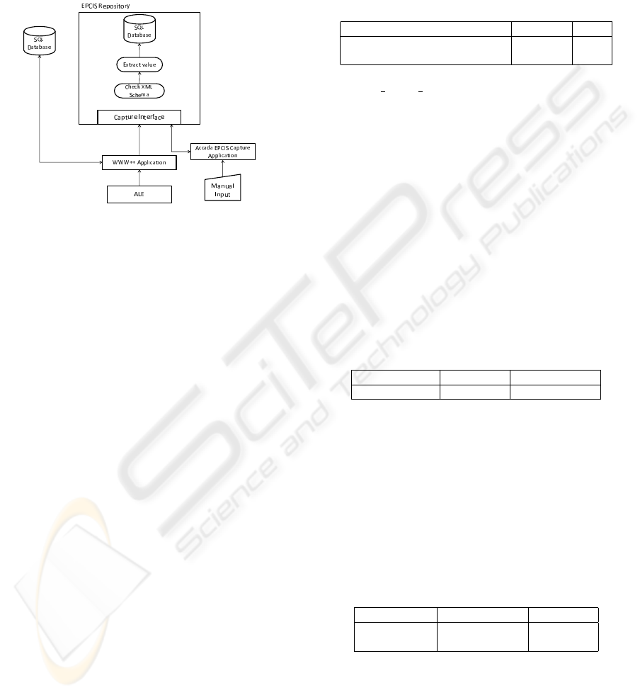
are put together there still lies an application gap be-
tween the output of the ALE layer and the input to the
EPCIS repository via the capture interface. Though a
capture client is available, it requires manual input of
meaning as well as the basic event data like the EPCs
and the event time.
Figure 3: Structure.
Fig. 3 shows the architecture of the system. WWW++
refers to the application in discussion. WWW++ as-
sumes a position in between the ALE and the EP-
CIS repository acting as a controller which decides
the business semantics to be added. This decision is
based on the automaton described in Sec. 3. The ap-
plication does not post the data itself but uses the EP-
CIS repository server’s capture interface.
The ALE layer sends its reports in XML format
according to a standard schema ((EPCGlobal, a)).
The WWW++ acts as a tcp server listening at a given
port address. On receiving the report the WWW++
application uses JAXB to unmarshal the document
and extract the three essential values (what, when and
where). The ‘where’ is not explicitly mentioned but a
spec name is included which indicates the specifica-
tion that generated the report. This specification cor-
responds to a logical reader location. If the ‘what’ is
a list of EPCs, then object events are noted.
The business context dection algorithm depends
on the level of tagging. The best possible results can
be achieved with the use of item level tagging. This
makes it possible to isolate an object at each stage
of its life and hence associate a State to it. In this
case an automaton is used. The automaton is defined
by its elements. All the elements are stored as SQL
tables, some of which are loaded at the beginning of
the application while others are referred to throughout
the operation of the application.
A state definition table similar to the one in Ta-
ble 1 is stored in SQL tables and loaded at the be-
ginning of the application.The application maintains
a State table as shown in Table 3. It maintains a field
called a flag that can take binary values 0 or 1
0 means Consistency.
1 means an Inconsistency
Table 3: The State Table.
EPC State No Flag
urn:epc:tag:gid-96:10.50.1000 2 0
urn:epc:tag:gid-96:10.50.1001 3 1
The Spec Event Link table is used to link the Spec-
Name with a reader location. The reports from the
ALE layer contain the name of the specification that
was used to create the report. Since the ALE report
is generated for the logical readers listed in the spec-
ification file, the SpecName corresponds to a location
marked by the intersection of a few readers.
Manual events have to be entered through a cap-
ture application like Accada’s implementation for the
EPCIS capture interface. Any other data, for exam-
ple ERP data or barcode data can be handled by the
WWW++ application provided that the data is refor-
matted to conform to the XML schema provided for
ALE reports
The structure of the table is as follows
Table 4: Spec Event Link Table.
SpecName ReadPoint Event Number
ReceivingBay x:y:z:t.h.k 5
Table 3 defines the event set for finite state machine.
The transition function can be described by the
state diagram or by the transition table. The transition
table consists of three fields, namely Present State,
Event Number and Next State. A sample transition
table is shown in Table 5. It is stored as an SQL ta-
ble that is loaded at the start of the application. The
transition table should handle all possible cases i.e.
number of states x number of events.
Table 5: Transition Table.
Present State Event Number Next State
-1 1 0
0 2 4
4.2 Configuration
Configuration of the SQL tables is very essential to
the proper working of the application. First a list of
all the logical readers must be made. Then an event
ICEIS 2008 - International Conference on Enterprise Information Systems
308

should be associated with it. Once the spec files for
the logical readers are uploaded they should all be
subscribed to by the client machine that is running the
WWW++ application on an appropriate port address.
A State definition table should be made, as shown in
previous section. It is also necessary to create the ta-
ble that links spec names with events. in the appendix,
we provide SQL scripts to generate the tables and link
them. The transition table is the most important table
and utmost care must be taken while configuring it.
When a new event is added, then for all the existing
states the transition for the given state should be de-
fined. Triggers have been associated to perform this
task. However, the trigger initializes the table with the
default ‘-1’ (start state). It is the responsibility of the
system administrator to have a well defined transition
table and to update the transition table when events
are added. Also when a new state is added then all the
transitions from that state to all existing events must
be added. This is also implemented using SQL trig-
gers, although the default value of ‘-1’ should be up-
dated to the required value. The state definition table
must be ordered in an ascending order according to
the state numbers. Also the first two states (denoted
‘-2’ and ‘-1’) are reserved for the flagging state and
the start state. The User may define his own states
starting from ‘0’.
5 CONCLUSIONS
In this paper we proposed a new methodology to inte-
grate information and event from the enterprise infor-
mation system and the ALE component of the EPC
Network, adding business context to them before to
feed the EPCIS Repository, to provide an informa-
tion rich business environment. The methodology is
based on automata theory and a sample application
for a specific business scenario has been provided.
The ability to easily configure it for any business
process is one of its strengths. It is also equally easy
to reconfigure for further changes in the process.
ACKNOWLEDGEMENTS
The work has been partially supported by the Euro-
pean Commission trough the SMART, “Intelligent In-
tegration of Supply Chain Processes and Consumer
Services based on Unique Product Identification in a
Networked Business Environment” (European Sixth
Framework Project ST5034957STP).
REFERENCES
Accada. http://www.accada.org.
EPCGlobal. Application level events (ale).
http://www.EPCglobalinc.org/standards/Application
Level Event ALE Standard Version 1.0.pdf.
EPCGlobal. Epc information services.
http://www.EPCglobalinc.org/standards/EPCglobal
EPCIS Ratified Standard 12April 2007 V1.0.pdf.
Hopcroft, J., Motwani, R., and J.D. Ullman, J. (2007). In-
troduction to Automata Theory, Languages, and Com-
putation, Third Edition. Addison-Wesley.
WWW++ - Adding Why to What, When and Where
309
