
QUALITY IMPROVEMENT OF WORKFLOW DIAGRAMS BASED
ON PASSBACK FLOW CONSISTENCY
Osamu Takaki, Takahiro Seino, Izumi Takeuti, Noriaki Izumi and Koichi Takahashi
Research Center for Verification and Semantics, Information Technology Research Institute
National Institute of Advanced Industrial Science and Technology, Japan
Keywords:
Formal Verification, Requirement Analysis, UML Activity Diagrams, Workflow Diagrams.
Abstract:
Passback flows are a kind of flows which appear as replays of operations in a workflow diagram. In order to
consider consistency of a workflow diagram and to verify the consistency, it needs to deal with passback flows
as special ones. In this paper, we formalize a passback flow in a workflow diagram with only graph theoretical
properties of the workflow diagram, and we give an algorithm detecting and removing all passback flows in
a workflow diagram. Furthermore, with the algorithm, we extend consistency properties of the structure and
life cycles of evidences over an acyclic workflow diagram into those over a general workflow diagram. Our
methodology enables us to improve quality of a workflow diagram with loops.
1 INTRODUCTION
Model Driven Development (MDD) is a development
framework, which has been proposed as a method to
fill the semantical gap between processes of a devel-
opment and to resolve the problem of irrevocableness
of the processes. The main feature of MDD is to an-
alyze business and operations, to make models of the
analysis results, and to employ the models through
the whole development processes. It is important in
MDD to separate and to associate requirement and
system models explicitly.
Actually, for developments of large scale informa-
tion systems in MDD, it is very important that users
can take the initiative in formulating and verifying
specifications in requirement analyses. Here , “users”
mean office staffs who work with such information
systems. They do not know details of the information
systems, but the whole business using the information
systems clearly. In fact, they are not familiar with re-
quirement specifications, which are formulated based
on formal approach or even UML. So, it needs user-
friendly and well-formed frameworks of requirement
analyses to promote user-centered model driven de-
velopments.
From the standpoint of the significance above,
a workflow diagram has been employed as a user-
friendly diagram, which expresses flows of business
operations. A workflow diagram is very similar to
a UML activity diagram with several informal infor-
mations such as evidences (cf. (Object Management
Group (OMG), 2000), (Eriksson and Penker, 2000)).
Here, an “evidence” is an evidence-document used in
operations of a workflow diagram. However, a work-
flow diagram is easier for users to compose than such
a UML activity diagram.
In order to deal with user-friendly diagrams in for-
mal methodology, several frameworks (Takaki et al.,
2007a) (Takaki et al., 2007b) have been proposed,
which give workflow diagrams and design support
tools “AIST Workflow Verifier” (AWV) and “AIST
Workflow Editor” (AWE) for requirement analyses.
AWV is a verification tool of workflow diagrams,
and AWE is an integrated environment for workflow
diagrams, which has AWV as a plug-in tool for it.
AWV verifies consistency properties of syntax, struc-
ture and life cycles of evidences of a workflow dia-
gram. Here, a “life cycle” of an evidence is a series
of states of the evidence between the point where the
evidence appears for the first time and the point where
the evidence is removed.
Almost all business with information systems are
to operate evidences and data in database systems.
So, the quality of a workflow diagram strongly de-
351
Takaki O., Seino T., Takeuti I., Izumi N. and Takahashi K. (2008).
QUALITY IMPROVEMENT OF WORKFLOW DIAGRAMS BASED ON PASSBACK FLOW CONSISTENCY.
In Proceedings of the Tenth International Conference on Enterprise Information Systems - ISAS, pages 351-359
DOI: 10.5220/0001709703510359
Copyright
c
SciTePress
pends on whether or not life cycles of evidences in the
workflow diagram are consistent. In fact, we have im-
proved workflow diagrams by verifying consistency
of life cycles of evidences of them (cf. (Takaki et al.,
2007b)).
The papers above gave an algorithm which veri-
fies consistency of structure and evidence life cycles
of an acyclic workflow diagram, and AWV has been
developed based on the algorithm. However, it is not
very clear to deal with a cyclic workflow diagram.
Some loops in a workflow diagram have flows
called “passback flows”, and others do not. Passback
flows are a kind of flows which go backward from
lower streams to upper streams. For example, the flow
labeled “no” in the figure 1 is a passback flow. Such
a passback flow often appears as a replay of opera-
tions in a workflow diagram. We will give detailed
explanation of them in Section 3. For verification of
consistency of evidence life cycles of a workflow, one
haveto deal with passback flows exceptionally. More-
over, one can not apply the algorithm in the previous
papers which verifies consistency of structure of an
acyclic workflowdiagram to a workflowdiagram with
passback flows.
In order to clarify the properties of a cyclic work-
flow diagram, in this paper, we formalize a passback
flow in a workflow diagram with only graph theo-
retical properties of the workflow diagram, and we
give an algorithm detecting and removing all pass-
back flows. Although the workflow diagram obtained
by removing passback flows is only an approximation
of the original one, the approximation is sufficient
to verify consistency of life cycles of evidences of
an original workflow diagram. This assertion comes
from our observation of workflow diagrams which
have been composed and used for real system devel-
opments.
Furthermore, by using the algorithm of remov-
ing passback flows, we extend consistency properties
of the structure and life cycles of evidences over an
acyclic workflow diagram into those over a general
workflow diagram, which may be cyclic. In order
to apply the verification algorithm for acyclic work-
flow diagrams to verify consistency of cyclic work-
flow diagrams, AWV calculate an acyclic workflow
diagram as an approximation of the cyclic workflow
diagram. By using the extended consistency proper-
ties above, one becomes not to need to remove loops
without passback flows, and one can easily improve
the verification algorithm for acyclic workflow dia-
grams so that one can verify consistency of structure
and life cycles of evidences in general workflow dia-
grams more correctly. As a result, the methodology
above enables us to deal with workflow diagrams in-
cluding loops in a strict manner, and hence, it helps us
to improvequality of them. In Section 2, we introduce
a syntax of workflow diagrams. In Section 3, we ex-
plain passback flows and formalize them with graph
theoretical properties of workflow diagrams. We also
give an algorithm which removes all passback flows
in a workflow diagram. In Section 4, by using the
algorithm above, we extend consistency properties
of the structure and life cycles of evidences over an
acyclic workflow diagram into those over a general
workflow diagram. In Section 5, by using the defini-
tions in Section 4, we explain a way to improve AWV.
2 WORKFLOW DIAGRAM
A workflow diagram is a diagram expressing flows of
operations which compose a work. In this section,
we explain workflow diagrams, especially syntax of
workflow diagrams. Before explanation of the syntax,
we show an example of a workflow diagram.
2.1 Illustration of a Workflow Diagram
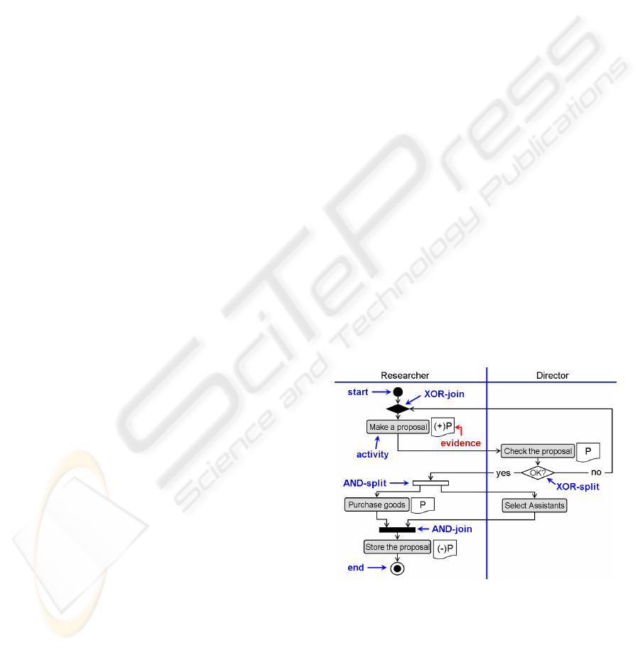
The workflow diagram in the figure 1 describes a
work of planning and preparing for a research. In the
diagram, rectangles denote operations needed for the
work and figures directly beside rest angles denote ev-
idences (evidence documents) used on the operations
denoted by the rectangles. For example, the rectangle
“Make a proposal” has the evidence “(+)P”.
Figure 1: Example of a workflow diagram.
In the figure 1, first a researcher composes a pro-
posal of a research, and then a director checks the
proposal. If the proposal passes the checking, then
the proposal is returned to the researcher and he/she
purchases goods. On the other hand, the director
select assistants for the research, after the proposal
passes the director’s checking. Finally, the proposal is
ICEIS 2008 - International Conference on Enterprise Information Systems
352

stored by the researcher, after both of the purchasing
of goods and selecting of assistants are completed. If
the proposal does not pass the checking, then the pro-
posal is returned to the researcher and he/she remakes
the proposal. We call such a replay of the operation a
“passback”. Passbacks are often described in a work-
flow diagram.
2.2 Syntax of Workflow Diagrams
Here we explain our syntax of workflow diagrams.
For simplicity, we omit a portion of the syntax. For
example, we omit the definition of “actors” such as
“researcher” or “director” in the figure 1, which de-
note ones who perform operations in a workflow dia-
gram. Although the concept of actors is important, it
is not of technical importance for this paper.
Workflows. A workflow diagram is defined to be a
directed graph, which consists of nodes such as
operations in the figure 1 and flows expressed as
arrows.
Sources and Targets. Every flow has the source and
target: the source is the starting node of the flow
and the target is the destination node of it. For
example, for the flow labeled as “yes” in the figure
1, the source of the flow is the XOR-split node
labeled as “OK?” and the target of it is the AND-
split node expressed as the slim rectangle.
Incoming Flows and Outgoing Flows. For a node
N, a flow with target N is called an incoming flow
of N and a flow with source N is called an outgo-
ing flow of N. For example, the flow labeled as
“yes” is the incoming flow of the AND-split node
as well as an outgoing flow of the node labeled as
“OK?”.
Types of Nodes. There are several types of nodes in
workflow diagrams, which are listed up in the ta-
ble 1. In the table 1, “IF” and “OF” express the
Table 1: Types of Nodes in Workflows.
type labeled? IF OF
start no 0 1
end no 1 0
XOR-split yes 1 ≧ 2
AND-split no 1 ≧ 2
XOR-join no ≧ 2 1
AND-join no ≧ 2 1
activity yes 1 1
number of incoming flows and that of outgoing
flows of a node, respectively. Moreover, “≧ 2”
means that the number is more than or equal to 2.
For simplicity, we omit several types of nodes
which are not of technical importance for this pa-
per.
Evidences. An activity node may have a list of evi-
dences. Any node other than an activity node does
not have evidences. We define the syntax of evi-
dences in a later section.
Additional Conditions
1. Every workflow diagram has at least one start
node.
2. For a workflow diagram W and a node N in W,
there exists at least one path
1
from a start node
to N. In particular, a workflow diagram is con-
nected.
2.3 Role of Workflow Components
Although we give no precise explanation of semantics
of workflow diagrams in this paper, we explain how
to use components of workflow diagrams roughly.
• A flow means an order between two operations or
events.
• An activity node means an operation by its label.
• A start node and an end node mean a starting point
and an ending point of a workflow, respectively.
• An XOR-split node means a branch whose label
denotes the conditional statement. Moreover, an
outgoing flow of an XOR-split node is labeled
by an answer to the conditional statement of the
XOR-split node.
• An XOR-join node means a confluence of paths
which are essentially divided by some branches.
When a job stream
2
arrives at an XOR-join node
M via an incoming flow of M, M immediately
sends the job to (the target of) the outgoing flow
of M. We assume that multiple job streams can
not arrive at any XOR-join node through multiple
incoming flows of the XOR-join node simultane-
ously.
• An AND-split node means a parallel branch.
When a job stream arrives at an AND-split F via
an incoming flow of F, F immediately sends the
job to all outgoing flows of F simultaneously.
1
In this paper, a path is a sequence ( f
1
, . . . , f
n
) of flows
in a workflow diagram such that the target of f
i
is the same
as the source of f
i+1
for every i = 1, . . . , n−1.
2
A job stream in this paper means a “current work” in a
workflow diagram. In the theory of Petri Net, what we call
a job stream is called a “token”.
QUALITY IMPROVEMENT OF WORKFLOW DIAGRAMS BASED ON PASSBACK FLOW CONSISTENCY
353

• An AND-join node means a point which waits
jobs arriving at the point via all incoming flows of
the point. Only when jobs arrive at an AND-join
via all incoming flows of the AND-join, it sends
the jobs to its outgoing flow.
2.4 Evidence
In Section 2.2, we explained that some activity node
have a list of evidences. In this section, we explain
evidences in detail. An evidence which an activity
node has means a document which is used in the
operation expressed by the activity node. Each ev-
idence is expressed as a triple (e, created, removed),
which consists of a label e and boolean values created
and removed. For simplicity, each evidence E =
(e, created, removed) is abbreviated, as follows (see
the figure 1).
• If created = false and removed = false, then we
abbreviate E as “e”.
• If created = false and removed = true, then we
abbreviate E as “(−)e”.
• If created = true and removed = false, then we
abbreviate E as “(+)e”.
• If created = true and removed = true, then we ab-
breviate E as “(+)(−)e”.
For a workflow diagram, every evidence E is de-
scribed directly beside just one activity node A, and
it means that E is an evidence document used at the
operation denoted by A. Moreover, if E has the (+)-
mark, then it means that E occurs in A for the first
time in the workflow diagram. On the other hand, if
E has the (−)-mark, then it means that E is removed
(stored or dumped) in A.
Remark. In what follows, we often identify an ev-
idence E in a workflow diagram with the evidence
document which is expressed by (the label of) E, and
the evidence document (or the label of an evidence) is
just called an “evidence”.
A life cycle of an evidence in a workflow dia-
gram is a sequence of evidence sharing the same la-
bel, which are in activity nodes between a node in
which the evidence occurs for the first time and one
in which the evidence is stored or dumped. For ex-
ample, in the figure 1, there is a life cycle of a “pro-
posal”, which is the sequence of evidences consisting
of (+)P in the activity node “Make a proposal”, P in
the activity node “Check the proposal”, P in the activ-
ity node “Purchase goods”, and (−)P in the activity
node “Store the proposal”.
Consistency of a life cycle of an evidence over a
workflow diagram means that there is no case where
the evidence occurs without (+)-mark, it is removed
without (−)-mark, or it increases or decreases.
In the later section, we will define a life cycle of
an evidence in a workflow diagram and its consistency
precisely.
3 PASSBACK FLOWS AND THE
REMOVING ALGORITHM
The papers (Takaki et al., 2007a) and (Takaki
et al., 2007b) have developed two algorithms named
“GAPSG” and “EVA”. GAPSG abstracts certain sub-
graphs of an acyclic workflow diagram and verifies
consistency of the structure of the workflow diagram.
On the other hand, EVA verifies consistency of life
cycles of evidences of an acyclic workflow diagram,
by using subgraphs of the workflow diagram obtained
by GAPSG. The main purpose of this paper is to give
a definition of passback flows and an algorithm which
removes all passback flows from a workflow diagram.
By virtue of them, it is possible to extend the algo-
rithms to those for general workflow diagrams.
We investigated about 460 workflow diagrams,
which were formulated in real developments of large
information systems (cf. (Takaki et al., 2007b)),
and we obtained the following results about loops in
workflow diagrams.
Observation 1. Most loops in a workflow diagram
contain flows which we call “passback flows”.
Observation 2. The change of evidences during a
passback flow is not described in the workflow di-
agram. In other words, even if there is some in-
consistency between the evidences on the source
node of (the first flow of) a path containing a pass-
back flow and those on the target node of (the last
flow of) the path, one should not regard it as an
error.
We first explain Observation 1. Most loops in a
workflow diagram do not express primary streams of
operationsin the workflowdiagram, but replays of op-
erations for some problems. Passback flows are con-
tained in such loops in a workflow diagram. For ex-
ample, the workflow diagram in the figure 1 has one
loop, which contains a flow labeled “no”. The flow is
a passback flow which expresses howto replay the op-
erations in the workflow diagram if the proposal does
not passed the checking by the director.
Here we explain Observation 2. In principle, ev-
idences on each node in a workflow diagram is de-
scribed only when a job stream arrived at the point for
the first time. For example, the activity node “Make
a proposal” in the figure 1 has an evidence “(+)P”,
ICEIS 2008 - International Conference on Enterprise Information Systems
354
which is information described at the first time when
the job stream arrives at the activity node from the
start node. The evidence “(+)P” is not what is de-
scribed in the case where a job stream arrives at the
activity node via the passback flow “no”. Therefore,
we should not consider that the evidence P in the ac-
tivity node “Check the proposal” changes to the evi-
dence (+)P in the activity node “Make the proposal”
via the flow “no”.
The observations above indicate that a verification
algorithm should not output inconsistency between
evidences on the source node of a path containing a
passback flow and the target node of the path as an
error.
One may take the stance that refuses to deal with
passback flows as special ones. That is, it is possible
to take the stance to accept a workflow diagram only
in cases where the workflow diagram has no incon-
sistency between evidences on the source node of a
path containing a passback flow and those on the tar-
get node of the path. However, in this paper, we take
the stance to deal with passback flows as special ones.
There is another reason why it is useful to consider
passback flows in a workflow diagram. In the later
sections, we will show that one can extend GAPSG
and EVA for a cyclic workflow diagram in which no
loop contains any passback flow. Thus, in order to ap-
ply GAPSG and EVA to a cyclic one, one only have
to deal with loops containing passback flows in an ap-
propriate manner.
3.1 Definition of Passback Flows
In this section, we formalize passback flows in a
workflow diagram, by using only graph theoretical
properties of the workflow diagram.
A path ( f
1
, . . . , f
n
) in a workflow diagram W sat-
isfying the following properties is called a lariat path.
1. The source of f
1
is a start node in W.
2. The target of f
n
is the source of one of f
2
, . . . , f
n
.
3. For each i and j with i 6= j, f
i
and f
j
do not share
the same source.
The last flow f
n
of a lariat path σ := ( f
1
, . . . , f
n
) is
called the tail of σ.
A path ( f
1
, . . . , f
n
) in a workflow diagramW satis-
fying the following properties is called a directly end-
ing path.
1. The source of f
1
is a start node in W.
2. The target of f
n
is an end node in W.
3. For each i and j with i 6= j, f
i
and f
j
do not share
the same source.
Lemma. Every flow f in a workflow diagram W sat-
isfies one of the following properties.
1. f is contained in a directly ending path in W.
2. f does not satisfy the property 1 above, but f is
the tail of a lariat path in W.
3. f does not satisfy the property 1 nor 2 above, but
f is contained in a lariat path in W.
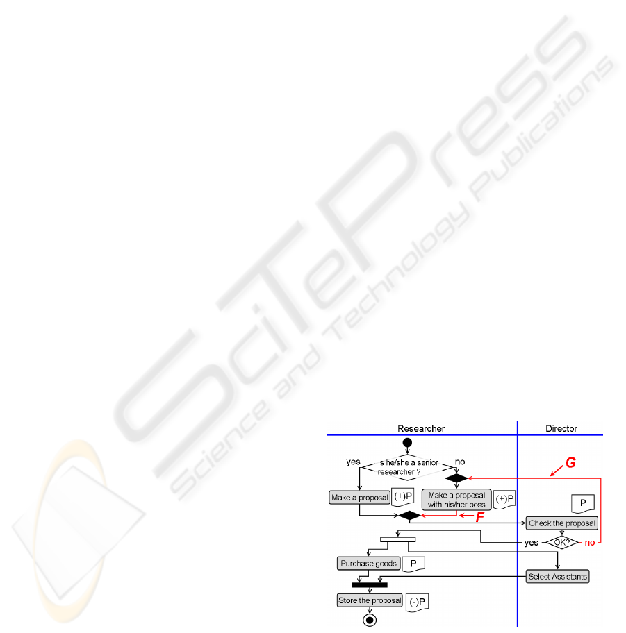
For example, the flow F in the figure 2 satisfies the
property 1 above. Information about F is described as
F is considered a member of a directly ending path.
In fact, the source node “Make a proposal with his/her
boss” of F has an evidence (+)P, which means a state
of the evidence document when a job stream gets to
the first XOR-split node from the start node and it gets
to an XOR-join node from the XOR-split node via the
flow labeled “no” and it finally gets to the node above
from the XOR-join node.
On the other hand, the flow G in the figure 2 sat-
isfies the property 2 above. Then, G is considered the
tail of a lariat path, and evidences which change cor-
responding to G are not described.
In the followingtwo paragraphs, we consider what
a passback flow is.
First, a passback flow heads in the opposite direc-
tion to a primary job stream and reaches such a job
stream. Therefore, a passback flow is the tail of a lar-
iat path.
Next, consider a flow contained in some directly
ending path. Then, the flow is considered a member
of a directly ending path, and the change of evidences
during the flow is described in the workflow diagram,
even if it is the tail of a lariat path. Therefore, the flow
is not considered a passback flow.
Figure 2: Modified workflow diagram.
By virtue of the discussion above, we can formal-
ize passback flows, as follows. A flow f in aworkflow
diagram W is called a passback flow if f is the tail of
QUALITY IMPROVEMENT OF WORKFLOW DIAGRAMS BASED ON PASSBACK FLOW CONSISTENCY
355

a lariat path in W and there is no directly ending path
in W which contains f.
The definition of passback flows is equivalent to
the property 2 in the lemma above.
For example, in the figure 2, G is a passback flow,
while F is not even though F is the tail of a lariat path.
3.2 Algorithm Removing Passback
Flows
Here we define an algorithm which translates a work-
flow diagram W into some workflow diagram(s) with
no passback flow, as follows.
1. Detect all flows in W and record tails t
1
, . . . , t
n
of
all lariat paths in W.
2. Detect all directly ending paths and let p
1
, . . . , p
m
be tails each of which is not contained in any di-
rectly ending path. These tails are passback flows
in W.
3. Replace targets T
1
, . . . , T
m
of p
1
, . . . , p
m
by new
end nodes E
1
, . . . , E
m
, respectively. These end
nodes are called additional end nodes. Note that
the number of incoming flows of each T
i
de-
creases.
4. Execute the following operations corresponding
to the number of incoming flows of each T
i
. (Note
that each T
i
is an XOR-join or AND-join node.)
(a) If T
i
has more than or equal to two incoming
flows, then leave T
i
as it is.
(b) If T
i
has just one incoming flow, then replace
the target of the incoming flow by the target of
the outgoing flow of T
i
, and then remove T
i
as
well as the outgoing flow of T
i
.
(c) If T
i
has no incoming flow, then replace the
source of the outgoing flow of T
i
by a new start
node and remove T
i
. The new start node is
called a additional start node.
We call the algorithm above RAPF (Removing Al-
gorithm of Passback Flows), and express the set of
workflow diagrams obtained from a workflow dia-
gram W by RAPF in RAPF(W).
RAPF makes no new lariat path. Moreover, any
flow in a directly ending path does not become not
to be contained in any directly ending path by RAPF.
Thus, we have the following proposition.
Proposition. RAPF translates a workflow diagram W
into RAPF(W), each element in which is a workflow
diagram with no passback flow.
RAPF may output multiple workflow diagrams.
We show an example in the figure 3. However, in
Figure 3: RAPF may divide a workflow into multiple work-
flows.
most cases, RAPF does not divide a workflow dia-
gram into multiple ones. For example, we have the
following property.
Proposition. For a workflow diagram W, if every
node in W has a path from it to an end node in W,
then RAPF(W) is a singleton set.
4 CONSISTENCY OF GENERAL
WORKFLOW DIAGRAMS
In this paper, we extend consistency property of the
structure and that of evidence life cycles over an
acyclic workflow diagram to those over a general
workflow diagram, by using the algorithm RAPF.
4.1 Consistency of Structure of a
General Workflow Diagram
The papers (Takaki et al., 2007b) and (Takaki et al.,
2007a) define subgraphs called “trace graphs” dia-
gram and consistency property called “phenomena in-
dependence” of the structure over an acyclic work-
flow diagram. Phenomena independence is a desired
property of a workflow diagram, since it helps the
workflow diagram to have good readability. More-
over, abstracting trace graphs from an acyclic work-
flow diagram W and verifying phenomena indepen-
dence ofW are utilized for verification of consistency
of evidence life cycles ofW, which we will explain in
Section 4.2.
Here we define trace graphs and phenomena in-
dependence of a general workflow diagram. These
definitions are defined similarly to the previous ones
except new definitions use RAPF.
For a workflow diagram W, a subgraph U of an
element V of RAPF(W) is called a trace graph of W
if every node N in U satisfies the following properties.
1. If N is an XOR-split node, then U has just one
outgoing flow of N in V and the incoming flow of
N.
ICEIS 2008 - International Conference on Enterprise Information Systems
356

2. If N is an XOR-join node, then U has just one
incoming flow of N in V and the outgoing flow of
N.
3. Otherwise, U has all incoming and outgoing flows
of N in V.
A workflow diagram W is said to be phenomena
independent if, for each elementV of RAPF(W), each
flow in V is contained in some trace graph of W.
If W has no passback flow, then the new defini-
tions of trace graphs and phenomena independence
of W are the same as the previous definitions, since
RAPF(W) = {W} in this case. Therefore, the new
definitions are natural extensions of the previous def-
initions, respectively.
The algorithm of abstracting trace graphs and ver-
ifying phenomena independence over general work-
flow diagrams can be obtained in the similar way to
that in (Takaki et al., 2007a) except for using RAPF
defined above.
4.2 Consistency of Life Cycles of
Evidences in a General Workflow
Diagram
In (Takaki et al., 2007b) and (Takaki et al., 2007a),
consistency of life cycles of evidences of an acyclic
workflow diagram is defined. Here we define the con-
sistency for a general workflow diagram in the similar
way to the previous definition.
A workflow diagram W is said to be consistent for
life cycles of evidences if W satisfies the following
properties 1 and 2.
1. W is phenomena independent.
2. For each trace graph V of W, for each activity
node A in V, and for each evidence E in A, there
exists just one path L := (A
1
−−→
f
1
··· −−→
f
n−1
A
n
)
satisfying the following properties.
(a) A
1
and A
n
are activity nodes.
(b) Every activity node in L contains E.
(c) If there is a path from a non-additional start
node to A
1
, then E of A
1
has the (+)-mark.
(d) Any activity node except A
1
does not have the
(+)-mark in E
(e) If there is a path from A
n
to a non-additional
end node, then A
n
has the (−)-mark in E.
(f) Any activity node except A
n
does not have the
(−)-mark in E.
(g) L contains A.
According to the technique in (Takaki et al.,
2007b), one verifies consistency for life cycles of ev-
idences of an acyclic workflow diagram by checking
Figure 4: AWV on Microsoft
R
Visio
R
.
the local properties of evidences in the workflow dia-
gram. In a similar way to that in (Takaki et al., 2007b),
one can define local properties of evidences over a
general workflow diagram, by which one can verify
consistency for life cycles of evidences of the work-
flow diagram.
5 DISCUSSION
5.1 Improvement of AWV
AWV is introduced in (Takaki et al., 2007b) and
(Takaki et al., 2007a) as a verification tool of work-
flow diagrams. It has a workflow diagram or multiple
workflow diagrams as input data, and returns a list of
counter-examples of consistency for life cycles of ev-
idences of the input data. The figure 4 is a snapshot
of AWV, which uses Microsoft
R
Visio
R
as the plat-
form.
AWV already has a function which translates
cyclic workflow diagrams into those with no passback
flow. However, the previous papers have not yet ex-
plained what passback flows are and how to remove
them. Therefore, this paper is the first one which ex-
plains passback flows and how to remove them pre-
cisely.
Moreover, there are some cyclic workflow dia-
grams with no passback flow. AWV can not verify
consistency for life cycles of evidences of such work-
flow diagrams, since AWV first tries to translate such
workflow diagrams to acyclic ones and then AWV
stops verification for them if AWV can not remove
all loops in them by removing all passback flows in
them.
However, one can improve AWV by using the al-
gorithms in Section 4, and obtain a new verification
tool “AWV2”, which can verify workflow diagrams
even if they have some loops and no passback flow.
QUALITY IMPROVEMENT OF WORKFLOW DIAGRAMS BASED ON PASSBACK FLOW CONSISTENCY
357

On other words, one can obtain AWV2 from AWV,
which satisfies the following properties.
1. For every general workflow diagram W, AWV2
can determine whether W is phenomena indepen-
dent or not.
2. If W is phenomena independent, then AWV2 re-
turns at least one counter-example of consistency
for life cycles of evidences of W if W is not con-
sistent for life cycles of evidences, and vise versa.
Especially, W is consistent for life cycles of evi-
dences if and only if AWV2 returns the empty list.
5.2 Related Work
The research of passback flows in this paper started
with an observation of workflow designers’ excep-
tional treatments of a special kind of flows, that we
call passback flows. So far as we know, there seems
to have been few researches of special kinds of flows
such as passback flows from the point of view of ver-
ification for workflow diagrams. For example, there
have been a lot of researches of verification of consis-
tency of structure of workflow diagrams (cf. (van der
Aalst, 1997), (Sadiq and Orlowska, 1997), (van der
Aalst, 1998), (Sadiq and Orlowska, 2000), (Verbeek
et al., 2001), (Lin et al., 2002), (van der Aalst et al.,
2002), (Kiepuszewski et al., 2003), (Liu and Kumar,
2005) or (Takaki et al., 2007a)). Moreover, there
also have been several researches of document-centric
workflow diagrams such as (Dourish et al., 2000)
(Botha and Eloff, 2001), (Krishnan et al., 2002) and
(Wang and Kumar, 2005). However, these researches
above do not consider exceptional flows such as pass-
back flows.
Over the last decade, there have been developed a
lot of workflow languages such as BPEL4WS (BPEL)
(Andrews et al., 2003), XPDL (Workflow Manage-
ment Coalition (WfMC), 2002), EPC (Keller et al.,
1992) and YAWL (van der Aalst and ter Hofstede,
2005). Our syntax is developed in order to describe
human workflows and it has a similar structure to
XPDL. The main difference between our syntax and
XPDL is that a workflow diagram in our syntax may
have multiple start nodes and end nodes.
Phenomena independence defined in Section 4.1
is a consistency property of structure of workflow dia-
grams, that is weaker than “correctness” of workflow
diagrams defined in (Sadiq and Orlowska, 2000) or
(van der Aalst et al., 2002). We use RAPF to trans-
late a general workflow diagram into acyclic work-
flow diagrams and to verify phenomena independence
of them by using algorithms in (Takaki et al., 2007a).
6 CONCLUSIONS
In order to clarify the properties of a cyclic workflow
diagram, in this paper, we give a definition of pass-
back flows in a workflow diagram and an algorithm
RAPF of removing all passback flows in a workflow
diagram. Furthermore, by using RAPF, we extend
definitions of trace graphs, phenomena independence
and consistency for life cycles of evidences over an
acyclic workflow diagram into those over a general
workflow diagram.
By virtue of RAPF and new definitions above, one
can obtain algorithms of abstracting trace graphs and
verifying phenomena independence and consistency
for life cycles of evidences over general workflow di-
agrams in the similar ways to those in (Takaki et al.,
2007b) and (Takaki et al., 2007b), and improve AWV
in the policy explained in Section 5.
REFERENCES
Andrews, T., Curbera, F., Dholakia, H., Goland, Y., Klein,
J., Leymann, F., Liu, K., Roller, D., Smith, D., Thatte,
S., Trickovic, I., and Weerawarana, S. (2003). Busi-
ness Process Execusion Language for Web Services,
Version 1.1. Technical report, BEA Systems, Inter-
national Business Machines Corporation, Microsoft
Corporation.
Botha, R. A. and Eloff, J. H. P. (2001). Access control
in document-centric workflow systems an agent-based
approach. Computers and Security, 20(6):525–532.
Dourish, P., Edwards, K. K., Lamarca, A., Lamping, J., Pe-
tersen, K., Salisbury, M., Terry, D. B., and Thornton,
J. (2000). Extending document management systems
with user-specific active properties. ACM Transac-
tions on Information Systems, 18(2):140–170.
Eriksson, H. E. and Penker, N. (2000). Business Modeling
With UML. John Wiley & Sons, Inc.
Keller, G., Nuttgens, M., and Scheer, A. W. (1992). Se-
mantische Prozessmodellierung auf der Grundlage
Ereignisgesteuerter Prozessketten (EPK). Technical
Report 89, Institut fur Wirtschaftsinformatik Saar-
brucken, Saarbrucken, Germany.
Kiepuszewski, B., ter Hofstede, A. H. M., and van der Aalst,
W. M. P. (2003). Fundamentals of control flow in
workflows. Acta Informatica, 39(3):143–209.
Krishnan, R., Munaga, L., and Karlapalem, K. (2002).
Xdoc-wfms: A framework for document centric
workflow management system. In Conceptual Model-
ing for New Information Systems Technologies, LNCS
2465, pages 348–362. Springer.
Lin, H., Zhao, Z., Li, H., and Chen, Z. (2002). A novel
graph reduction algorithm to identify structural con-
flicts. In Proceedings of the 35th Annual Hawaii In-
ternational Conference on System Science (HICSS).
IEEE Computer Society Press.
ICEIS 2008 - International Conference on Enterprise Information Systems
358

Liu, R. and Kumar, A. (2005). An analysis and taxonomy
of unstructured workflows. In Proceedings of 3rd In-
ternational Conference on Business Process Manage-
ment (BPM), LNCS 3649, pages 268–284. Springer.
Object Management Group (OMG) (2000). OMG Unified
Modeling Language Specification, Version 1.3.
Sadiq, W. and Orlowska, M. E. (1997). On correctness is-
sues in conceptual modeling of workflows. In Pro-
ceedings of the 5th European Conference on Informa-
tion Systems (ECIS), pages 943–964.
Sadiq, W. and Orlowska, M. E. (2000). Analysing process
models using graph reduction techniques. Information
Systems, 25(2):117–134.
Takaki, O., Seino, T., Takeuti, I., Izumi, N., and Taka-
hashi, K. (2007a). Algorithms verifying phenomena
independency and abstracting phenomena subgraphs
of uml activity diagrams. In Software Engineering
Saizensen 2007, pages 153–164. Kindaikagaku-sha
(in Japanese).
Takaki, O., Seino, T., Takeuti, I., Izumi, N., and Takahashi,
K. (2007b). Verification algorithm of evidence life
cycles in extended uml activity diagrams. In Pro-
ceedings of The 2nd International Conference on Soft-
ware Engineering Advances. IEEE Computer Society
Press.
van der Aalst, W. M. P. (1997). Verification of workflow
nets. In Application and Theory of Petri Nets 1997,
LNCS 1248, pages 407–426. Springer.
van der Aalst, W. M. P. (1998). The application of petri nets
to workflow management. The Journal of Circuits,
Systems and Computers, 8(1):21–66.
van der Aalst, W. M. P., Hirnschall, A., and Verbeek, H.
M. W. (2002). An alternative way to analyze workflow
graphs. In Proceedings of the 14th International Con-
ference on Advanced Information Systems Engineer-
ing (CAiSE), LNCS 2348, pages 535–552. Springer.
van der Aalst, W. M. P. and ter Hofstede, A. H. M. (2005).
Yawl: Yet another workflow language. Information
Systems, 30(4):245–275.
Verbeek, H. M. W., Basten, T., and van der Aalst, W. M. P.
(2001). Diagnosing workflow processes using woflan.
The Computer Journal, 44(4):246–279.
Wang, J. and Kumar, A. (2005). A framework for
document-driven workflow systems. In Proceedings
of 3rd International Conference on Business Process
Management (BPM), LNCS 3649, pages 285–301.
Springer.
Workflow Management Coalition (WfMC) (2002). Work-
flow Management Coalition Workflow Standard:
Workflow Process Definition Interface - XML Process
Definition Language (XPDL). (WfMC-TC-1025),
Technical report, Workflow Management Coalition,
Lighthouse Point, Florida, USA.
QUALITY IMPROVEMENT OF WORKFLOW DIAGRAMS BASED ON PASSBACK FLOW CONSISTENCY
359
