
A GOAL METHOD FOR CONCEPTUAL DATA WAREHOUSE
DESIGN
Leopoldo Zepeda, Ramon Zatarain
Departamento de Sistemas, Tecnologico de Culiacan, Juan de Dios Batiz, Sinaloa, Mexico
Matilde Celma
Departamento de Sistemas y Computacion, Universidad Politecnica de Valencia, Valencia, Spain
Keywords: Data Warehouse, Goal model, Multidimensional schema, Conceptual design.
Abstract: In this paper, we present a goal-oriented method for DW analysis requirements. This paper shows how goal
modelling contributes to a logical scoping and analysis of the application domain to elicit the information
requirements, from which the conceptual multidimensional schema is derived.
1 INTRODUCTION
In this paper, we present a goal-oriented method for
conceptual DW design (a process driven method).
This method starts from the set of goals of multiple
stakeholders of the DW. Then we capture these
goals in a goal model. This goal model contributes
to an analysis of the application domain to elicit an
initial set of information requirements, from which
the conceptual multidimensional schema is derived.
We propose three steps to define the goal model:
1) Goal model definition.- In this step the strategic
goals are identified and a Goal Refinement Tree
(GRT) is build. 2) Goal description.- We describe
the set of actions to obtain some goal of the
organization. This description is completed by using
UML Activity Diagrams (OMG). 3) Domain
notation. Initial information requirements are
obtained from each task description. Finally, the
conceptual multidimensional schema is derived from
these requirements. The main contribution of this
work are: 1) A goal model for DW, this model
captures not only what data means but also who
wants them and for what purpose. 2) The
representation of the domain model that describes
the necessary understanding of a part of the real
word and facilitates the communication of the
domain knowledge between developers, end users
and stakeholders. 3) The use of a UML activity
diagrams for the identification of the initial
information requirements. 4) Our approach reduces
the development time of a DW, facilitates managing
the strategic objectives, and allows the designer to
perform the analysis of the goals.
The rest of the paper is organized in four
sections. Section 2, relates the proposed approach to
the state of the art. In Section 3, the design process is
presented. The construction of the conceptual
schema is summarized in Section 4. Finally, in
section 5, we present our conclusions.
2 RELATED WORK
A summary of data warehousing and OLAP
technology and associated research issues on
multidimensional databases can be found in some
articles and books. In (Luján-Mora, S., Trujillo, J.,
Song) the authors presents a UML profile for
conceptual multidimensional modelling, which
represents the principal multidimensional properties
at the conceptual level, such many-to-many
relationships between facts and dimensions, multiple
and alternative path classification hierarchies, and
non strict and complete hierarchies. The Process-
driven approaches described in (Mazon, J-N.,
Trujillo, J., Serrano, M., Piattini) and (M., Giorgine,
P., Rizzi, S. Garzetti, M.) are based on the i*
framework. The requirements are used to build a
conceptual model in a fully process-driven
457
Zepeda L., Zatarain R. and Celma M. (2008).
A GOAL METHOD FOR CONCEPTUAL DATA WAREHOUSE DESIGN.
In Proceedings of the Tenth International Conference on Enterprise Information Systems - DISI, pages 457-460
DOI: 10.5220/0001694304570460
Copyright
c
SciTePress
perspective. In (Paim, F.R.S.) the DW Requirements
definition (DWARF) technique is presented. The
authors adapt traditional requirements engineering
process to propose a methodological approach for
requirements definition of DWs. In general, we
found very few contributions in the literature
specifically concerned with goal-process
approaches. The approaches presented in (Mazon, J-
N., Trujillo, J., Serrano, piattini, M.) and (Giorgine,
P., Rizzi, S. Garzetti, M.) are perhaps the closest to
ours, in particular as far as the goal model of our
method is concerned. The main difference is that we
provide a standard way for the identification and the
representation of the information requirements.
3 DESIGN PROCESS
The aim of this phase is to capture the information
requirements to be kept in the DW. This phase deals
with the identification of the strategic goals of the
organization, decisions that can be taken to achieve
these goals and the information requirements needed
for decision making.
Our approach proposes the construction of a goal
model. It uses the concepts of goal and task of the i*
conceptual framework (Lamsweerde, A. van.). In
agreement with goal orientation philosophy, our goal
model is built from the strategic goals and tasks that
users must be able to accomplish when interacting
with the DW. Afterwards, the information
requirements will be discovered from these tasks
using UML activity diagram. Finally, the
information requirements will be used for the
construction of the conceptual multidimensional
schema. We propose three steps to define the task
model: 1) Goal Model Definition, 2) Task
description and 3) Identify Domain Notation.
3.1 Step 1. Goal Model Definition
We specify the information requirements of a DW
system by means of a goal model. This model is
build from the strategic goals that the stakeholders
of a DW are interested in analyzing. In a DW
environment, strategic goals represent the main
objectives of the organization. These objectives deal
with the business process to be analyzed but usually
they lack details. A GRT can be used to refine these
strategic goals. For the construction of the GRT, we
take as the starting point, a strategic goal
(Lamsweerde, A. van). From this strategic goal,
goals are obtained following structural refinements.
The refinement, consists of decomposing goals into
sub-goals through an OR/AND relationship. This
refinement of goals can continue until we have tasks
that are tangible.
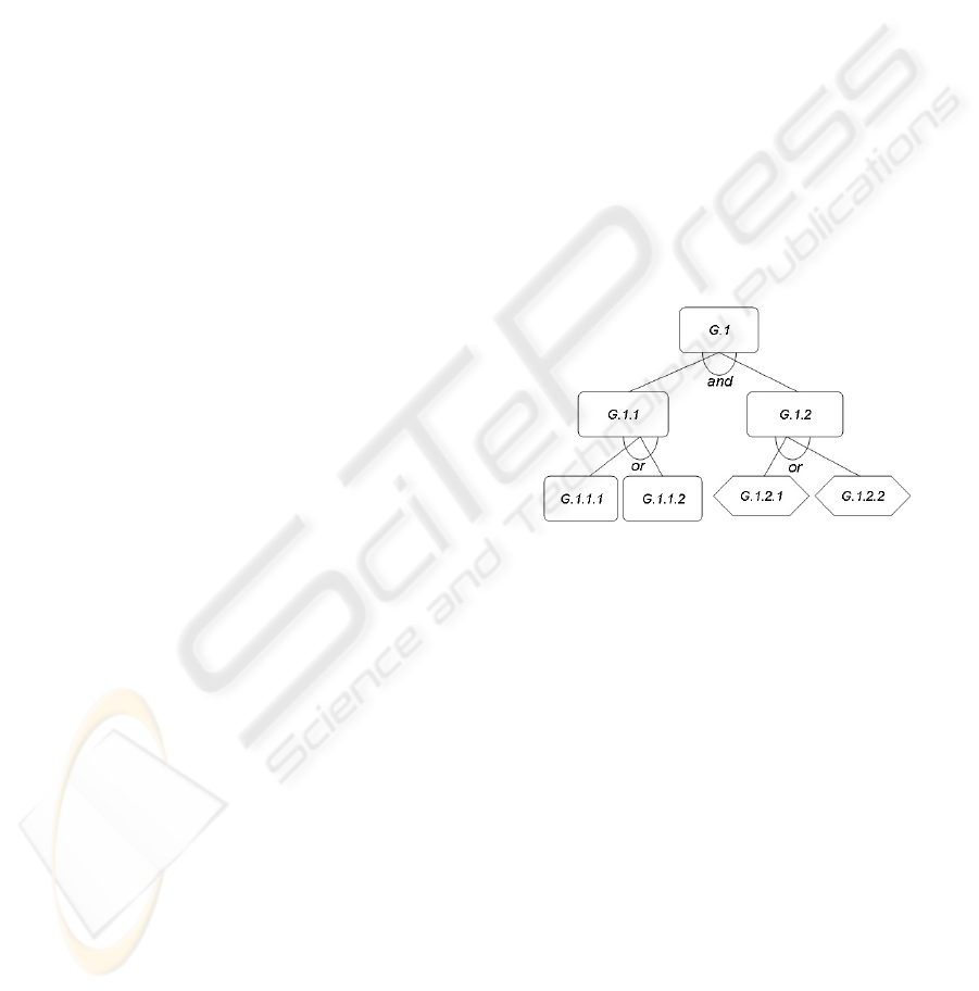
Example. In this section, we provide an example of
our approach. Suppose we are modelling the
strategic goals of a self-service store, such as Wal-
Mart. In our example, one main domain stakeholders
are identified: sales manager and offer manager.
The strategic goals of the sales manager are: G1.-
Increase return on investment and G2.- Increase
customer fidelity. For instance the strategic goal
Increase return on investment may be AND
decomposed into G.1.1.- Increase sales volume and
G1.2.- Increase sales profit. Likewise, increase
sales volume might be OR decomposed into
G.1.1.1.- Increase consumer appeal or G1.1.2.-
Expand market. In our example, at least two well-
established tasks can be to Increase sales profit:
G.1.2.1.- Increase sales price or G.1.2.2.- Lower
production costs. The partial representation of the
goal model is shown in figure 1.
Figure 1:
A partial goal model.
3.2 Step 2. Task Description
During this step, each task of the GRT is related to
the actions that stakeholders consider necessary in
order to satisfy each task. These actions are
formulated in terms of the information required by a
task to be achieved. Similarly to (Valderas, P., Fons,
J., Pelechano V.) for tasks descriptions, we use
UML Activity Diagrams (OMG)). In these
diagrams, we show the actions performed to obtain
some task, indicating the roles that are in charge of
each activity, and the data required and produced by
each activity. Data appear as objects that flow
between activities. We refer to these objects as Data
Objects (DO). We distinguish two different types of
DOs. 1) Output DO: the system provides actors with
information about data. 2) Input DO: the system is
waiting for the user to introduce some data. This
information is taken by the system to correctly
perform a specific action. Figure 2, shows an
activity diagram for the description of the increase
ICEIS 2008 - International Conference on Enterprise Information Systems
458
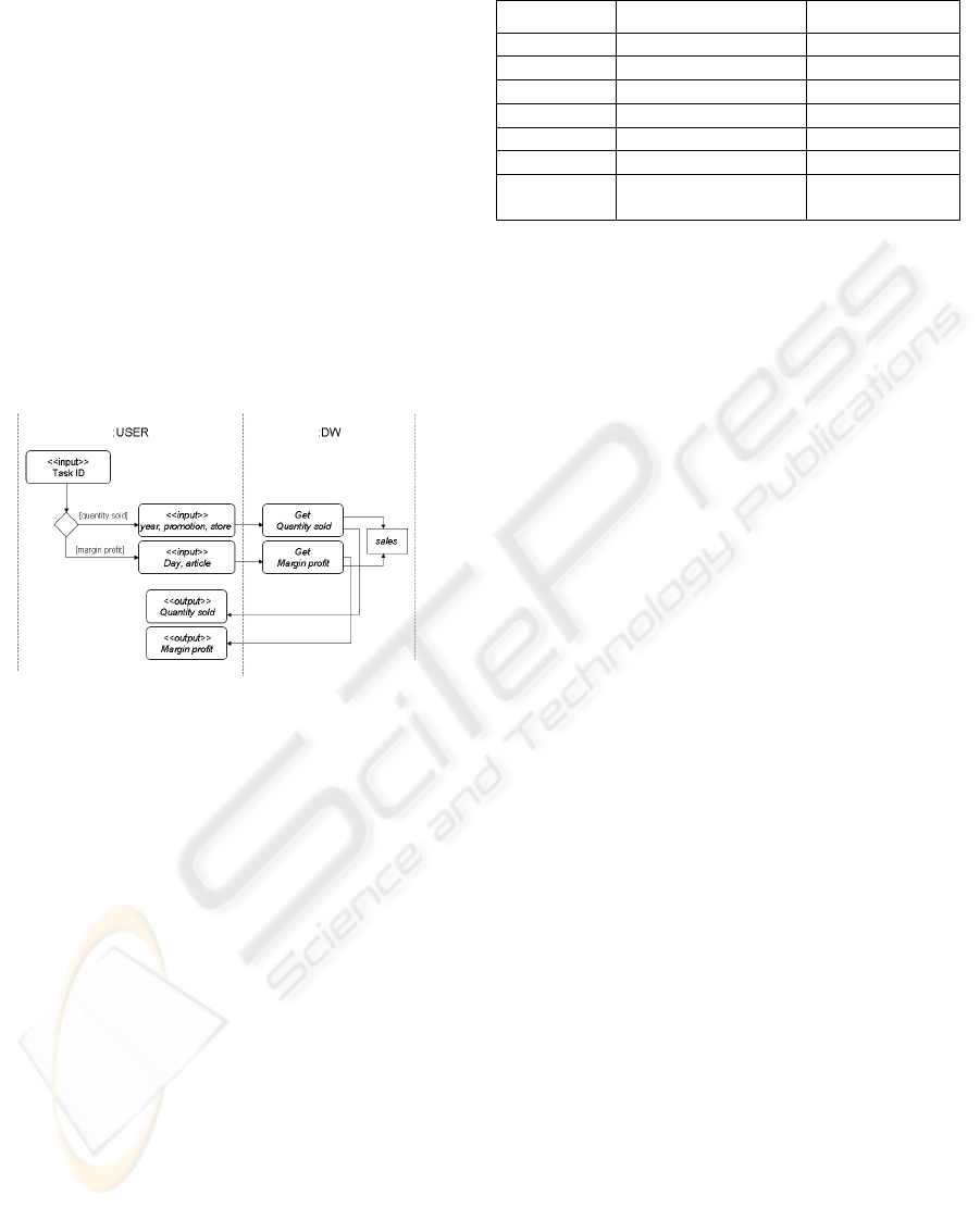
sales price task. This task is related with two
actions: analyze the margin profit and the quantity
sold. The activity diagram starts with the selection of
an individual action. So, for instance if the selected
action is quantity sold, this action, will search
information that matches with the information
provided by the DW user through an Input DO
(year, promotion and store). In order to perform its
purpose, this action needs access to the data-source
sales. (An Entity is considered a data source, if the
operational database is modelled by an Entity-
Relationship schema. If the operational database is
modelled by a Relational schema a Relation is
considered a data source.). Once this action is
finished, the task continues with an Output DO,
where the DW system provides the DW user with
the list of matched information.
Figure 2: Task description.
3.3 Step 3. Identify Domain Notation
In this step, we extract initial information
requirements from the task description. The
extracted information is called domain notation if it
describes a domain concept (Jiang, L., Topaloglou,
T., Borgida, A. Mylopoulos, j). Domain notation,
represents potential data to be stored in the DW.
Well know heuristics for DW design can be applied
here: within the multidimensional model a domain
notation usually corresponds to factors that are
supposed to influence the values of the measures
(dimensions), data descriptors (measures) and data
to be analyzed (facts).
Example. The set of domain notation corresponding
to the UML activity diagram of the figure 2, is
shown in table 1. According to the information
showed in table I, the information that the DW must
store about the increase sales price task is:
promotions, year, day, store, Quantity sold and
Margin profit. This information is related with the
data source sales.
Table 1: Domain notation.
Task
Domain notation Data Object
T1 Promotions Input
T1 Year Input
T1 Store Input
T1 Quantity sold Output
T1 Margin profit Output
T1 Day Input
Data
source
Sales -------
4 FROM REQUIREMENTS TO
CONCEPTUAL DESIGN
Once the domain notation was defined based on
user’s information, it can be interpreted to find the
principal concepts of the multidimensional model:
facts, dimensions, measures, levels and hierarchies.
In particular, the items listed in the Data Object
column are considered as measures and dimensions
levels, while the data source is considered the fact to
be analyzed. Then, the Input DO defines the
variables that may cause changes to measures
(dimension levels) and each Output DO contributes
a measure. The information of the Table I, can be
interpreted as follows: the data source sales details a
fact. The Input DO (promotions, article, year, day
and store) detail the dimensions levels, while the
Output DO (Quantity sold and Margin profit) detail
the measures. During this phase, the measures and
dimension levels must be detailed, where possible in
order to build the conceptual multidimensional
schema. For this, we propose two steps: 1) Measure
definition and 2) Hierarchy and Dimension
definition.
4.1 Step 1. Measure Definition
Measures are normally expressions involving
numerical attributes. As Table 1, shows, we have
obtained for our example two measures (Quantity
sold and Margin profit) that describe the information
that need to be fully analyzed by the user through
the DW system. At this step, it is practical to build a
measure dictionary, which associates each measure
to a mathematical expression. The goal of this
expression is to describe how can be calculated each
measure. Within a process-driven framework, in the
lack of knowledge about the structure of the data
sources, the designer can limit itself just to describe
an achievable way to obtain the expected result of
each measure.
A GOAL METHOD FOR CONCEPTUAL DATA WAREHOUSE DESIGN
459
Example. Referring to our example, the measure
dictionary may be compiled as show in table 2. The
mathematical expression: Sum (quantity *
sales_price) – (quantity * price_cost) describes how
the measure Margin profit can be calculated, at the
same time, from this description come into view
additional information (quantity, sales_price and
price_cost). This information, it is useful for the
phase of ETL process where these attributes must be
mapped, where possible against the operational data
sources.
Table 2: Measure dictionary.
Measure Mathematical Expression
Quantity sold Sum (quantity)
Margin profit
Sum (quantity
*sales_price) – (quantity *
price_cost)
4.2 Step 2. Hierarchy and Dimension
Definition
For the definition of hierarchies, the designer must
identify the existing functional dependencies (FD)
between the levels previously identified.
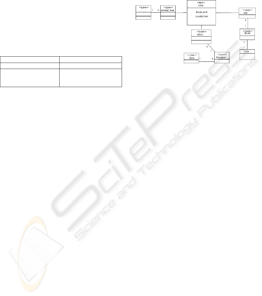
Example. In our example, the Input DOs includes
the promotion, article, store, day and year as
dimension levels. From these levels, is possible to
determine the following FDs: H1) article
Æ
promotion
Æ
store and H2) day
Æ
year. The result
of this activity depends of the experience of the DW
designer and his ability to interact with the domain
experts to capture the dependencies between the
levels. For instance, the DW designer can associate
the level month to the hierarchy H2 (day
Æ
month
Æ
year) also he can assume that H1 corresponds to a
dimension named Store and H2 to a dimension
named Time. The conceptual multidimensional
schema obtained by applying the criteria above is
represented in figure 3.
5 CONCLUSIONS
In this paper, we have presented a goal-oriented
method for the conceptual design of DWs.
Following the goal orientation philosophy, our goal
model is build from the strategic goals of the
stakeholders. First a GRT is specified using the
concepts of the i* framework. Then the description
of each task is performed using UML activity
diagram. From these diagrams, we get the
information requirements for the construction of the
conceptual multidimensional schema. The future
works pretend to extend this proposal with the
intention of adding soft-goals to the goal model in
order to collect nonfunctional requirements.
Figure 3: Conceptual multidimensional schema.
REFERENCES
Giorgine, P., Rizzi, S. Garzetti, M., 2005. Goal-oriented
requirements analysis for data warehouses design. In.
DOLAP 2005, pp. 47-56.
Jiang, L., Topaloglou, T., Borgida, A. Mylopoulos, j.,
2006. Incorporating Goal Analysis in Database
Design: A Case Study from Biological Data
Management. 14th IEEE International Conference on
Requirements Engineering (RE 2006).
Lamsweerde, A. van. 2001. Goal-Oriented Requirements
Engineering: A Guided Tour, Proc. 5º IEEE
International Symposium on Requirements
Engineering, X Toronto, Canadá.
Luján-Mora, S., Trujillo, J., Song, I-Y. 2002. Extending
UML for Multidimensional Modeling, 5th
International Conference on the Unified Modeling
Language (UML 2002), LNCS 2460, pp. 290-304,
2002.
Mazon, J-N., Trujillo, J., Serrano, M., Piattini, M., 2005.
Designing data warehouses: From business
requirement analysis to multidimensional modeling. In
Proc. 1st Int. Workshop on Requirements Engineering
for Business Need and IT Alignment, Paris, France.
Object Management Group (OMG)., 2003. Unified
Modeling Language (UML) Specification Version 2.0
Final Adopted Specification. www.omg.org,.
Paim, F.R.S., Castro, J.B., 2003. DWARF An Approach
for Requirements Definition and Management of Data
Warehouse Systems. 11th IEEE International
Requirements Engineering Conference (RE'03), pp.
75-86, Monterey Bay, California, USA.
Valderas, P., Fons, J., Pelechano V., 2005. Using Task
Descriptions for the Specification of Web Application
Requirements. Workshop en ingeniería de requisitos,
Porto Portugal.
ICEIS 2008 - International Conference on Enterprise Information Systems
460
