
AUTOMATIC GENERATION OF
UML-BASED WEB APPLICATION PROTOTYPES
Shinpei Ogata
Department of electronic engineering and computer science, Graduate School of Engineering
Shibaura Institute of Technology, 307 Fukasaku, Minuma-ku, Saitama-City, Saitama 337-8570, Japan
Saeko Matsuura
Department of Electronic Information Systems, College of Systems Engineering, Shibaura Institute of Technology
307 Fukasaku, Minuma-ku, Saitama-City, Saitama 337-8570, Japan
Keywords: Requirements Analysis, Prototyping for Web Application, UML.
Abstract: The key to success in business system development is to sufficiently elicit user requirements from the
customers and to fully and correctly define the requirements analysis model that meets these requirements.
Prototyping is recognized as an effective software development method that enables customers to confirm
the validity of the requirements analysis model at an early stage of system development. However, the
development process requires guaranteeing consistency between the system model and customer
requirements that arise as a result of the confirmation. This paper proposes a method for the incremental
validation of a Web application wherein a prototype system is automatically generated from a requirements
analysis model based on UML (Unified Modeling Language). This model defines the interaction between a
system and the user, in addition to defining the input/output data. Moreover, the automatic generation tool
of the prototype system enables the developer to confirm the system image incrementally while developing
the requirements analysis model in UML. We discuss the expressiveness of the generated prototype in
comparison with the current group work support tool.
1 INTRODUCTION
The key to success in business system development
is to sufficiently elicit user requirements from
customers and to fully and correctly define the
requirements analysis model that meets these
requirements. Prototyping is recognized as an
effective software development method that enables
customers to confirm the validity of the
requirements analysis model at an early stage of
system development (Onishi and Go, 2002; Davis,
1993; Kotonya and Sommerville, 2000). However,
the development process requires guaranteeing
consistency between the system model and customer
requirements that arise as a result of the
confirmation. We propose a method for supporting
the requirements analysis and validation process
incrementally, based on a requirements analysis
model developed using UML (Unified Modeling
Language) (OMG, 2007; Fowler, 2004) and an
automatic prototype system generation tool. We
have developed a tool that automatically generates a
prototype system for a Web application from the
model that comprises three kinds of UML diagrams.
In order to develop high quality systems suitable for
business application, customers themselves need to
confirm the validity of the business workflow
process and the input/output data. We ensured that
these confirmation items are closely related to the
elements of UML 2.0 diagrams so that the model
can be easily modified according to new customer
requirements that arise as a result of the
confirmation. The automatic generation mechanism
of the prototype system enables the developer to
easily continue to refine the model until the
customer is able to validate it.
The rest of the paper is organized as follows.
Section 2 explains the definition of the requirements
analysis model and the prototype system. Section 3
describes the requirements analysis and validation
244
Ogata S. and Matsuura S. (2008).
AUTOMATIC GENERATION OF UML-BASED WEB APPLICATION PROTOTYPES.
In Proceedings of the Tenth International Conference on Enterprise Information Systems - ISAS, pages 244-251
DOI: 10.5220/0001692702440251
Copyright
c
SciTePress
process in which the developer and the customer
carry out their work. Section 4 explains the design
and implementation of the automatic generation tool
of the prototype system. Section 5 discusses the
result of applying our method to developing the
group work support tool. Section 6 concludes the
paper.
2 REQUIREMENTS ANALYSIS
MODEL AND THE
PROTOTYPE SYSTEM
2.1 Prototype System
The aim of the prototype system is to enable
customers to validate the requirements analysis
model such that it adequately meets their workflow
processes. To develop a high quality system,
customers need to validate the items listed in Table 1
by using the prototype system that is defined in
HTML.
Table 1: Customer’s Confirmation Items.
Categories Items
Business
Workflow
Process
1) What types of services are provided
to the user?
2) How can the user carry out these
services via page transitions?
3) What types of data are required to be
input by the user so as to carry out the
service?
4) What types of data are provided to the
user as a result of the service?
Input/Output
Data
5) What type of input form is provided
for each input data?
6) What types of input/output data
should be grouped?
7) Is there any concrete data for helping
the user understand?
The definition of the requirements analysis model is
based on a use case model and comprises the use
case diagram, the activity diagram, the class
diagram, and the object diagram in UML 2.0. These
diagrams are used to define the items that we expect
the customers to validate using the prototype system
as follows. The activity diagram defines items 1–5 in
Table 1. The class diagram defines item 6 in Table
1. The object diagram defines an example of the
input/output data given as item 7 in Table 1. The
input/output data needs to show users both the
concrete values and the structure so that they can
understand them clearly and easily. Moreover, the
prototype system is required to have a feature
whereby in any given situation, the appropriate data
is shown at the appropriate time. The following
section explains how to define each diagram.
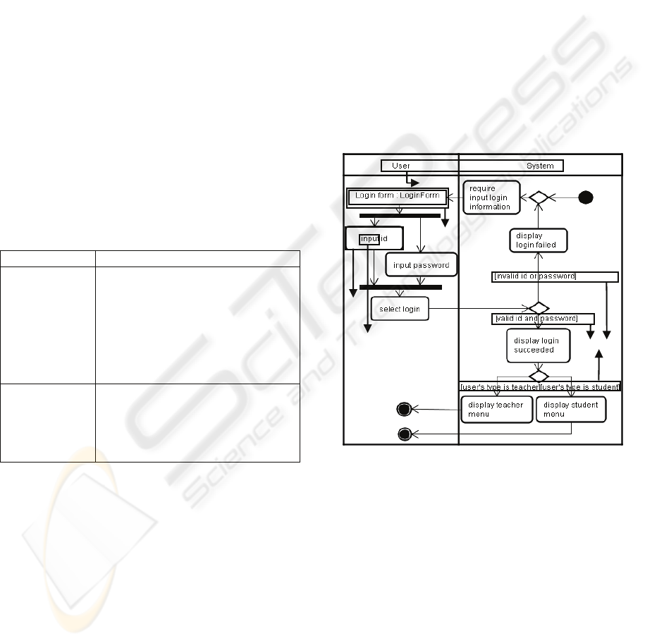
2.2 Activity Diagram
A use case is defined in the activity diagram. The
activity diagram shows the sequence of actions in
which an action represents a step of the service
provided. The interaction between the user and the
system is also defined according to the following
rules.
• To specify the boundary of the user (the actor of
the use case) and the system, the partition region in
the activity diagram is used to define each actor and
the system (see Figure 1-(1)).
• To clarify the reason for page transitions, a guard
condition should be described in the control flow
after the decision node (see Figure 1-(2)).
Figure 1: Activity Diagram for “Login” Use Case.
• To define input/output data of an action based on
the user interaction with the system, the format of
action description should be defined in the format of
“verb” + “object” in a verb phrase (see Figure 1-(3)).
The “verb” expresses an action related to an action
in HTML, and the “object” expresses the input data
for it (see Figure 1-(4)). The “verb” being used in
the activity diagram is restricted to the preselected
word related to tags in HTML, which will be
explained in Section 4.3.
• To intuitively understand the input/output data
provided to the user, the object node should be
described in an adequate position in the sequence of
actions (see Figure 1-(5)).
(1)
(2)
(4)
(5)
(3)
AUTOMATIC GENERATION OF UML-BASED WEB APPLICATION PROTOTYPES
245

The activity diagram can have several descriptions
for the same control flow process using control
nodes such as decision and merge nodes. For
example, often, a pair comprising a decision node
and a merged node is not specified in the diagram.
Therefore, for parsing activity diagrams as easily as
possible, we specify a pair of control nodes and the
number of input/output data in the control flow.
2.3 Class Diagram
In UML, a class diagram describes the structure of a
system by showing the system’s classes, attributes,
and the relationships between the classes. In our
requirements analysis model, we use a class diagram
to express a group of input/output data so that the
customers can have an idea of the data related to the
action in the service process via the prototype
system. The objects are extracted through the
process of describing object nodes in the activity
diagram. The operations and associations in the class
diagram are dealt with in the next stage based on this
class diagram.
2.4 Object Diagram
The object diagram defines the instance
specification of the class diagram so that the
concrete data may help a user to understand the
situation. In the case of defining two or more values
in a slot, we must express the values with separating
them by a comma.
3 REQUIREMENTS ANALYSIS
AND VALIDATION PROCESS
We define the requirements analysis and validation
process as follows.
1) The developer defines the use case diagram by
using the services extracted from the existing
workflows and the user’s informal requirements.
2) The developer defines the activity diagram for
every use case according to the design policy
mentioned in Section 2.2. It is important to define
the input/output data in detail so that the customer
can confirm all essential input/output data of the
required system.
3) The developer defines the class diagram for every
item of input/output data required by an action in
the activity diagram. It is important to provide
grouped data so that the customer can validate the
contents of the services.
4) The developer defines the object diagram for each
class defined in Step 3. Instance specification is
used as an example of input/output data in the
prototype system.
5) The prototype system is automatically generated
by the tool, which will be explained in Section 4.
The tool generates HTML code based on the
activity diagrams, class diagrams, and object
diagrams defined in steps 2–4.
6) The customer confirms the requirements analysis
model as meeting the requirements by using the
prototype system. He/she points out that he/she
might not be satisfied while using the prototype
system.
7) The developer modifies the model considering the
relation between the three types of diagrams
defined in steps 2–4 and the customer’s
confirmation items listed in Table 1. After
modifying the model, the tool generates the
modified prototype system. Until the customer is
satisfied, steps 5–7 are repeated.
It is not necessary for the developer to execute steps
2–4 strictly in that order.
4 DESIGN AND
IMPLEMENTATION OF THE
AUTOMATIC GENERATION
TOOL OF THE PROTOTYPE
SYSTEM
4.1 Prototype Generation Process
The tool automatically generates a prototype system
in HTML using the requirements analysis model that
comprises the three diagrams mentioned in Section
2. The prototype system consists of several pages
and their links. First, we explain how the tool
divides the model into the pages and links them with
each other by interpreting the activity diagram. Next,
we show how the tool generates the data in each
page from these three diagrams.
4.2 Generation of Pages and Links
To construct all pages and to analyze page transition,
the tool interprets the activity diagram based on the
rules mentioned in Section 2.2 in the following
manner.
To divide the activity diagram into several pages,
the tool identifies two types of trigger actions for
transition between the two partitions. While one
ICEIS 2008 - International Conference on Enterprise Information Systems
246
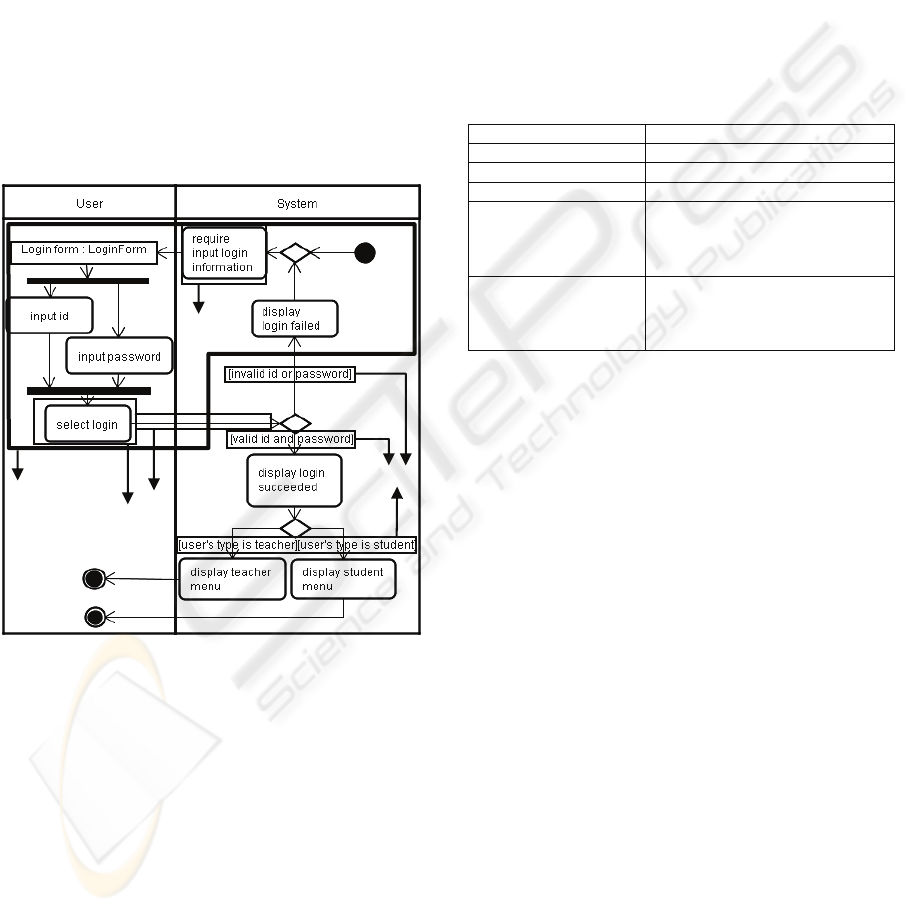
action is the last in a sequence of actions in the
system partition (see Figure 2-(1)), the other is the
last in a sequence of actions in the user partition (see
Figure 2-(2)). The former is called a system
transition trigger action and the latter, a user
interface transition trigger action. A page is defined
by the data included in the sequence of actions and
object nodes in the activity diagram wherein a user
interface transition trigger action or initial/final
node is a page delimiter (see the portion of the figure
that is marked with thick boundaries). Each path in
the sequence from a user interface transition trigger
action to a system transition trigger action defines
the transition target page (see Figure 2-(3)). The
guard condition on the control flow defines a link to
the target page, and the label of the link is defined
by the guard description (see Figure 2-(4)).
Figure 2: Interpretation of the Activity Diagram for
“Login” Use Case.
4.3 Generation of Page Data
Page data is generated by combining the object
nodes in the activity diagram, class diagram, and
object diagram. The input/output data are presented
in a table so that the customers can grasp the data
structure intuitively.
4.3.1 Interpretation of Action in the Activity
Diagram
First, the actions in the user partition of the activity
diagram are interpreted as follows. The input/output
data in a page is analyzed by the actions and object
nodes that are included in the frame. For example,
the frame in Figure 2 includes one object node
“Login form” and two actions “input id” and “input
password.” The tool analyzes a label of the action
and extracts a “verb” and the “object.” The
preselected “verbs” are given correspondence to the
appropriate input forms in HTML, as shown in
Table 2. In this example, “input” expresses a tag of
text input form. On the other hand, the verbs
“display” and “require” in a sequence of actions in
the system partition are interpreted as a type of
emphasis tag such as <H2> , <U>, and <B>.
Table 2: Action Verb and Type of Input Form.
Verb Types of input form
“input” Text input form
“single-select” Radio select form
“multiple-select” Check box select form
“select” (This specifies
a user interface
transition trigger
action.)
Link
“confirm” If there is an instance specification
related to the object, the slot is
displayed on the page; if not, the
object itself is displayed.
4.3.2 Generation of a Table of Data
For each object node, a table is generated by
combining three kinds of data such as the object
node of the activity diagram, the class of the class
diagram, and the instance specifications of the object
diagram. Figure 3 shows that the elements of a table
are decided according to the definitions of these
three kinds of data.
The table that represents a set of input/output
data is generated as follows.
1. The table name is generated from the object name
of an object node. The object name of the object
node "Task list :Task" in Figure 3 decides the table
name “Task list”.
2. If a class is specified for the object node, the
attribute column names are generated from the
attributes of the class. Three attribute column names
such as “category”, “task” and “detailInformation”
are decided by the attribute name of the class
"Task."
3. If a class is specified for the object node and the
class is specified for the instance specifications, the
instance rows are generated from the slots of the
instance specifications.
(2
(3
(
4
(1
The
boundary of
a page.
AUTOMATIC GENERATION OF UML-BASED WEB APPLICATION PROTOTYPES
247
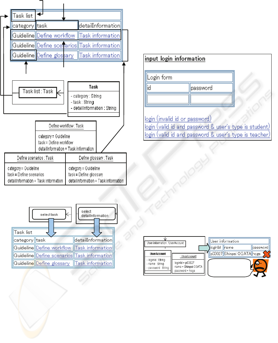
Figure 3: Generation of a Table of the Object Node.
Figure 4: Correspondence of Action and Attribute Values.
Attribute values can be interpreted in two ways. One
interpretation pertains to the fact that the attribute
value holds an input form that is specified with the
“verb” in the action label; when the “object”
corresponds to the target attribute name. When the
type of the input form can be selected and has an
instance specification, the attribute value is defined
by a link that has a corresponding label for the slot
(see Figure 4). The other is that the attribute value
holds the entire slot of the instance specification to
provide a set of concrete values to the customer as
an example. The number of instance rows equals the
number of instance specifications.
4.3.3 Example of a Generated Page
Figure 5 illustrates an example of a part of the
generated page from the activity diagram shown in
Figure 2, and provides the definition of the
“LoginForm” class. Apart from this main page, three
other kinds of pages linked to the three labels of
branch conditions are created.
Figure 5: The Prototype System for “login” Use Case.
4.4 Restriction on Input/Output Data
Input/output data on a page are generated by using
all the elements defined in the three kinds of
diagrams. Although the developer needs all of these
elements to implement the target system, it is
sometimes desirable for the customers to restrict
input/output data to a page.
Figure 6: Restriction on Attribute Values.
For example, the login service must not display the
user password, as shown in Figure 6.
Moreover, it is sometimes more effective to display
a set of adequately restricted values for the
customer’s understanding, as shown in Figure 7.
Model Prototype system
We must hide
a password!!
Attribute
value
Instance row
Table name
Attribute column
name
ICEIS 2008 - International Conference on Enterprise Information Systems
248
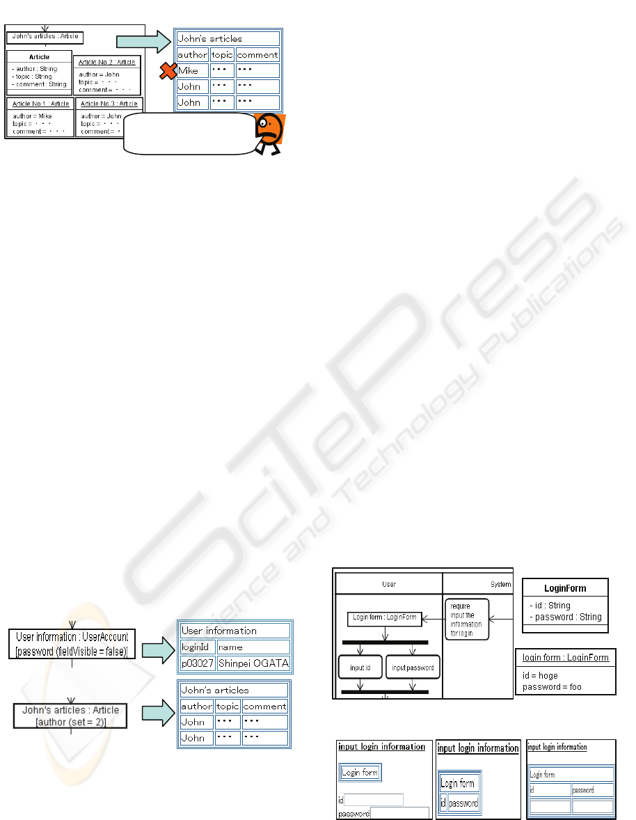
Figure 7: Restriction on the Number of Instance
Specifications.
To express such a restriction on input/output data,
we add the notations to the state of an object node in
the activity diagram. As a result, we can change the
state of an object according to the position of its
appearance in the activity diagram and the contents
of the action. The following are the notations for the
state description of an object node in the activity
diagram.
• Depending on whether or not a specific
attribute column should be hidden, we write
fieldVisible = true or fieldVisible = false.
• Depending on whether or not all the attribute
values of a specific column should be hidden,
we write valueVisible = true or valueVisible =
false.
• When the number of instance specifications
obtained should be limited, we write set = the
number.
• When a new row should be created, we write
new or nothing.
If we add the notations to the state of the object node
in the activity diagram, as shown in Figure 8, the
generated prototype system shown in Figures 6 and
7 changes to the one shown in Figure 8.
Figure 8: Description of the State of the Object Node.
4.5 Implementation
The tool was implemented by using Java. The
requirements analysis model is defined by using
JUDE professional (Model Version 25)
(ChangeVision, 2007), a UML modeling tool. The
main steps of the process are as follows.
1) The tool reads a JUDE file that defines the
requirements analysis model and the information
of the partition names.
2) It parses the requirements model and maps it to
the internal object model of the tool.
3) It checks that the activity diagrams conform to the
rules mentioned in Section 2.2.
4) It generates a prototype system by following the
steps mentioned in this section.
4.6 Stepwise Development of the
Requirements Analysis Model
The tool generates a prototype system from the
information combined from the three diagrams,
namely, activity diagrams, class diagrams, and
object diagrams. However, in the stage where the
developer has defined the activity diagrams, he/she
can confirm the validity by generating the prototype
system. After the confirmation, he/she can define a
richer prototype by adding the class diagram and the
object diagram. Such a characteristic of the tool
makes it possible to refine the requirements analysis
model as per the customer’s new requirements in the
validation process. Three diagrams shown in Figure
9 depict the generation of the prototypes (see Figure
10) for each stage.
Figure 9: Three Diagrams for “Login” Use Case.
Figure 10: Three Types of Generated Prototypes.
(b)Activity and class
(c)All
(a)Activity
Model
Prototype system
We want to get only
John’s articles!!
AUTOMATIC GENERATION OF UML-BASED WEB APPLICATION PROTOTYPES
249
5 EXPERIMENTAL RESULTS
AND DISCUSSION
5.1 Evaluation of Experimental
Development
To evaluate the effectiveness of the prototyping
method, we have developed a file repository
management service, which is the same as that used
with the current system for supporting related to the
software development group in our department. We
have assumed that the workflow process and the
input/output data of the current system constitute the
user requirements. The aim of the experiment is to
confirm that the prototype system generated by our
method is equivalent to the current system.
Moreover, we confirm that the prototype system can
be refined as easily as possible.
Table 3: Results of the Experiment.
Items
Confirmation Refinement
1)
○ ○
2)
○ ○
3)
○ ○
Business Work
Flow Process
4)
○ ○
5)
△ △
6)
○ △
Input/Output Data
7)
○ △
○:Enough ,△ :Partially enough ,×:
Impossible
Table 3 shows the evaluation result of the method
from the perspective mentioned in Table 1 during
the experimental development. Since the interaction
between the two kinds of partitions—user and
system—have been clarified, the business workflow
process can be correctly defined by the activity
diagram based on the rules mentioned in Section 2.2.
Another reason is that we can adjust the transition of
the pages not only by the guard conditions in the
system action sequence but also by the rich
expression of the control flow in an activity diagram.
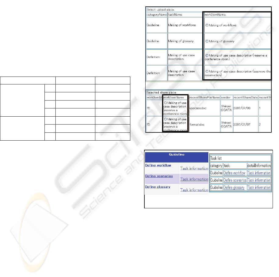
However, it becomes clear to us that there are some
problems in input/output data representation.
In item 5, the overlapping attribute name in
different classes restricts us from using different
input forms for different attribute names in the same
page. Figure 11 presents an example of this problem.
This is the reason that the “object” of the action in
an object node is not related to the attribute for each
class. In this case, attribute “workItemName” is
defined in both the classes i.e., “SearchUploadFile”
and “SharedPlace.” As the “verb” of the action in
the object node is “select,” their input form becomes
the same radio select form.
In item 6, a table representation makes it possible to
grasp a set of data intuitively. However, we cannot
specify such a table layout, as shown in Figure 12.
In item 7, we can define various instance
specifications; however, we cannot specify the order
of obtaining them for the purpose of the UML
modeling tool.
Figure 11: Part of the File Upload User Interface.
Figure 12: Problem of Table Layout.
5.2 Discussion
Almost every system should provide appropriate
services for each user, based on an authority policy.
However, at present, the prototype system
encompasses all situations for all uses at once. To
clearly understand the scope of what the user can do
in the system, irrelevant information should not to be
provided. To solve this problem, the prototype
system needs to provide all situations for a specific
user and for specific test cases. A test case implies a
(b) Prototype system
(a) Existing system
ICEIS 2008 - International Conference on Enterprise Information Systems
250

concrete scenario of the specified user for each page
transition. For example, there are three labels of
branch conditions in Figure 5. If the type of the user
is a student, then the last label should not be
displayed.
5.3 Related Work
A number of methods have been proposed for UML-
based prototyping of user interfaces (Díaz et al.,
2001; Elkoutbi et al., 2006; Cruz and Faria, 2007).
These researches adopted several UML diagrams
such as sequence diagrams and collaboration
diagrams. Diaz et al. (Díaz et al., 2001) proposed a
method for the automatic generation of user
interface using class diagrams and MSCs (Message
Sequence Charts), which are extended sequence
diagrams in UML, along with the stereotypes. The
user interface thus generated can be edited by a
target visual programming tool. However, it is not
clear whether new customer requirements can be
correctly reflected in the requirement analysis model
being used in the subsequent development phase.
We propose a method for validating the requirement
analysis model through an iterative validation
process. Elekoutb and Cruz propose more
formalized methods using OCL for the specification
verification. However, it is not clear whether the
resultant user interface can represent concrete
example data for the specified scenario. Object
diagrams related to the class diagrams not only
express the specified scenario but also enrich the
prototype stepwise for both the customers and the
developer.
6 CONCLUSIONS
This paper proposed a method for incremental
validation of Web applications; this method
automatically generates a prototype system from the
UML-based requirements analysis model. The
automatic generation tool enables the developer to
define the analysis model that reflects the customer’s
validation results. Moreover, the developer can carry
out incremental and efficient development of the
model by repeating the prototype generation.
Future tasks involve improving our method in
order to enable the developer to model the
association between several services and the
relations between the users and services. We plan to
improve the automatic generation tool so that it can
interpret another activity diagram that specifies the
order of processing all the use cases of the system
for each authority. Moreover, the tool is expected to
be able to generate a prototype for each actor by
interpreting the relations between the actors and use
cases.
REFERENCES
Onishi, A., and Go, K., 2002. Requirements Engineering,
Kyoritsu publishing company (in Japanese). Tokyo.
Díaz, J. S., López, O.P., and Fons, J.J., 2001. From User
Requirements to User Interfaces: A Methodological
Approach. In CAiSE’01, 13th Conference on
Advanced Information Systems Engineering. LNCS
2068,pp. 60-75.
Davis, A.M., 1993. Software Requirements: Objects,
Functions and States, Prentice Hall, Englewood Cliffs.
Kotonya, G., and Sommerville, J., 2000. Requirements
Engineering: Processes and Techniques, John Wiley
& Sons.Hoboken.
Object Management Group, 2007. Unified Modeling
language, www.uml.org.
Fowler, M., 2004. UML Distilled Third Edition: A Brief
Guide to the Standard Object Modeling Language,
Pearson Education.
ChangeVision, 2007. JUDE, www.change-vision.com.
Elkoutbi, M., Khriss, I., and Keller, R. K., 2006,
Automated Prototyping of User Interfaces Based on
UML Scenarios. Journal of Automated Software
Engineering, vol.13, no.1, pp.5-40.
Cruz, A. M. R., and Faria J. P., 2007. Automatic
Generation of User Interfaces from Domain and Use
Case Models. In QUATIC’07, 6th International
Conference on the Quality of Information and
Communications Technology. pp.208-212.
AUTOMATIC GENERATION OF UML-BASED WEB APPLICATION PROTOTYPES
251
