
MODELING AND SIMULATION OF A NEW PARALLEL ROBOT
USED IN MINIMALLY INVASIVE SURGERY
Doina Pisla, Calin Vaida, Nicolae Plitea
Technical University of Cluj-Napoca, Department of Mechanics and Computer Programming
Constantin Daicoviciu 15, RO-400020 Cluj-Napoca, Romania
Jürgen Hesselbach, Annika Raatz, Marc Simnofske, Arne Burisch
Technical University of Braunschweig, Institute of Machine Tools and Production Technology
19B Langer Kamp, D-38106 Braunschweig, Germany
Liviu Vlad
University of Medicine and Pharmacy “Iuliu Hatieganu”, Surgery Clinic III
Emil Isac 13, 400023 Cluj-Napoca, Romania
Keywords: Parallel robots, Minimally invasive surgery, Modeling, Simulation, Kinematics, Workspace.
Abstract: Surgery is one of the fields where robots have been introduced due to their positioning accuracy which
exceed the human capabilities. Parallel robots offer higher stiffness and smaller mobile mass than serial
ones, thus allowing faster and more precise manipulations that fit medical applications. In the paper is
presented the modeling and simulation of a new parallel robot, based on an innovative structure, used in
minimally invasive surgery. The parallel architecture has been chosen for its superiority in precision,
repeatability, stiffness, higher speeds and occupied volume. The robot kinematics, singular position
identification and workspace generation are illustrated. Using the developed virtual model of the parallel
robot, some simulation tests are presented.
1 INTRODUCTION
Simulation is one of the essential aspects in the
robots research field. The industrial trend is to
develop simulation systems, which could be helpful
for the robot off-line control and for the robot
operational workspace generation. Due to the high
graphical possibilities and memory capacities, the
personal computers offer already the necessary
instruments to achieve efficient simulation systems.
Within the simulation system, an important role
plays the achievement of a virtual robot functional
model, which allows its interactive visualization and
functional simulation.
The first important application of the simulation
systems is during the design process of a new robot
structure or a new flexible cell. In both cases it is
possible to test the functionality and the restrictions
influence without the actual building of the
prototype. In this way the costs, the implementation
and testing time are considerable reduced.
The second kind of important application of the
simulation systems refers to the existent robots that
could be better programmed, analyzed and
optimized if the research activity is considered.
Within the simulation systems, the visualization
of the robot trajectory with collision detection is
achieved, offering a safer system especially for the
case in which several robots are coupled, situation
that requires a more rigorous planning.
The robotized system performance can be tested
without any danger for the man or for the robot. The
programs generated within the simulation system
could be optimized before their practical
implementation leading to any damage avoidance
due to programming facilities, cost reduction and
quality improvement.
194
Pisla D., Vaida C., Plitea N., Hesselbach J., Raatz A., Simnofske M., Burisch A. and Vlad L. (2008).
MODELING AND SIMULATION OF A NEW PARALLEL ROBOT USED IN MINIMALLY INVASIVE SURGERY.
In Proceedings of the Fifth International Conference on Informatics in Control, Automation and Robotics - RA, pages 194-201
DOI: 10.5220/0001500201940201
Copyright
c
SciTePress

Another advantage of the simulation systems
consist in their use in the research field. New control
algorithms can be created and tested before
investments in the necessary hardware devices for
the robot control to be made.
To the parallel robots simulation systems are
attributed different meanings: numerical simulation
for a specific robot function or element in transition;
parallel computing for the robot state and transitions
definition; the graphical simulation of the robot
structure and motion. In some cases the animation is
considered as simulation.
Geometric modeling is one of the keystones of
CAD systems. It uses mathematical descriptions of
geometric elements to facilitate the representation
and manipulation of graphical images on a computer
display screen. In three-dimensional representations,
there are four types of modeling approaches, (Foley
et al., 1990) and (Pisla, 2001): Wire frame
modelling; Surface modeling; Solid modeling;
Hybrid solid modeling.
Simplifying the virtual model enables
researchers to apply for the use of different methods
(usually starting with the most recommended one) in
correspondence with the available time and existing
endowment in order to compare the obtained results
and refine only the most adequate solution. In
practice, the application of simulation techniques is
used in two situations: for already made structures to
improve their characteristics; for new designed
structures to forecast their behaviour before
construction.
Lately is considered more the second case, due to
the intense development in creating new structures
with better dynamics and larger cinematic facilities,
or considering the parallel kinematic, a multibody
system can be designed to be used like a machine
tool or like a robot, therefore the same kinematical
structure must respond to different tasks that can be
demonstrated with the simulation techniques.
One of the first achieved models in order to
achieve the robot simulation is the geometric model.
There are many possibilities to create this model
also in this case. In respect with the chosen model,
different aspects regarding the mechanism properties
or actuating methods are emphasized.
The modeling process is oriented to the
correlation between the method and the structure in
order to point out the influence of the modeling
instruments on the structure design.
Considering that the robot performances depend
on the adequate combination between the designed
structure, the actuating and the control system, the
applying of suitable modeling and simulation
techniques could improve the robot design and
control through: identification of standardized
element behaviour with modular dimensions;
identification and visualization of the operational
workspace, which is harder to be achieved in the
parallel robot case; identification of different parallel
robot singularities and their avoiding; trajectory
visualization which must be programmed for certain
parallel robot tasks; speeds and acceleration
visualization in different trajectory points.
Regarding the application of robots for medical
applications there are some investigators focused on
exploring the capabilities of parallel robots in this
field (Ben-Porat, 2000), (Glozman, 2001), (Grace,
1993). AESOP robotic arm, used to guide a tiny
camera inside the body, was the first robotic system
used in surgery dating from 1993 (Brown
University, 2005). It was produced by Computer
Motion, which developed several such versions of
AESOP until they created Zeus
TM
Robotic Surgical
System with three robotic arms attached on the side
of the operating table. A competitor of Computer
Motion, Intuitive Surgical, designed another
revolutionary equipment, da Vinci
TM
Surgical
System, which became the market competitor of
Zeus until 2003 when the two companies merged
(Brown University, 2005).
Most of the robots, which assist the surgeons, are
serial robots (Brown University, 2005). The serial
module generates a large workspace while the
parallel module is steadier and offers a high
accuracy during the surgical operation. In this case,
there are used force control algorithms in order to
ensure the safety behavior and the accepted
accuracy.
Parallel robots offer a higher stiffness and
smaller mobile mass than serial robots, thus they
allow faster and more precise manipulations. The
problems concerning parallel structures kinematics
are usually more complicated than for the serial
structures. The drawbacks of serial robots,
determined by their structural construction, motivate
the research in the field of robotic assisted surgery
for a continuous search of task oriented robot
architectures that best fit a specific group of medical
applications.
The paper is organized as follows: Section 2 is
dedicated to modeling techniques; Section 3 deals
with kinematic modeling of the new parallel
structure designated to minimally invasive surgery;
Section 4 presents its workspace modeling, Section
5 presents the developed simulation program for
parallel robots with some simulation tests on a
studied parallel robot. The conclusions of this work
are presented in Section 6.
MODELING AND SIMULATION OF A NEW PARALLEL ROBOT USED IN MINIMALLY INVASIVE SURGERY
195
2 MODELING TECHNIQUES
Bottom-up Modeling Assembly Approach is the
modeling technique where component parts are
designed and edited in isolation of their usage within
some higher level assembly (Pisla, 2004). All
assemblies using the component are automatically
updated when opened to reflect the geometric edits
made at the piece part level. Using the bottom-up
approach, characteristic of traditional engineering
design practices, designs are built from known
components (embodiments) in anticipation of
satisfying functional requirements. The bottom-up
approach is known to be highly iterative. In the case
of large or complex designs, the problem quickly
leads to combinatorial explosion, inefficiency in the
design process, and difficulties assessing the
effectiveness and merits of design alternatives.
Bottom-up design is the traditional method. In
bottom-up design, you create parts, insert them into
an assembly, and mate them as required by your
design. Bottom-up design is the preferred technique
when you are using previously constructed, off-the-
shelf parts. An advantage of bottom-up design is that
because components are designed independently,
their relationships and regeneration behavior are
simpler than in top-down design. Working bottom-
up allows you to focus on the individual parts.
Top-Down Modeling Assembly approach is the
modeling technique where component parts can be
created and edited while working at the assembly
level (Pisla, 2004). Geometric changes made at the
assembly level are automatically reflected in the
individual component part immediately. In the top-
down approach, characteristic of a systems
engineering process, design is driven from
functional requirements toward solution alternatives.
While design solutions using this approach are likely
to meet functional requirements, there is no
guarantee that solutions are realizable in terms of
physical manifestations.
Top-down design is different because you start
your work in the assembly. You can use the
geometry of one part to help define other parts, or to
create machined features that are added only after
the parts are assembled. You can start with a layout
sketch, define fixed part locations, planes, and so on,
then design the parts referencing these definitions.
For example, you can insert a part in an assembly,
then build a fixture based on this part. Working top-
down allows you to reference model geometry, so
you can control the dimensions of the fixture by
creating geometric relations to the original part. That
way, if you change a dimension of the part, the
fixture is updated.
Analyzing both techniques characteristics, the
bottom-up assembly approach has been chosen for
parallel robot modeling due to their advantages.
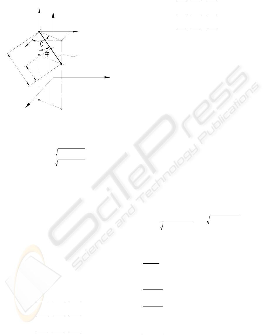
3 KINEMATIC MODELING OF
THE PARAMIS ROBOT
In Figure 1 is presented the kinematic scheme of the
new parallel structure – PARAMIS, which can be
used for surgical instruments positioning (Plitea,
2007). The structure has three degrees of freedom in
space and it consists of three active joints (two of
them are prismatic and one is rotational). The
passive joints are two cylindrical joints, one
prismatic joint and one Cardan joint. The robot must
position the end of the laparoscope, namely the
video camera in any point of the operational field.
prismatic
joint
Cardan
joint
cylindrical
joint
cylindrical
joint
rotational
joint
prismatic joints
EEE
E(X , Y , Z )
BBB
B(X , Y , Z )
AAA
A(X , Y , Z )
d
h
e
f=2
f=4
b
r
A
2
q
q
1
3
q
X
Y
Z
Figure 1: Kinematic scheme of the new parallel robot.
The particularity of this motion is the fact that
the endoscope will move around a fixed point in
space, which is the entrance point of the trocar in the
abdominal wall of the patient (namely the point B).
The presence of the passive Cardan joint before the
laparoscope will allow the motion around the fixed
point of the abdominal wall. The trocar, the
abdominal entrance point and the endoscope can be
seen as a virtual joint with four degrees of freedom,
which allow the camera the rotation around the three
axis and a translation parallel with the axis of the
trocar. Thus, the endoscope can be positioned in any
point of the abdominal area using the three degrees
of freedom of the robot. The geometrical parameters
of the PARAMIS robot are given by
BBB
Z,Y,X;h,d,b (figure 1). In (Plitea, 2007)
the inverse and direct geometric and kinematic
ICINCO 2008 - International Conference on Informatics in Control, Automation and Robotics
196
models for speeds and accelerations of the structure
have been already presented.
Z
1
h
h
laparoscope
X
Y
E
y'
E
x'
z'
E
AAA
A(X , Y , Z )
BBB
B(X , Y , Z )
EEE
E(X , Y , Z )
Figure 2: The angles of the passive Cardan joint: φ, θ.
The implicit functions equation system, which
has been obtained from the kinematic model, are:
() ()
() ()
()
⎪
⎪
⎪
⎩
⎪
⎪
⎪
⎨
⎧
=−≡
=⋅
⎥
⎦
⎤
⎢
⎣
⎡
−−+−≡
=⋅
⎥
⎦
⎤
⎢
⎣
⎡
−−+−≡
0qZq,Zf
0qsinqqdbYq,q,q,Yf
0qcosqqdbXq,q,q,Xf
1A1E3
3
2
12
2
A321E2
3
2
12
2
A321E1
(1)
With the notations:
[][]
T
321
T
EEE
q,q,qq,Z,Y,XX ==
&
&
(2)
Through derivation of the relations (1), it yields:
0qBXA =⋅+⋅
&
&
(3)
where A is the Jacobian matrix of the direct
kinematics and B is the Jacobian matrix of the
inverse kinematics, x the vector of end-effecter
coordinates and q the vector of generalized
coordinates of the actuators.
The form of the A and B matrices are:
⎥
⎥
⎥
⎥
⎥
⎥
⎥
⎦
⎤
⎢
⎢
⎢
⎢
⎢
⎢
⎢
⎣
⎡
∂
∂
∂
∂
∂
∂
∂
∂
∂
∂
∂
∂
∂
∂
∂
∂
∂
∂
=
E
3
E
3
E
3
E
2
E
2
E
2
E
1
E
1
E
1
Z
f
Y
f
X
f
Z
f
Y
f
X
f
Z
f
Y
f
X
f
A
(4)
⎥
⎥
⎥
⎥
⎥
⎥
⎥
⎦
⎤
⎢
⎢
⎢
⎢
⎢
⎢
⎢
⎣
⎡
∂
∂
∂
∂
∂
∂
∂
∂
∂
∂
∂
∂
∂
∂
∂
∂
∂
∂
=
3
3
2
3
1
3
3
2
2
2
1
2
3
1
2
1
1
1
q
f
q
f
q
f
q
f
q
f
q
f
q
f
q
f
q
f
B
(5)
3.1 Singularities Analysis
An important problem for the parallel robots is to
identify and avoid singularities, ensuring the system
stability and kinematic accuracy. Physically, these
singular positions lead to an instantaneous change in
the system number of degree of freedom and hence
loss of controllability and degradation of the natural
stiffness. Therefore it is important to identify
singular configurations at the design stage in order
to improve the system performance. For an optimal
robot control these positions should be identified and
avoided from the robot workspace.
A number of papers have studied the singularity
problem for close kinematic chains (Merlet, 2005),
(Sefrioui, 1992), (Park, 1999), (Romdahne, 2002).
The used algorithm for the PARAMIS structure
singularity analysis is based on the deriving the
determinants for the two Jacobian matrices derived
from the inverse and the direct geometric model.
Singularities of Type I. First type of singularities
occurs when the determinant of the Jacobian matrix
B is zero.
Using (1), it yields:
()
()
⎥
⎦
⎤
⎢
⎣
⎡
−−+⋅
−−
−
=
2
12
2
2
12
2
12
qqdb
qqd
qq
)Bdet(
(6)
If det(B)=0, physically, the parallel robot looses
one or more degrees of freedom.
Case 1
.
21
qq
=
- The mechanisms is locked.
The situation corresponds to the positioning on the
horizontal plane of the rod of length d (the first
extreme position).
Solution
. Constructively, the mechanical
structure of the robot will impose
21
qq <
Case 2
.
(
)
12
2
12
2
qqdqqd −=≡−=
- The
mechanisms is locked.
This situation corresponds to
the positioning on the vertical axis of the rod of
length d (the second extreme position).
Solution. Constructively, the structure of the
robot will not allow displacements so long as the rod
of length d to reach a vertical position.
MODELING AND SIMULATION OF A NEW PARALLEL ROBOT USED IN MINIMALLY INVASIVE SURGERY
197
Case 3.
() ()
0qqd0b0qqdb
2
12
2
2
12
2
>−−>=−−+
is impossible (as they represent lengths of
mechanical components).
Singularities of Type II. Second type of
singularities appears when the determinant of the
Jacobian matrix A is zero.
Using (1), it yields:
()
2
1
h
h
1Adet
⎟
⎟
⎠
⎞
⎜
⎜
⎝
⎛
−=
If det(A)=0, the system gains one or more
degrees of freedom.
Case 1
.
1
hh = it yields a point where the robot
cannot be controlled. In case of the point A will
superpose over point B.
Solution.
The attachment mechanism of surgical
instruments on the robot and the shape of the trocar
will not allow point A to superpose over point B. (In
this situation the instrument or laparoscope will be
situated entirely in the patient).
Case 2
. 0h
1
= , correponds to the situation when
the laparoscope is positioned completely out of the
surgical field, with
BE ≡ situation which will be
impossible to attain with the robot, as the insertion
and removel of the laparoscope is done manually by
the surgeon.
The Third Type of Singularities so called
“architectural singularities” takes place when both
Jacobian determinants are zero.
Superposing the cases when the two
determinants are equal with zero, it can be easily
seen that in none of the above situations the
determinants cannot be null in the same time. In
conclusion, from the constructive point of view, for
the functioning conditions imposed, there are no
singularity points of type III.
These types of singularities can be easily
avoided in the design stage.
Based on the fact that the only singularity cases
appear in areas where the positions that the robot
cannot attain it can be concluded that, in the working
space of the robot, there are no points where the
robot cannot be controlled.
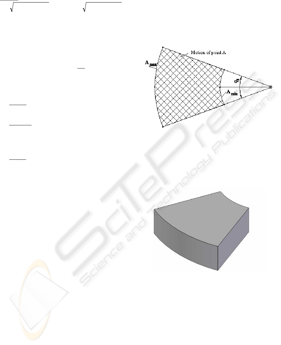
4 WORKSPACE MODELING
For the geometrical determination of the working
space of point E (the laparoscope extremity where
the camera is placed) the first step is the
determination of the working space of point A and
its projection, keeping in mind that for on the
segment ABE the point B is fixed in space and AE
has a constant length.
The working space of point A can be easily
determined, by determining the cross-sections within
the working space in a parallel plane with OXY
which for the limits imposed for
1
q and
2
q will
have the same shape for any position of the Z axis.
Figure 3: Motion of point A in a parallel plane with OXY
(horizontal).
The hatched area in Figure 3, represents all the
possible coordinates that point A can attain in a
horizontal plane. Generating the three-dimensional
working space it results the shape presented in
Figure 4.
Figure 4: The workspace of point A.
For the workspace generation for point E has to
be considered that the laparoscope (or any other
surgical instrument) has a constant length and will
always pass through a fixed point in space. The
working space of point E by generating two
intermediate working spaces whose intersection will
represent the effective working space. The first
intermediate working space is generated by
projecting the point A from sections parallel with
OXY plane. The second one is generated from
sections of the working space of point A
perpendicular on the plane OXY.
ICINCO 2008 - International Conference on Informatics in Control, Automation and Robotics
198
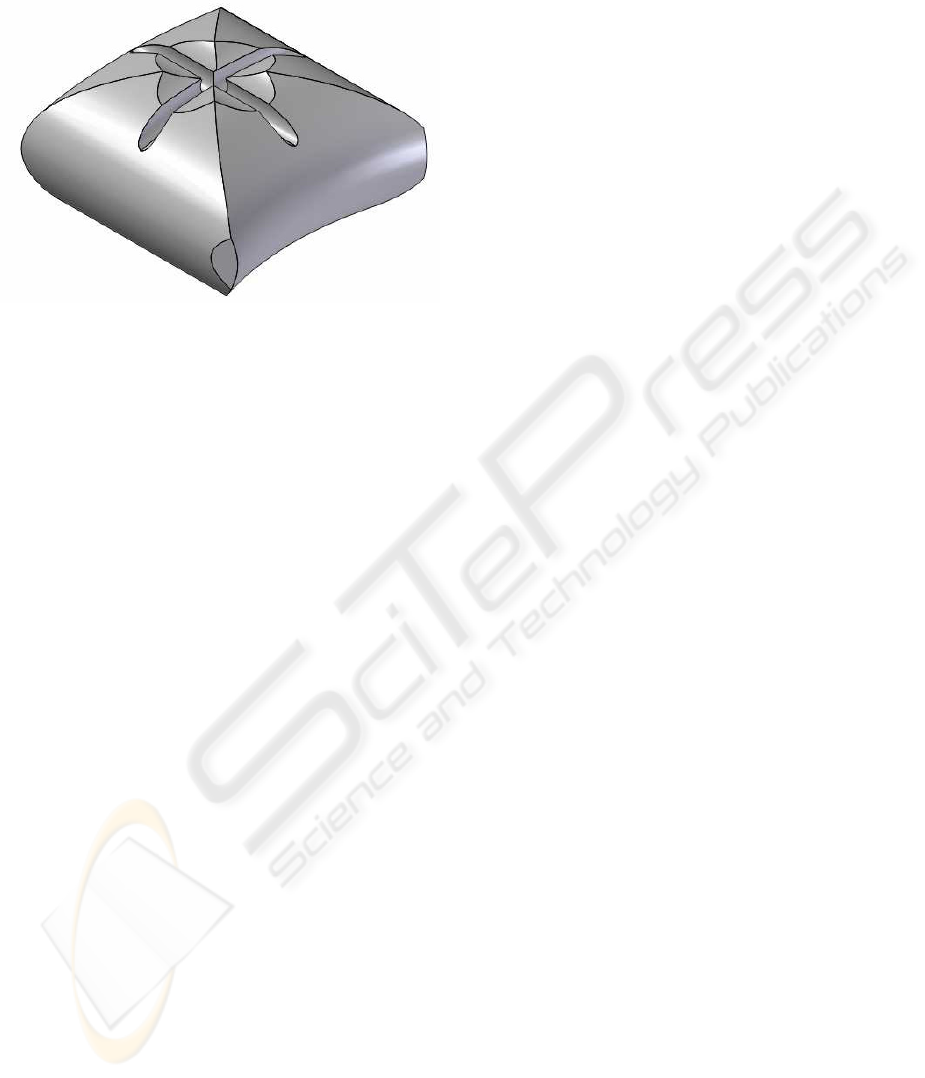
The intersection of the two intermediary
volumes will result in the working space of point E
presented in Figure 5.
Figure 5: The workspace of point E.
5 SIMULATION PROGRAM FOR
PARAMIS PARALLEL ROBOT
A complex simulation program was developed in
order to study the geometric, kinematic and dynamic
characteristics of parallel robots with different
degrees of freedom (Pisla, 2001), (Pisla, 2005).
This simulation system consists of the following
modules:
-the geometrical module (GM) defines the robot
geometric structure;
-the kinematic module (KM) defines the parallel
kinematic structure. The KM consists of: the
algorithms for the kinematics, the algorithms for
workspace generation and for singularities
identification;
-the modeler (MM) represents the combination
of the geometrical representations, kinematic
descriptions and the adequate disposition of different
objects;
-the simulator (SM) has the main task to
compute the current state of the parallel robot with
respect to certain instructions such as: the robot
source program or signals which are generated by
sensors;
-the graphical module (GPM) is responsible with
the simulated robot transformations and screen
graphical visualization.
The simulator is interactively achieved such as
the user could influence the simulation parameters
and could be informed about the possible errors
during the simulation process.
The simulator determinates the next robot state,
independent of the input mode. If an error appears,
the user is informed through an error message with
its type and elimination way. The simulator is
interactively achieved such as the user could
influence the simulation parameters and could be
informed about the possible errors during the
simulation process.
The data exchange between simulation system
modules is achieved through data files, which allow
future module integration in the existing system and
makes easy the data exchange with another off-line
programming systems.
For the graphical modeling of the parallel
structures it was used Solid Edge
©
, one of the most
advanced software for computer aided design,
available on the market (www.solidedge.com). This
program was selected especially for its outstanding
performances in terms of stability and user-friendly
interface, and even more for its total compatibility
with Visual Basic.Within the simulation system the
virtual graphical model of parallel structures has
been created.
The geometric parameters of the parallel
structure can be modified within the 3D modeling
software (Solid Edge Assembly) influencing the
simulation environment. The assembly relations
between parts, between subassemblies or between
parts and subassemblies can be also modified (Pisla,
2001), (Pisla, 2004).
The program has the possibility to select the
parallel structure from a list in accordance with the
class of the mechanism and its degree of freedom.
The parallel structure parameterization enables
the possibility to develop a study regarding the
geometric optimization and the robot workspace
shape.
The results obtained are useful for the designers
not only to understand the distribution of
characteristics of the workspaces for various
geometrical parameters of parallel structures, but
also to optimize the parallel robots.
The presented simulation system enables the
motion visualization, it is valid for any structure of
parallel robot enabling to introduce the kinematic
model over the virtual robot the single foreseen limit
being the hardware computing capacity. The
introduction of extra conditions related to any
element, joint or overall behaviour of the robot is
possible with a small number of actions.
These facilities of the simulation software enable
the possibility to develop a complex study about the
kinematics and dynamics in order to optimize the
parallel structure.
MODELING AND SIMULATION OF A NEW PARALLEL ROBOT USED IN MINIMALLY INVASIVE SURGERY
199
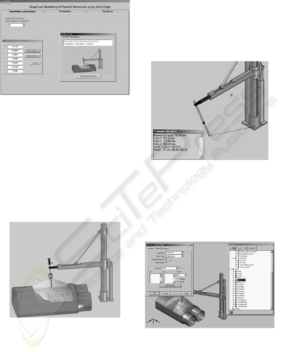
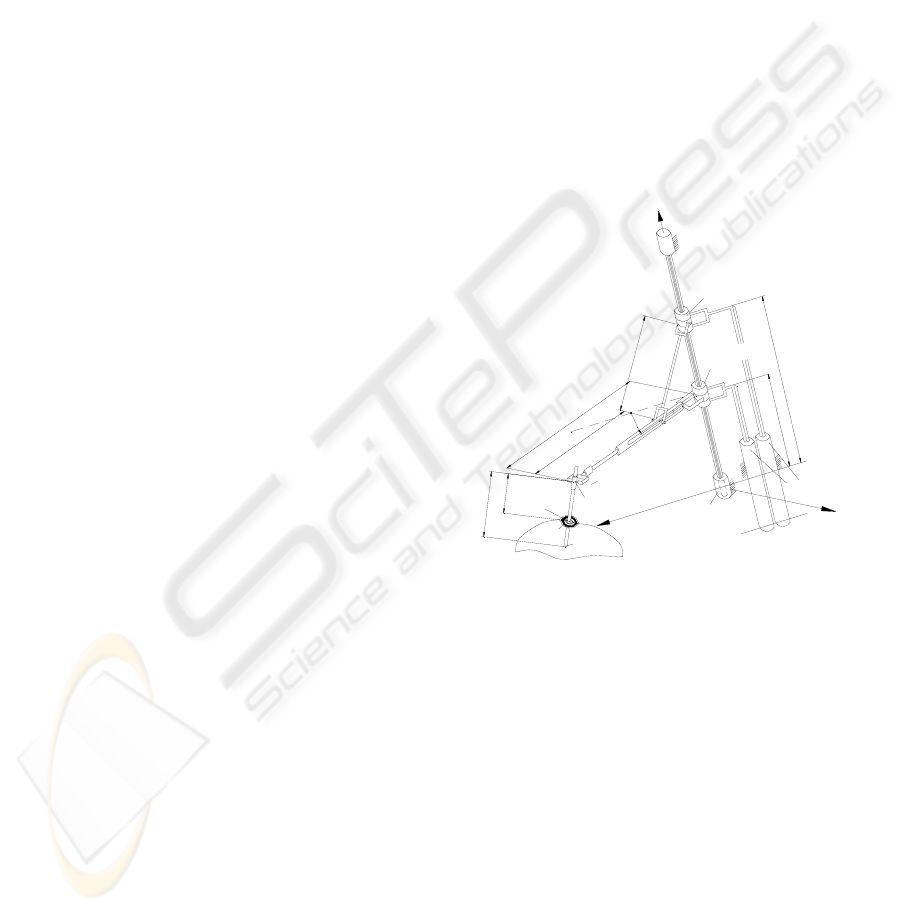
Figure 6: Simulation of the PARAMIS parallel structure.
In Figure 6 is presented the graphical interface for
graphical modeling for different parallel structures.
The kinematic algorithms have been implemented in
the kinematical module (Kinematics). In the
simulation is included the parallel robot with the
instrument and the virtual human body.
Within the simulation system (Figure 6) the
virtual graphical model was created. The 3D
functional model of the parallel structure allows the
designer to understand better its form and its
functionality. Using the Solid Edge Assembly
module it is possible to impose the assembling
conditions between the components including the
mounting possibilities and the tolerance for and
between the parts.
Figure 7: The PARAMIS robotic system.
The simulations were performed using the
parallel robot presented in figure 7 which
manipulates the laparoscope in the virtual human
model to ensure also the fixed point in the working
space of the robot (point B from Figure 1).
The virtual model was used for the validation of
the geometrical model. For that, the robot was
placed in an arbitrary position and all its parameters
measured, including the point B (Figure 1). The
second step was the computation of the coordinates
of the point E in parallel with their measurement on
the virtual model (Figure 8).
The calculated results based on the equations
matched 100% with the ones given by the virtual
model.
Figure 8: Validation of the geometric model.
The second goal concerning the virtual model
was its use for the simulation of the robotic structure
in the medical environment created. In this stage it
was important to achieve proper motions for
different commands in the active joints. Solid Edge
allows a the definition of motion trajectories in
terms of displacements, speeds and accelerations as
points, lines or equations implemented in the active
joints, as shown in figure 9.
Figure 9: Input of motion trajectory in a module.
The simulation enabled the validation of the
structure from the points of view of both engineers
and surgeons and opened the way for the next step in
the PARAMIS robotic design evolution, the
construction of an experimental model.
ICINCO 2008 - International Conference on Informatics in Control, Automation and Robotics
200

6 CONCLUSIONS
Modeling and simulation are important and essential
stages in the engineering design and problem solving
process because it allows to prevent the risks and to
lower the costs that appear with the design,
construction and testing stage of a new robot. Since
parallel mechanisms have a complex structure, using
the proposed approached of modeling and
simulation will lead to an increased efficiency in
developing new structures.
In the paper the modelling and simulation of the
PARAMIS new parallel robot is presented. The
simulations results obtained with the developed
simulation system for parallel robots allow a
structure verification before a parallel robot is built.
The developed simulation system for the parallel
robots offer multiple advantages: modularity of the
simulation system for parallel robots; friendly
graphical user interface of the simulation system;
possibility for parallel structure parameterization;
possibility to generalize some parallel structures;
Identification of singularities; possibility to identify
the optimal working zone; workspace generation:
the structures verification before a parallel robot is
built.
In this case, the contribution is the use a virtual
reality definition system to create the virtual objects
(bodies) that includes shape, dimensions, mass and
center of mass, surface characteristics and the
deviations from these characteristics may be also
considered. Between the virtual objects are defined
the appropriate structure joints. The type of joint,
their constructive dimensions, together with the
actuating define the motion restrictions that are
encapsulated within the subassemblies.
Over the predefined virtual structure is applied
the kinematic model using a programming interface
in Visual Basic ensuring the PTP or the path control
motion.
The presented simulation system enables the
motion visualization, enabling to introduce the
kinematic model over the virtual robot the single
foreseen limit being the hardware computing
capacity. The introduction of extra conditions related
to any element, joint or overall behavior of the robot
is possible with a small number of actions. The up-
to-date results validated the solution creating the
premises for the next step, the construction of the
experimental model for the PARAMIS robot.
ACKNOWLEDGEMENTS
This research was financed from the research grants
awarded by the Romanian Ministry of Education and
Research and the “Institutional Academic
Cooperation Research Grant” between the Technical
University of Braunschweig, Germany and the
Technical University of Cluj-Napoca, Romania,
awarded by Alexander von Humboldt foundation.
REFERENCES
Foley, van, D., Dam, A., Feiner, K.S., Hughes, F.J., 1990.
Computer Graphics Principles and Practice. Addison-
Wesley Publishing Company, 2
nd
edition.
Pisla, D., 2001. Graphical Simulation of the Industrial
Robots. Todesco Publishing House.
Ben-Porat, O., Shoham, M., Meyer, J., 2000. Control
Design and Task Performance in Endoscopic
Teleoperation, Presence. Massachusetts Institute of
Technology, 9, 3, 256-267.
Glozman, D., Shoham, M., Ficher, A., 2001. A Surface-
Matching Technique for Robot-Assisted Registration,
Computer Aided Surgery 6, 259-269.
Grace, K. W., Colgate, J. E., Glucksberg, M. R., Chun,
J.H., 1993. A Six Degree of Freedom
Micromanipulator for Ophthalmic Surgery. In Proc. of
IEEE International Conference on Robotics and
Automation, 630-635.
Brown University, Division of Biology and Medicine,
2005.
Pisla, D., Stan, S., New Approaches Regarding the
Modelling and Simulation of Parallel Robots. In Proc.
of the 2nd International Conference on Robotics,
Robotica-2004, Intergraf Reşiţa Publishing House,
151-152.
Plitea, N., Hesselbach, J., Vaida, C., Raatz, A., Pisla, D.,
Budde, C., Vlad, L., Burisch, A., Senner, R., 2007.
Innovative development of surgical parallel robots,
Acta Electronica, Mediamira Science, Cluj-Napoca,
201-206.
Merlet, J-P., 2005. Parallel Robots, 2nd Edition, Kluwer,
Dordrecht.
Sefrioui, J., C.M. Gosselin,, 1992. Singularity Analysis
and Representation of Planar Parallel Manipulators,
Robotics and Autonomous Systems 10, 209-224.
Park, F.C., Kim, J.W., 1999. Singularity Analysis of
Closed Kinematic Chains, ASME Journal of
Mechanical Design 121, 32-38.
Romdahne, L., Affi, Z., Fayet, M. 2002. Design and
Singularity Analysis of a 3–Translational-DOF In-
Parallel Manipulator, Journal of Mechanical Design,
ASME 124, 419-426.
Pisla, D., Pisla, A., 2001. Effiziente dynamische
Rechnersimulation für Parallelroboter, ZAMM, vol.
81, Suppl 5, 277-278.
Pisla, D., 2005. Kinematic and dynamic modeling of
parallel robots, Dacia House, (published in
Romanian), Cluj-Napoca.
MODELING AND SIMULATION OF A NEW PARALLEL ROBOT USED IN MINIMALLY INVASIVE SURGERY
201
