
ENVIRONMENT FOR DESIGNING AND SIMULATING
CONTROL NETWORKS AT DIGITAL HOME
Jorge Azorín-López, Rafael J. Valdivieso-Sarabia, Andrés Fuster-Guilló
and Juan M. García-Chamizo
Dpto. Tecnología Informática y Computación, University of Alicante, Ctra. San Vicente del Raspeig s/n, Alicante, Spain
Keywords: Simulation, control network design, automation, digital home.
Abstract: A design and simulation environment for control network is presented. Control network design could be
complex task because many technologies are involved. Each network technology uses its own design and
configuration software. Also, it is necessary realize network installation in order to validate its correct
operation. This situation introduces high temporal and economical costs in the network life cycle.
Simulation design methodology as a task allows detect errors prematurely. System validations are made to a
high level of abstraction. This paper proposes a design and simulation environment of digital home control
network. It is based on a design independent from technology and postpone the technology choice and
incorporates a simulation task that allows simulate the network.
1 INTRODUCTION
In this paper a digital home control networks design
environment is proposed. The set of technologies
that make the applications viable are diverse: X10
(Fuster and Azorín, 2005), KNX/EIB (Haenselmann
et al., 2007), LonWorks (Ming et al., 2007), CAN
(Jung et al., 2005), for example. It turns out complex
to integrate them in a common system. However,
sometimes system requirements need to
communicate them in order to provide higher
services. Discovery protocols facilitate devices
connection and the services negotiation like:
Universal Plug and Play (UPnP) (Rhee et al., 2004),
Jini Network Technology, Open Service Gateway
initiative (OSGi) (Kawamura and Maeomichi,
2004). In spite of standardization attempt, the
integration is complex. As example, tools used by
technologies considered as automation networks
standard are: European Installation Bus Tool
Software (ETS) for Konnex (KNX), and LonMaker
Integration Tool (LonMaker) for Lonworks. Both
tools have the same purpose, but they have different
design methodology. Moreover these tools do not
allow realizing simulations. A consequence is that
the correct functioning will not be verified until the
system will be implemented. These facts introduce
high temporal and economical costs. Simulation
brings advantages in the design of control
installation. It allows detect errors prematurely in the
design phase (Denning et al., 1989). Therefore
simulation is seen as a test case (Norton and
Suppe,
2001), where checks are made to a higher level of
abstraction. There are some control network
simulators like DOMOSIM (Bravo et al., 2006) and
VISIR (González et al. 2001) that are orientated to
teaching methodology of facilities design. These
tools present negative aspects like: are oriented to
one technology or are not valid for professional
environment.
The proposal gathered in this paper is to provide
an environment to provide control network
architectures in the digital home. The objective is
that these architectures can be valid for any
technology. We are going to pay special attention to
network simulation task.
2 MODELING CONTROL
SYSTEMS
The technologies and methods used for modelling
home automated systems are based on the use of
very low level technologies (Muñoz et al., 2004).
The great diversity of control technologies causes
175
Azorín-López J., J. Valdivieso-Sarabia R., Fuster-Guilló A. and M. García-Chamizo J. (2008).
ENVIRONMENT FOR DESIGNING AND SIMULATING CONTROL NETWORKS AT DIGITAL HOME.
In Proceedings of the Fifth International Conference on Informatics in Control, Automation and Robotics - RA, pages 175-178
DOI: 10.5220/0001498901750178
Copyright
c
SciTePress
that the system creation, following bottom-up
methodologies turns out to be a complex task.
The top-down methodologies are characterized
essentially abstract. They require that design
network is conceived before any consideration
imposed by the technologies. A model based on
Model Driven Architecture (MDA) (Mellor et al.,
2004) and Services Oriented Architectures (SOA)
(Newcomer and Lomow, 2005) is proposed. It
consists in three layers called: functional, structural
and technological. Each layer is defined by the
corresponding question:
What features I want to offer (functional). The
design will provide features, and will be composed
by a set of services.
How should behave services (structural). How
relate them to provide the features.
What technologies will implement the system
(technological). The implementation technology will
be chosen among the available technologies.
Functional is the most abstraction layer. It
describes installation features. It avoids thinking
about how to do this and technology
implementation. In this layer, the control
installation, CI, is defined by a set of services, Si,
(1). Services, Si, need to satisfy a set of tasks, ti (2).
}{
n
SSSCI ,...,,
21
=
(1)
}{
iniii
tttS ,...,,
21
=
(2)
The next level of abstraction is called structural.
It is focuses on the structure and generic devices
behaviour. Since the structural layer, the control
installation, CI, is composed of a set of generic
resources, Rs, and a wide range of connections, C,
which are established between resources (3).
},...,,{
},,...,,{
/),(
21
21
q
n
CCCC
RsRsRsRs
CRsCICI
=
=
=
(3)
A resource represents the entity that provides
some tasks, tij. Resources are represented as a series
of tasks, tij, offered to other entities (4).
},...,,{
21 imiiii
tttRsRs =
(4)
Connections are seen as associations between
two resources, Rsi and Rso (5).
),(
oiii
RsRsCC =
(5)
Lower abstraction layer is technological. It is an
instance of structural layer using a specific
technology. Resources are defined by the set of
tasks, Ti, and by set of characteristics, CAi, (6).
},...,,{
/),(
2
1
ipiii
iiii
cacacaCA
CATRR
=
=
(6)
In order to design specific system implantation is
necessary to make the transition from the functional
to structural and finally, to technological. To achieve
the first transition, the services should have all their
tasks matched with some of the tasks that provide
the resources of the technological layer. Therefore
should there some task, txy, belong to any resource,
Rsx, which is equivalent to the task, tij, required for
service Si. This must be met for all tasks, tij,
required by the service, Si (7).
RsRsSttt
Rst
xiijijxy
xxy
∈∈∀≡
∈
∃
,,
/
(7)
Structural technological transition needs to
match generic resources Rs, with technological
resources Ri. Therefore all tasks, txy, from all
generic resources, Rsx, should be matched with task,
tij, from technological resources Ri. This matching
must be among equivalent tasks, (8).
ijixxyjixy
ix
RtRsttt
RRRsRs
∈∈∀≡
∈
∃
∈
∀
,,
/,
(8)
3 TRASGU: DESIGN
ENVIRONMENT
Trasgu is a design environment based on the
previously model defined. The installation is
designed from a higher level of abstraction and the
specific implementation aspects are chosen in last
steps. It provides robustness design and reduction of
development time, because transitions from the
highest abstraction level to the lowest are
progressive and simple.
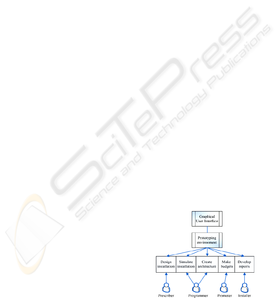
Figure 1: Environment features and their possible users.
ICINCO 2008 - International Conference on Informatics in Control, Automation and Robotics
176

Environment provides the following features:
designing a control installation independently any
technology; perform simulations to verify and
validate that our design meets users specifications;
create architecture in agreement to the chosen
technology for implementation; making budgets
with each technology; develop different types of
reports. These features will be used by their
respective actors who are involved in a control
installation: designers, integrators, property
developers, engineer... (See figure 1).
The installation design is the first task. First of
all, services (2) should be added then input and
output resources (4) should be added and connected
with their corresponding services.
Network design is simulated in order to
guarantee that design satisfies specification. This
simulation will be explained in next points. The
architecture creation task allows architecture
generation that will implement the design in a real
installation. This architecture is based on a
middleware (Valdivieso et al., 2007) (Fuster et al.,
2005) that provides communication among different
control technologies. The budget creation task
generates budgets from the technological design.
The reports development task allows generate some
types of reports: wired connections, devices
situation, etc.
4 SIMULATION
The environment is designed to perform simulations
from different abstraction levels. Simulations are
from functional layer (1), (2), structural layer (3), (4)
and (5) and technological layer (6). The functional
simulation is responsible for simulating the
behaviour of generic control network. With this
validation the generic device configuration and
connections can be ensured. The structural
simulation includes the functional, but adds new
features, like the real resources position and
installation regulation. The technological simulation
determines the real behaviour that the implemented
control network provides.
Simulation calculations are realized by an
external module that has been developed in Matlab /
Simulink. The communication between the
simulation calculations module and environment has
been done through a Java library called jMatLink
(Müller and Waller, 1999). It is responsible for
sending commands to Matlab. A library called jSCA
has been developed. It is responsible for
encapsulating Matlab commands for facilitate the
communication. The jSCA features are implemented
as methods which allow: create Matlab instances;
create, configure, and remove blocks in Simulink;
configure parameters simulation, and obtain the
simulation results. This library is a level above
jMatLink. The environment calls jSCA library and
this library calls jMatlink library.
Figure 2: Architecture that achieves communication
among Java application and Simulink.
The architecture that achieves the
communication among Java application and
Simulink is showed at figure 2. The first layer is the
own Trasgu that communicates with jSCA library in
order to use jMatlink library that allows
communication with matlab engine. It is daemon
that is listening matlab commands thrown by
jMatlink and uses own Simulink library for simulate.
4.1 Implementation
The environment has been implemented in Java and
uses an information system implemented in XML.
These XML files reflect information of the resources
that can be used in the installation and the
information about the current network. This
information is reflected from abstraction layers
defined at the model.
Environment presents distinct areas. Services
that the user can add to the network are at the top of
the window. Generic resources are on the left side of
the window and can be used in the design. Building
plant is on the centre. Services and resources can be
added to this area. Services (2) define their
behaviour based on inputs from input resources (4)
and provide outputs to output resources (4). These
functions are logical, arithmetical and comparison
operators. This specification is done in a form that
contains inputs, output and operators that allows
interconnect them. Figure 3 shows control network
designed at environment.
Simulation requires a parallel model from the
functional layer in Simulink. This model is
equivalent to the XML files defined in the
information system used by the environment. Each
resource defined in the environment is corresponded
by another defined in Simulink library created for
control network simulation. The Simulink model
consists in a block set formed by input blocks,
output blocks, input-output blocks, and connections
in order to establish a logic circuit. For this purpose
ENVIRONMENT FOR DESIGNING AND SIMULATING CONTROL NETWORKS AT DIGITAL HOME
177
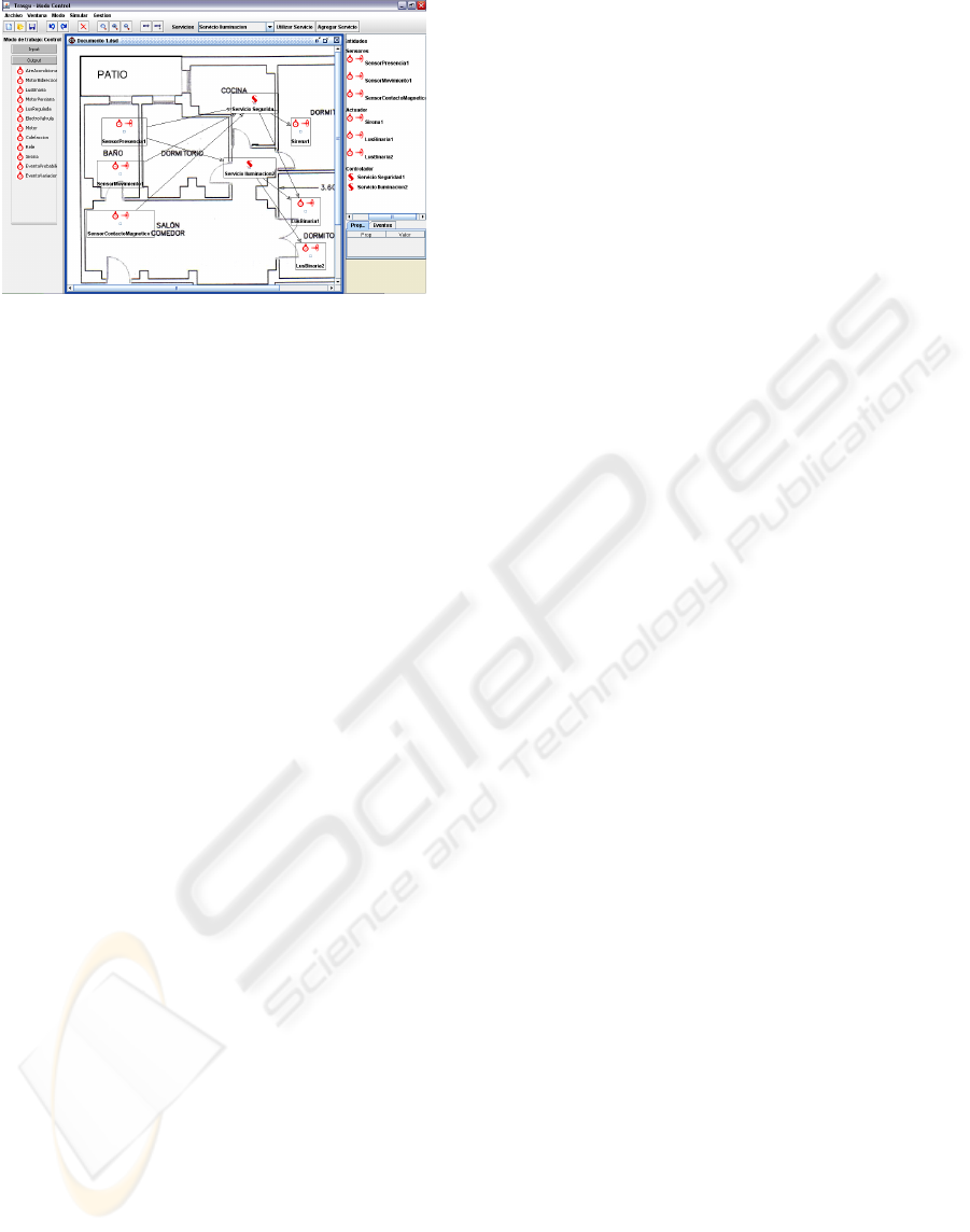
Figure 3: Network designed at environment.
there are two block types: discrete and continuous.
The discrete blocks are for digital devices, and
continuous are for analogic devices.
The simulation starts creating an equivalent
control network in Simulink. The corresponding
network blocks must be added to create the mdl file.
Parameters of each block are configured and
connections among blocks are created. The last step
is to add probability or schedules events for activate
sensors. Finally the mdl file is created and Simulink
executes the simulation and the environment reads
values from all Simulink network blocks and
represents them at environment.
5 CONCLUSIONS
This paper presents a design and simulation
environment of control networks in digital home.
The objective is to facilitate the tasks of designing
and validating control networks. A top-down
methodology is proposed, where technology
implementation choice is left to the end phase of
designing process. The environment kernel is the
control network model around different abstraction
layers: functional, structural and technological.
Simulation is presented as a new phase in
methodology of design control network. It reduces
costs and helps us to design effective and efficient
control networks.
The future work is aimed to deepening in aspects
of results generalization: new models for structural
and technological layers, simulation of technological
layer and interactive simulation module.
REFERENCES
Bravo, C., Redondo, M., Ortega, M.., and Verdejo, M.F.,
2006. Collaborative environments for the learning of
design: a model and a case study in Domotics.
Computers & Education, Vol. 46, No. 2, 152-173.
Denning, P. J., Comer, D. E., Gries, D., Mulder, C.,
Tucker, A., Turner, A. J., Young, P. R., 1989.
Computing as a discipline. Communications of the
ACM, Vol.32 No.1, 9-23
Fuster, A. and Azorín, J., 2005. Hogar digital. El camino
de la domótica a los ambientes inteligentes.I Encuentro
Interdisciplinar de Domótica 2005, pp 45-54
Fuster, A., de Miguel, G. and Azorín, J., 2005. Tecnología
Middleware para pasarelas residenciales. Hogar
digital. El camino de la domótica a los ambientes
inteligentes.I Encuentro Interdisciplinar de Domótica
2005, 87-102.
González, V. M., Mateos, F., López, A.M., Enguita, J.M.,
García M.and Olaiz, R., 2001. Visir, a simulation
software for domotics installations to improve
laboratory training, Frontiers in Education
Conference, 31st Annual Vol. 3, F4C-6-11.
Haenselmann, T., King, T., Busse, B., Effelsberg, W. and
Markus Fuchs, 2007. Scriptable Sensor Network
Based Home-Automation. Emerging Directions in
Embedded and Ubiquitous Computing, 579-591.
Jung, J., Park, K. and Cha J., 2005. Implementation of a
Network-Based Distributed System Using the CAN
Protocol. Knowledge-Based Intelligent Information
and Engineering Systems. Vol. 3681.
Kawamura, R. and Maeomichi, 2004. Standardization
Activity of OSGi (Open Services Gateway Initiative),
NTT Technical Review, Vol. 2, No. 1, 94-97.
Mellor, S., Scott K., Uhl, A. and Weise, D., 2004. MDA
Distilled, Principles of Model Driven Architecture,
Addison-Wesley Professional.
Min, W., Hong, Z., Guo-ping, L. and Jin-hua, S., 2007.
Networked control and supervision system based on
LonWorks fieldbus and Intranet/Internet. Journal of
Central South University of Technology, Vol. 14,
No.2, 260-265.
Müller, S. and Waller, H., 1999. Efficient Integration of
Real-Time Hardware and Web Based Services Into
MATLAB. 11
th
European Simulation Symposium and
Exhibition, 26-28.
Muñoz, J., Fons, J., Pelechano, V. and Pastor, O., 2003.
Hacia el Modelado Conceptual de Sistemas
Domóticos, VIII Jornadas de Ingeniería del Software y
Bases de Datos. Universidad de Alicante, 369-378
Newcomer, E. and Lomow, G., 2005. Understanding SOA
with Web Services. Addison Wesley.
Norton S. and Suppe F., 2001. Why atmospheric modeling
is good science. MIT Press. p. 88-133.
Rhee, S., Yang, S., Park, S., Chun, J.and Park, J., 2004.
UPnP Home Networking-Based IEEE1394 Digital
Home Appliances Control. Advanced Web
Technologies and Applications, Vol. 3007, 457-466.
Valdivieso, R.J., Sánchez, J.G., Azorín, J. and Fuster, A.,
2007. Entorno para el desarrollo y simulación de
arquitecturas de redes de control en el hogar. II
Internacional Simposium Ubiquitous Computing and
Ambient Intelligence.
ICINCO 2008 - International Conference on Informatics in Control, Automation and Robotics
178
