
REAL-TIME SYSTEMS SAFETY CONTROL CONSIDERING
HUMAN MACHINE INTERFACE
José Machado and Eurico Seabra
Mechanical Engineering Department, University of Minho, Campus of Azurém, 4800-058 Guimarães, Portugal
Keywords: Real-Time Systems, Safety Control, Human Machine Interface, Dependable Systems.
Abstract: In this paper it is presented the analysis of real-time industrial controllers when it is taken into account
human behavior in the use of fully automated industrial systems. It is intended to develop safe controllers
for these systems and make them robust against inappropriate utilizations by human operators. For the
attainment of our goals it is used a case study, where, based on a IEC 60848 specification, is deduced the
controller program. Further, it is elaborated the controller model, the Plant model and the Human Machine
Interface Model of the automated system. The obtained results are generalized for other similar systems
with the presented case study.
1 INTRODUCTION
Since the early eighties, the influence of the human
role and of the degree of the human implication in
the human-machine global performance (production,
safety,…) has been studied. Tom Sheridan defined
(Sheridan, 1984) the well-known degrees of
automation and their consequences. These defined
three degrees of automation and their consequences
are:
• In fully manual controlled systems, safety
totally depends on the human controller
reliability;
• An intermediate, state allows a task sharing
between the human operators and the
automated controlled systems; and,
• Fully automated systems reject the human
operator out of the control and that can
produce a lack of vigilance, a loss of skill and
can prevent him to assume all the
responsibility on the system. Therefore, the
system safety is almost totally linked to the
technical reliability.
In the study presented on this paper we will
focus on the third point related with the fully
automated systems. In the industrial controllers
analysis, it will be used simulation and formal
verification techniques to increase, together, the
safety of industrial controllers.
Among the several available techniques for the
industrial controllers analysis, Simulation (Baresi et
al. 2000, Baresi et al. 2002) and Formal Verification
(Moon 1994, Roussel and Denis 2002), can be
distinguished due to their utility. In the research
works on industrial controllers’ analysis, these two
techniques are rarely used simultaneously. In our
work, here presented, these two techniques are used
together and it is shown that exist some limitations
in the use of Simulation when compared with
Formal Verification. These limitations are
demonstrated in a context of studying the Human
Machine Interface (HMI) of real time industrial
systems. Some results that seam to be correct, using
Simulation, may not be correct when using Formal
Verification. This paper is focused in giving an
overview in the limitations of Simulation when
compared with Formal Verification in a context of
the HMI.
To accomplish our goals, in this work, the paper
is organized as follows. In Section 1, it is presented
the challenge proposed to achieve in this work.
Section 2 presents a general presentation of the case
study involving a system with two tanks filled and
emptied by the control of some on-off valves.
Further, it is presented the methodology to obtain the
controller program deduced from an IEC 60848 SFC
specification of the system’s desired behaviour.
Sections 3 and 4 are, respectively, devoted to the
modelling the plant and HMI. In section 5 are
presented the system behaviour analysis results and
269
Machado J. and Seabra E. (2008).
REAL-TIME SYSTEMS SAFETY CONTROL CONSIDERING HUMAN MACHINE INTERFACE.
In Proceedings of the Fifth International Conference on Informatics in Control, Automation and Robotics - SPSMC, pages 269-274
DOI: 10.5220/0001498602690274
Copyright
c
SciTePress
finally, in section 6 are presented some conclusions
and future work.
2 CASE STUDY
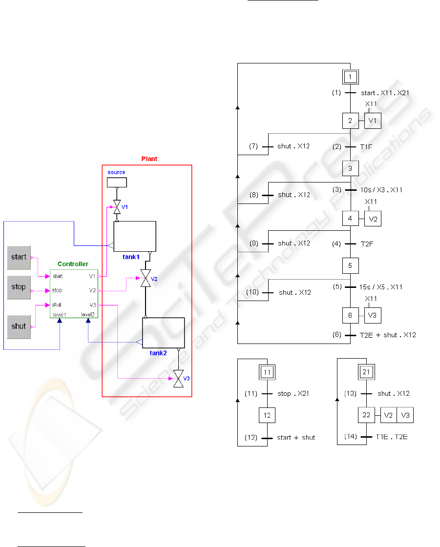
The case study, composed by two tanks and filling
and emptying on-off valves, is presented in figure 1.
Tank1 is filled by opening valve V1. When the level
of the tank1 becomes high, the valve V1 is closed.
After a waiting time of ten time units, valve V2 is
opened and the fluid flows from tank1 into tank2.
When tank1 is empty, valve2 is closed and, after
a waiting time of fifteen time units, valve3 is opened
and the fluid flows out of tank2. Finally when tank3
is empty, valve V3 is closed. In this work we
consider that one time unit is equal to one second.
Figure 1: Evaporator system: Closed-loop system
composed by controller and plant and start, stop and shut
buttons to interact with human behaviour.
Three buttons can influence the above normal
operation: start, stop and shut. In order to guarantee
the desired functioning of the system it is necessary
to simulate the following desired behaviors, traduced
by three system behavior properties:
• Property 1 (P1)
: In the beginning, when the
start button is pressed the system must start,
immediately, filling the tank 1.
• Property 2 (P2)
: Button “shut” is used to
shutdown the process. When the shut button is
pressed the system controller must reach the
initial state or the system must begin emptying
immediately the two tanks, in simultaneous.
• Property 3 (P3):
When the stop button is
pressed the system must stand in its actual
situation.
2.1 IEC 60848 Controller Specification
Figure 2: SFC specification of the controller.
As we use the Simulation and Formal Verification,
using different tools and intending to conciliate the
obtained results, we adopted a controller
specification that is the same for the basis of the
controller program in the two analysis techniques.
Thus, the controller specification was developed
in IEC 60848 SFC because it can be used as the
basis for the development of the Programmable
ICINCO 2008 - International Conference on Informatics in Control, Automation and Robotics
270
Logic Controller program (PLC), to be verified with
UPPAAL based on timed automata (Alur and Dill,
1990), and also it is the basis for the controller
program to be used by StateGraphs Modelica library
(Otter et al. 2005).
Table 1: Input/Output variables of the controller.
Inputs Outputs
Start – system start
stop – system stop
shut – system
shutdown
T1E – tank1 empty
T1F – tank1 full
T2E – tank1 empty
T2F – tank1 full
V1 – open valve1
V2 – open valve2
V3 – open valve3
The input and output variables of the controller
model are summarized on Table 1; minimum and
maximum level sensors of the tanks and the human-
machine interface buttons (start, stop and shut) are
controller program inputs and the on-off valves (V1,
V2 and V3) are controller program outputs.
In order to guarantee the desired behaviour for
the described system, a IEC 60848 SFC
specification is presented in Figure 2. As IEC 60848
SFC is a specification language (and not a
programming one), it is necessary to translate the
SFC specification, first to a StateGraph program,
presented in (Seabra and Machado, 2007) and,
second, to translate it into a program written in a
PLC programming language (in this case it will be
used the ladder language). This translation is done
using a methodology, having as base the
specification algebraic representation and
considering also the controller program behavior
presented at (Machado, 2006).
3 MODEL OF THE PLANT
In the plant modeling, first, the plant is modeled
with the Modelica programming language (Elmqvist
and Mattson, 1997) and simulated with the Dymola
software and, second, it is modeled by timed
automata to be used as input of the UPPAAL
software (David et al. 2003). The delays obtained, in
the simulation with the Dymola software, are used to
create the timed automata that are used on Formal
Verification with the UPPAAL tool.
3.1 Plant Modelling for Simulation
Purposes
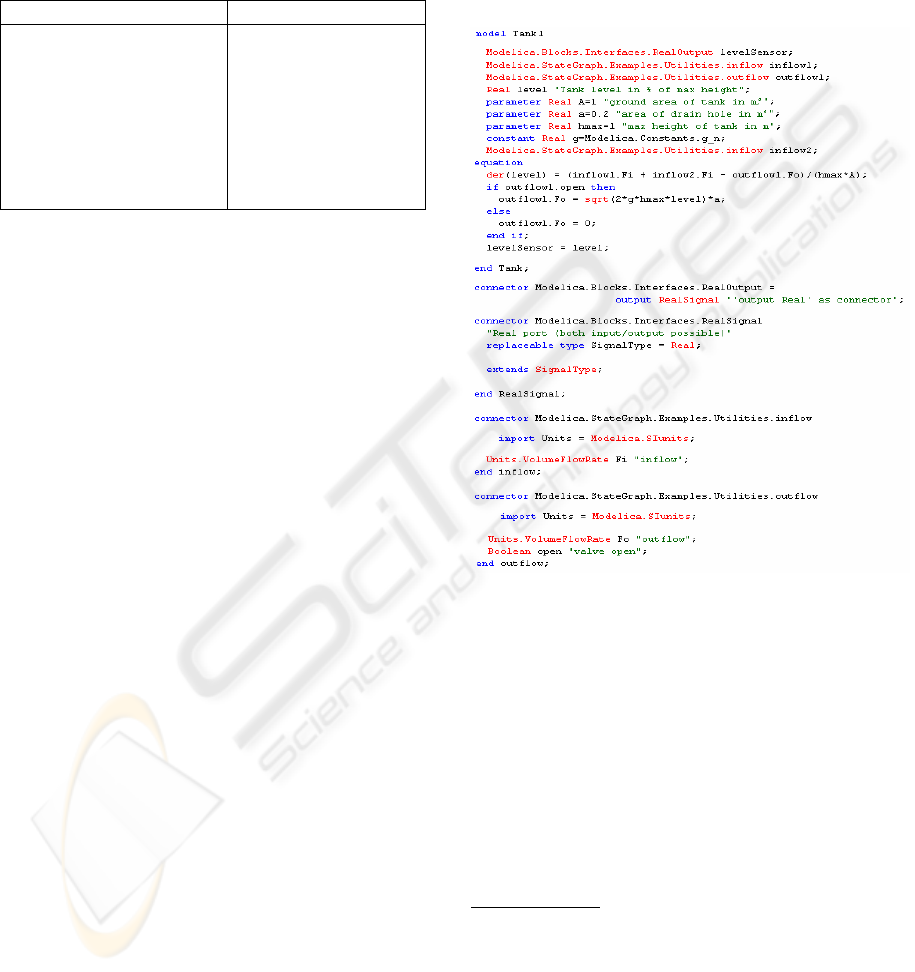
All the system was modeled. The tank1 model is
presented on this sub-chapter. Lets consider the case
of the tank 1 we have, for the Modelica
programming language the model presented in
Figure 3.
Figure 3: Modelica code for tank1 model.
The other physical parts of the system were
modeled (Seabra and Machado, 2007) but not
presented in this paper because is not part of the
goals of this paper.
3.2 Plant Modelling for Formal
Verification Purposes
For modeling the plant with formal verification
purposes there are considered the following modules
for the plant modeling: Tank1 and Tank2.
Model of tank1:
The obtained delays on simulation were used on
formal verification with UPPAAL. The
corresponding model of the tank developed in
UPPAAL for formal verification purposes is
presented in Figure 4.
REAL-TIME SYSTEMS SAFETY CONTROL CONSIDERING HUMAN MACHINE INTERFACE
271
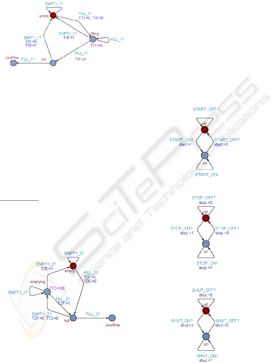
Figure 4: UPPAAL model of tank1.
We consider four states: empty models that tank1
is empty; filling models that the liquid is entering in
tank1; full models that tank1 is full; state overflow is
also considered, this is a possible state for the tank,
but describes an undesired behaviour. In this model,
it is also considered that the tank1 is emptied in a
very short time, when compared with the filling
time. We have considered this time null. It is for that
reason that the model goes from the full state
directly to the empty state, without an intermediate
state. The Boolean variables T1E and T1F are
associated with tank1.empty and tank1.full,
respectively. These variables represent the level
sensors’ signals sent by the sensors from the plant to
the controller. The maximum time for filling tank1 is
six time units.
Model of tank2:
The model of tank2 is presented in figure 5 and
the reasoning followed to obtain this model was the
same as presented before for obtaining the tank1
model. As empting tank1 is considered to take a
short (null) time, the filling of the tank2 is done in
the same conditions, since the liquid is transferred
from tank1 to tank2.
Figure 5: UPPAAL model of tank2.
Four states are considered: empty, full, emptying
and overflow which is a possible state for the tank,
but describes an undesired behavior. The variables
T2E and T2F have the same behavior on the tank2
model as the T1E and T1F described above on the
tank1 model. Empty tank2 takes, at maximum,
twenty-six time units.
4 MODELLING THE HUMAN
MACHINE INTERFACE
In this chapter are modelled the three buttons: start,
stop and shut. The models for these elements of the
(HMI) are presented in figures 6, 7 and 8.
For each HMI button the considered behaviours
are that each one can be in the state off or on. They
can change of state at any time, according the human
behaviour.
Figure 6: Model of the start button.
Figure 7: Model of the stop button.
Figure 8: Model of the shut button.
ICINCO 2008 - International Conference on Informatics in Control, Automation and Robotics
272

In the evolutions of the controller model it is
considered that it will be implemented into a PLC
with a scan cycle composed by three distinct phases:
Controller Inputs Reading (CIR), Controller
Computing (CCO) and Controller Outputs Updating
(COU).
The evolution of the controller model takes into
account the state changing of the HMI buttons at
each moment that it is in the CIR state. Any
changing of the HMI buttons state during the
evolution of the controller behaviour is not detected
by the controller model (as it is in the real behaviour
of the controller). Taking into account the
characteristics of the controller behaviour, the
characteristics of the plant behaviour and the
characteristics of the HMI behaviour, the properties
must be proved in the end of the evolution of the
controller model, after the Controller Outputs
Updating states.
5 SYSTEM BEHAVIOUR
ANALYSIS RESULTS
In the analysis of the system behaviour there were
used the two indicated techniques: the Simulation
and the Formal Verification.
It is pointed out that the system behaviors that
we intend to analyze, in this paper, are directly
related with possible human behaviors (correct or
incorrect) in the use of the automated system. There
are allowed, in the HMI models all possible human
behaviors with the three considered buttons.
The work presented here is a small part of a
larger developed work in the proof of properties in
real-time systems. The developed work in the
context of the controller behavior properties and the
global system behavior properties were presented,
respectively, in (Machado et al. 2007-a) and
(Machado et al. 2007-b).
The properties to prove, related with HMI, are:
• Property 1 (P1)
: In the beginning, when the
start button is pressed the system must start,
immediately, filling the tank 1.
• Property 2 (P2)
: Button “shut” is used to
shutdown the process. When the shut button is
pressed the system controller must reach the
initial state or the system must begin emptying
immediately the two tanks, in simultaneous.
• Property 3 (P3):
When the stop button is
pressed the system must stand in its actual
situation.
5.1 Simulation Results
Considering Simulation all properties are true.
As in this paper it is intended to show the
advantages of Formal Verification related with
Simulation, we will focus on Formal Verification
results discussion.
5.2 Formal Verification Results
Before presenting the formal verification results the
properties must be formalized using the UPPAAL
syntax, and, for that, we need a small part of TCTL
formalism (Alur et al. 1993 ). In the formulas below
which are all (possibly timed) invariants, A is the
universal quantifier on paths: for any path…, and [ ]
means always… The combination A [ ] means for
all states in the future…
There are considered, for the properties
formalization, the input and output variables of the
controller, the step variables of the controller SFC
program and the state of the controller model, where
are verified the properties according some rules
defined in (Machado, 2006). The considered state of
the controller model for the properties verification is
the Controller Outputs Updating state, COU.
For the properties formalization we have:
• P1: A[] !(COU && X1 && start)
• P2: A[] !((COU && !X22 && shut) || (COU
&& !X1 && shut))
• P3: A[] !(COU && X11 && stop)
After the formal verification tasks, the obtained
results are that all the properties are false.
5.3 Discussion of the Obtained Results
All the results, that are false in Formal Verification
analysis, are related with the controller behaviour
(Cyclic scan monitor of the PLC).
Indeed, in Simulation, this detail is not taken into
account but, in Formal Verification (because it is an
exhaustive technique!), these undesired behaviours
are detected and we can show that, with this
technique, the obtained results are exhaustive and
precise.
Detailing the results obtained for the Property 1
we can interpret the obtained trace with the
following sequence of human operator actions (see
figure 2):
In the initial situation, of the system, if the
human operator does not press the start button (as
expected!) but presses the stop button, the step 12 is
activated;
REAL-TIME SYSTEMS SAFETY CONTROL CONSIDERING HUMAN MACHINE INTERFACE
273

If, after that, the human operator presses the shut
button the step 22 is activated too;
Further, if the human operator presses the start
button the system does not start its normal behaviour
because the variable step X21 is not activated and
the step 1 remains active at least during a PLC
internal cycle.
For all the other properties the obtained results
(false) may be explained in the same way, when
analyzing the respective traces.
To solve this problem, there are many
possibilities. The simpler one seems to consider
actuation priorities for the three buttons considered.
These priorities must be included on the controller
program specification and, consecutively, in the
controller program implementation.
6 CONCLUSIONS AND FUTURE
WORK
With our study it has been possible to show that
some problems can occur if the development of safe
industrial controllers, for fully automated systems,
are not developed taking into account some possible
incorrect behaviours of human operators.
These possible undesired system behaviours can
be detected, only, if it is used the Formal
Verification technique; the Simulation technique is
not sufficient.
The fully automated systems safety is almost
totally linked to the technical reliability of the
system and it must be guaranteed that some incorrect
possible behaviours of the human operators do not
compromise these systems’ safety and
dependability.
ACKNOWLEDGEMENTS
This research project is carried out in the context of
the SCAPS Project supported by FCT, the
Portuguese Foundation for Science and Technology,
and FEDER, the European regional development
fund, under contract POCI/EME/61425/2004 that
deals with safety control of automated production
systems.
REFERENCES
Alur R., Dill D. L., 1990. Automata for Modeling Real-
Time Systems. Proceedings of the 17th Int. Coll.
Automata, Languages, and Programming (ICALP'90),
Warwick University, England, July 1990, Vol. 443,
Lecture Notes in Computer Science, Springer.
Alur R., Courcoubetis C., Dill D. L, 1993. Model-
Checking in Dense Real-Time. Information and
Computation, vol. 104, n_ 1, p. 2-34.
Baresi L., Mauri M., Monti A., Pezzè M., 2000.
PLCTOOLS: Design, Formal Validation, and Code
Generation for Programmable Controllers. Special
Session at IEEE Conference on Systems, Man, and
Cybernetics. Nashville USA.
Baresi L., Mauri M., Pezzè M., 2002. PLCTools: Graph
Transformation Meets PLC Design. Electronic Notes
in Theoretical Computer Science 72 No. 2.
David A., Behrmann G., Larsen K. G., Yi W., 2003. A
Tool Architecture for the Next Generation of
UPPAAL. Technical Report n. 2003-011, Department
of Information Technology, Uppsala University, Feb.
20 pages.
Elmqvist E., Mattson S., 1997. An Introduction to the
Physical Modelling Language Modelica. Proceedings
of the 9th European Simulation Symposium, ESS'97.
Passau, Germany.
Machado J., 2006. Influence de la Prise en Compte d’un
Modèle de Processus en Vérification Formelle des
Systèmes à Evénements Discrets. PhD Thesis in
cooperation between the University of Minho and
École Normale Supérieure de Cachan; School of
Engineering, University of Minho, June.
Machado J., Seabra E., Campos J., Soares F., Leão C.,
Silva J., 2007-a. Simulation and Forml Verification of
Industrial Systems Controllers. Proceedings of 19
th
Edition of the International Congress of Mechanical
Engineering (COBEM’2007), Brazilia, Brazil, 5-9
th
November.
Machado J., Seabra E., Soares F., Campos J., 2007-b. A
new Plant Modelling Approach for Formal
Verification Purposes. Proceedings of the 11
th
IFAC/IFORS/IMACS/ IFIP Symposium on Large Scale
Systems: Theory and Applications. Gdansk, Poland.
Moon I. 1994. Modeling programmable logic controllers
for logic verification. IEEE Control Systems, 14, 2,
pp. 53-59
Otter M., Årzén K., Dressler I., 2005 StateGraph - A
Modelica Library for Hierarchical State Machines.
Modelica 2005 Proceedings.
Roussel M., Denis B., 2002. Safety properties verification
of ladder diagram programs. Journal Européen des
Systèmes Automatisés, vol. 36, pp. 905-917
Seabra E., Machado J., 2007. Simulation of Real Time
Systems Behavior Considering Human-Machine
Interface. In Proceedings of the 6
th
EUROSIM
Congress on Modelling and Simulation, Federation of
European Simulation Societies, September 9-13,
Ljubljana, Slovenia.
Sheridan, T. B., 1984. Supervisory Control of Remote
Manipulators Vehicules and Dynamic Processes:
Experiments in Command and Display Aiding, In
Advances in Man-Machine Researches, Vol.1.
ICINCO 2008 - International Conference on Informatics in Control, Automation and Robotics
274
