A DISTRIBUTED FAULT TOLERANT POSITION CONTROL
SYSTEM FOR A BOAT-LIKE INSPECTION ROBOT
Christoph Walter, Tino Krueger and Norbert Elkmann
Fraunhofer Institute for Factory Operation and Automation
Sandtorstrasse 22, 39106 Magdeburg, Germany
Keywords: Distributed control system, fault tolerance, self-tuning controller.
Abstract: Here we present the position control system of a swimming inspection robot for large under-ground con-
crete pipes that are partially filled with wastewater. The system consists of a laser-based measurement sub-
system for position determination and a mechanical rudder to move the robot laterally within the pipe. The
required software components are implemented as services following a CORBA-based architecture. To
automatically adapt the position control system to different environment conditions, a self-tuning controller
is used. The controller has hybrid requirements regarding latency and interarrival times of computed posi-
tion values. In this contribution, we describe the architectural support for this application as well as how the
system deals with excessive latencies due to transient overload.
1 INTRODUCTION
The Emschergenossenschaft based in Germany is
currently planning the Emscher sewer system, ar-
guably the largest residential water management
project in Europe in years to come. The new em-
scher sewer will show a total length of 51 km and
diameters between 1.4 and 2.8 m in depths up to 40
m under surface. The Emschergenossenschaft en-
gaged the Fraunhofer Institute for Factory Operation
and Automation (IFF) in Magdeburg, Germany, as
the general contractor to develop automatic inspec-
tion and cleaning systems to meet the requirements
imposed by legal guidelines.
Large under-ground concrete pipes that are par-
tially filled with wastewater are a hazardous envi-
ronment for man. Nevertheless, inspection of such
pipes must be performed on a regular basis. Many of
today’s remote controlled inspection systems for
underground sewer pipes consist of a single TV-
camera and are designed for pipe diameters below
one meter. The recent development of automatic
inspection systems (Elkmann et al., 2005) equipped
with advanced sensors makes it possible for an op-
erator to perform this task from an outside position
even for pipes with a diameter between 1.4 to 2.8
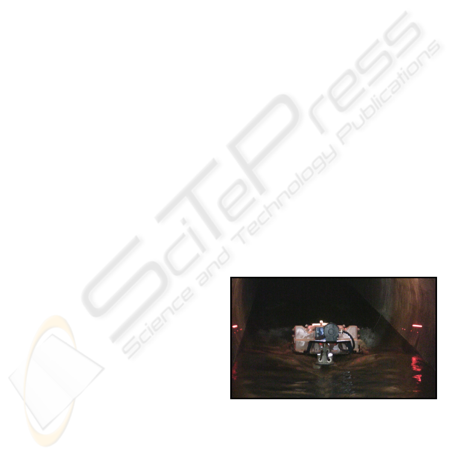
meters. The cable-guided damage surveying system
(SEK) (see Fig. 1) was developed to be a versatile
and easy-to-use tool to detect various kinds of dam-
ages above and underneath the water-line with high
accuracy.
The inspection process is largely automated
(Elkmann et al., 2006) and supervised by an operator
from within a service-vehicle outside of the sewer.
To ensure an optimal inspection result the system
must acquire data from a centered position.
Figure 1: The cable-guided damage surveying system
within a sewer pipe.
For this reason, it is our goal to keep the robot near
the center of the pipe during the data acquisition
phase. We must also deal with different environment
conditions. These include water level, flow velocity
and pipe diameter. A traditional controller with fixed
parameter set was unable to maintain a stable posi-
28
Walter C., Krueger T. and Elkmann N. (2008).
A DISTRIBUTED FAULT TOLERANT POSITION CONTROL SYSTEM FOR A BOAT-LIKE INSPECTION ROBOT.
In Proceedings of the Fifth International Conference on Informatics in Control, Automation and Robotics - ICSO, pages 28-34
DOI: 10.5220/0001489100280034
Copyright
c
SciTePress

tion depending on the current conditions. To tackle
this problem the position control system of the robot
was fitted with a self-tuning controller that is able to
identify model based control parameters prior to data
acquisition.
The main part of the controller was implemented
using a software programmable logic controller
(PLC). The input to the controller is the current lat-
eral position relative to the pipe axis. An iterative
algorithm using data from various sensors, mainly
three banks of laser distance sensors, determines the
position. The PC-based implementation of this algo-
rithm has an unknown worst-case execution time
(WCET). The actual execution time is depending on
the internal state of the software as well as on the
current input data. Further delay stems from the
transmission of data over the Ethernet network be-
tween PLC and PC as well as from the scheduling
scheme of the calculation task. While the actual con-
troller is robust against certain latency and jitter of
the arrival of position data, we must consider cases
when position data does not arrive in time. This may
happen due to unusual long execution time of the
position determination algorithm or due to transient
overload of the communication channel.
Another challenge is the second part of the self-
tuning controller, which performs the identification
of the system’s behavior and which derives an ade-
quate control parameter set. The algorithm used here
is very sensitive to jitter of the interarrival times of
position measurements and to missing samples.
An architectural approach for solving both prob-
lems is described in section 3. In section 4, the ac-
tual controller is presented in more detail. Section 5
briefly discusses the dynamic quality of service ap-
proach used to avoid failure in case of transient
overload.
2 RELATED WORK
Realizing time critical applications using complex
distributed systems is a challenging task. On one
hand, considerable work has been done to introduce
time constraints or timely predictable behavior. On
the other hand, a number of approaches have been
published to relax time constraints of certain appli-
cations by introducing fault tolerance mechanisms.
In the field of communication middleware, the
Object Management Group (OMG) has released
extensions to the known CORBA-specification to
extend it with real-time features (Wolfe et al., 1997).
The primary focus here is on the introduction of
priorities when executing method calls, which re-
quires appropriate system software support. Soft-
ware libraries implementing this standard were also
made available (Schmidt et al., 1998).
To relax time constraints, approaches that try to
balance quality of service and required computation
time were considered. This includes the classical
“anytime” (Dean, Boddy, 1988) or “flexible”
(Hendler, 1989) algorithms, where quality of service
can be dynamically traded against shorter computa-
tion times. This scheme can be used to ensure the
timeliness of computations. The authors of (Nett et
al., 1998) have also dealt with meeting task dead-
lines. They use a dynamic task scheduling scheme
with detection and handling of timing faults. Faults
are handled via a task-pair strategy with invocation
of an alternative exception task in case of a timing
fault.
3 DATA ACQUISITION AND
PROCESSING
3.1 Modeling Data Flow using Services
We developed a service oriented CORBA-based
software architecture focusing on data flow and dis-
tributed processing. In our system, an application is
constructed by combining software modules that
provide functionality to other modules via a generic
interface. The modules may be arbitrarily distributed
over a number of computers in a network. The inter-
face of the services is data centric. It allows services
to offer data via named buffers to other services or
clients. Each buffer represents a time series of spe-
cific data objects (see Fig. 2). A service can repre-
sent a data source (e.g. a sensor), a processing mod-
ule or a data consumer (e.g. an actuator, a database,
or a GUI). Services that represent sensors or sensor
systems may provide data that represents a single
measurement, a time series of measurements, a vec-
tor, an image, or any other types of data that are
generated by the sensor system. Other services may
not provide sensor data but processing results.
By connecting the services via the pub-
lish/subscribe paradigm the data flow of the applica-
tion is modeled. In this communication model, the
services play different roles. The module providing
data is called the service provider. The data con-
sumer is called the service client. Please note that in
our system a client does not subscribe to specific
data elements but to notifications on when such ele-
ments become available.
A DISTRIBUTED FAULT TOLERANT POSITION CONTROL SYSTEM FOR A BOAT-LIKE INSPECTION ROBOT
29
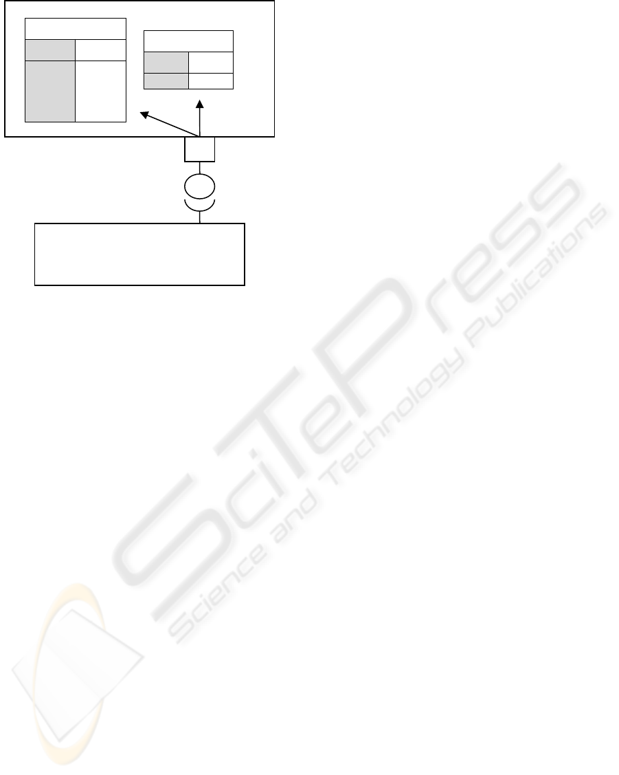
Figure 2: A service provider offers data buffers to clients
via a generic interface.
The data objects that are being exchanged between
services satisfy a given scheme. They consist of bi-
nary data and metadata in XML syntax. The most
important element of the metadata is the timestamp,
which indicates the recording time of the original
data. The timestamp acts as a key for the data object
within the given data buffer. The binary data can
contain information in any format. A client can re-
quest individual data elements or arbitrary blocks of
data elements from a buffer. This is achieved by
sending structured queries with a simple syntax to
the accordant service. The client can then process
these data items and/or eventually offer the results to
further clients. The foundation of the used time-
stamps is the Newtonian time model. Timestamps
are generated based on synchronized local clocks. A
simple clock synchronization is carried out via the
network by a dedicated service. The accuracy of
synchronization between time-server and any client
is better than 100 µs. This is well below the shortest
interarrival times of data elements in our application.
It was achieved using common PC-hardware, Giga-
bit-Ethernet, and a Windows NT-based operating
system. Accuracy may be improved by using more
sophisticated clock synchronization algorithms.
3.2 Implementation of Position
Determination
Determining the position of the robot is of great im-
portance. Knowledge of the position is not only re-
quired for position control, but also to process and
interpret other sensors’ data. This includes the regis-
tration of images from a high-resolution photo-
graphic camera system, the analysis of data from an
ultrasonic underwater scanner, the determination of
the magnitude of corrosion and incrustations, or the
precise measurement of possible deviation of the
position of individual pipe segments. These tasks
cannot be performed without knowledge of the pose
of each sensor during data acquisition.
The heart of the position determination subsys-
tem is an algorithm that was specifically developed
for this purpose. It is implemented as a service (the
position determination service; PDS). It is based on
the measurements of a number of laser ranging sen-
sors plus an inclination sensor. A discussion of the
exact procedure can be found in (Elkmann et al.,
2006).
Measurements from the laser sensors are ac-
quired by the onboard PLC. The PLC is imple-
mented in software on an embedded PC and tightly
coupled with an interface service (IS). The IS has
access to the PLC’s memory and is configured to
insert time-stamped measurements into a buffer
queue at a rate of 100 Hz. This rate is consistent
with sensor capabilities and sufficient for our appli-
cation.
The PDS is notified of the arrival of new data
elements in the IS’s buffer. Its goal is to process all
data elements that are produced by the IS. To do this
the PDS uses the following strategy of data access:
Upon notification of a new data element, it asks the
IS for all elements that succeed the last element the
PDS has already processed. This is done via a single
“get”-operation. By using this technique, it is possi-
ble for the PDS to catch up in case of a previous
transient overload. For each received data element,
the system’s position is calculated and eventually
made available for further processing by other cli-
ents.
4 SELF-TUNING CONTROLLER
4.1 Controller Design
One challenge in the context of stable data acquisi-
tion between real time and non-real time systems
(hybrid systems) is the implementation of non-linear
controllers. This chapter describes the motivation of
using a non-linear controller in this area. In addition,
it gives a short introduction of calculating them.
When travelling through a partially filled sewer,
the position of the SEK is controlled by a rudder arm
mounted on top of the robot. The rudder can be
<< service >>
<< service client >>
buffer A
time data
t
0
t
1
…
t
n
d
0
d
1
…
d
n
buffer B
time data
… …
ICINCO 2008 - International Conference on Informatics in Control, Automation and Robotics
30
turned relative to the longitudinal axis of the pipe. In
turn, buoyancy forces the SEK to change its posi-
tion. Due to disturbances, a controller has to be inte-
grated for closed-loop navigation. Self-tuning con-
trollers belong to the denomination of adaptive con-
trollers. They are used to fit the plant on a variable
environment. In fact, the flow velocity of the waste-
water, the water level, and the pipe diameter may
change depending on the actual sewer and on current
conditions like the time of day or the weather situa-
tion. This motivates to use adaptive controllers for
the robot. The benefit of adaptive controllers com-
pared to fixed structure designs is the broad field of
applications. Here we will focus on the self-tuning
controller as a substitute of indirect adaptive control-
lers.
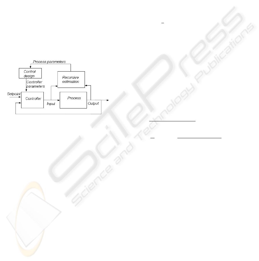
Intermediate instances are required for the calcu-
lation of the controller parameters (see Fig. 3).
Figure 3: Schematic diagram of a self-tuning controller.
The calculation of a self-tuning controller contains
the following steps:
Recursive estimation of process parameters
(system identification)
Suitable determination of a control law with ad-
justable parameters
Calculation of controller parameters based on
the desired closed-loop system
Update the parameters using the IS
The advantage of this method comprises the possi-
bility to secure each step of calculation before the
controller parameters are used. In addition, the
closed loop can be pushed to a desired behavior
while the parameters of the plant are changing.
The plant is depicted by a discrete autoregressive
moving average with an extra input model
(ARMAX-Model) of fourth-order. The advantage of
ARMAX-Models compared to simpler models is the
adequate freedom in describing the properties of the
disturbance term.
That gives the model:
)3(...)()3(...)1(
)3(...)1()(
3131
31
−+++−+−
=−++−+
tectectubtub
tyatyaty
(1)
with
].........[
313131
ccbbaa
=
θ
(2)
where y(t) is the plant output, u(t) is the control in-
put and e(t) the prediction error. In this case, the
least–squares criterion:
2
1
))()((
1
)(
∑
=
−
−=
t
i
Tit
iiy
t
tV
θϕλ
(3)
is being used to identify the transmission behavior of
the process. The parameters are time varying in a
small range during operation. Hence, it is desirable
to base the identification on the most recent data
rather than on the older data. This can be achieved
by exponential discounting (λ) of old data. Then, it
can be shown (Lennard Ljung, 1999) that the ex-
tended recursive least square scheme (ERLS) be-
comes:
⎟
⎟
⎠
⎞
⎜
⎜
⎝
⎛
−+
−−
−−=
+
=
−+=
)()1()(
)1()()1(
)1(
1
)(
(t))1)-(t)P(t (
(t)1)-P(t
L(t)
])1( (t) - L(t)[y(t) 1)-(t )(t
T
T
ttPt
tPttP
tPtP
t
T
T
ϕϕλ
ϕ
λ
ϕϕλ
ϕ
θϕθθ
(4)
Using ERLS it is advisable to consider the persistent
excitation in view of convergence of the parameter
estimation. In this step, the indirect method permits
to prove the estimated process parameters on sepa-
rate recorded test series. If the verification is suc-
cessful, the calculation of the controller parameter is
performed.
Fig. 4 depicts exemplary the change of positions
predicted by a calculated model towards measured
data. The rudder angle as input to the ERLS was
oscillating between minus five and five degrees. The
calculated model is afterwards the starting point for
the controller design.
The idea regarding the controller design is to
compensate the plant with the inverse system and a
desired transmission behavior.
A DISTRIBUTED FAULT TOLERANT POSITION CONTROL SYSTEM FOR A BOAT-LIKE INSPECTION ROBOT
31
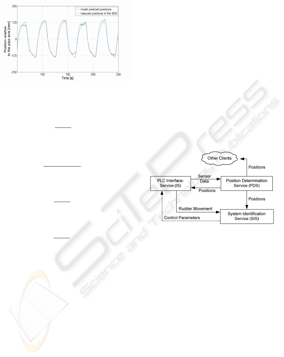
Figure 4: Measured and predicted positions of the SEK.
Assuming that the desired close loop behavior as
shown in equation 5 where z-1 is backward shift
operator.
)(
)(
)(
1
1
1
−
−
−
=
zA
zB
zM
)
)
(5)
The actual closed loop is:
)()(1
)()(
)(
11
11
1
−−
−−
−
+
=
zSzK
zSzK
zG
(6)
with the controller:
)(
)(
)(
1
1
1
−
−
−
=
zC
zD
zK
(7)
and the plant behavior:
)(
)(
)(
1
1
1
−
−
−
=
zA
zB
zS
(8)
The suitable controller law is then given by equation
9 without solving a Diophantine equation.
)(zB)A(z )D(z
-1-1-1
)
=
))(zB-)(zA)(B(z )C(z
-1-1-1-1
)
)
=
(9)
In terms of the causality of the controller law, we get
the following conditions for the implementation:
The transmission behavior of the plant has to be
stable, respect to the inverse implementation
in the controller law.
The polynomial of the decoupled model
)(zB-)(zA
-1-1
)
)
should only have zeros within
the unit circle.
The estimated plant model should not include a
minimum phase system or must be corrected
because of the stability of the open loop.
The controller law has to be causal.
The calculated controller is therefore less sensitive
to noise compared to other designs like the pole
placement variant, which is described by (Aström,
Wittenmark, 1992).
4.2 Implementation
The self-tuning controller was implemented in the
form of two main modules. The first module is the
actual controller. It runs as a real-time task within
the onboard PLC. Position-data is fed into it by the
IS as described in section 3.2. The IS acts also as a
client similar to the PDS but with a different strategy
of data access: The controller doesn’t want to proc-
ess all data elements that are produced by the PDS,
but needs the most recent one. For this reason the IS
upon notification of new data requests the most re-
cent data element from the PDS and feeds it into the
PLC.
Figure 5: Structure and data flow of controller implemen-
tation.
The second module is a service, which computes the
control parameter set (system identification service;
SIS). It needs two kinds of data elements as input:
(1) all sampled rudder arm angles during the system
identification process and (2) the corresponding sys-
tem position. The arrival of these data is not time
critical but it is necessary that all samples are being
processed. It therefore uses a similar data access
strategy as the PDS to gather all data elements that
describe the rudder movement from the IS. Further-
more, it requests for each such element the two clos-
est system positions from the PDS and interpolates
between them to get the corresponding system posi-
tion. Requesting closest elements given a certain
timestamp is another feature of the data-access
mechanism of our architecture. After the SIS has
collected enough data, it can compute the control
parameters and send them to the main control mod-
ule via the IS. The described data flow is shown in
Fig. 5.
ICINCO 2008 - International Conference on Informatics in Control, Automation and Robotics
32

5 DYNAMIC QUALITY OF
SERVICE
Even though we have successfully implemented the
system identification part of the controller as a non-
real-time service while guarantying the required data
quality, the actual controller may still suffer from
excessive latencies in the arrival of position data
from the PDS. This is because of (1) the iterative
algorithm used in the PDS and (2) because of large
latencies in the communication between the distrib-
uted services due to transient overload of the com-
munication channel.
To avoid system failure in such cases we inte-
grated a dynamic quality of service approach that
uses the timestamps of the position data available to
the controller implemented in the PLC to determine
the age of that data. If a certain age is exceeded, the
controller uses an alternative position that it com-
putes by a simple prediction mechanism based on
the last known positions. This fall back mechanism
is triggered if the position data available to the PLC
becomes older then 90 ms. While this is a crude
method and could easily be improved by using a
more accurate model based approach, it is sufficient
to deal with short disruptions of communication. If
however the position data becomes older then 900
ms, the controller is put into a safe state. In this
state, the rudder is moved into centered position,
which is the state that most unlikely causes a colli-
sion with the wall. The controller resumes as soon as
position data not older then 90 ms becomes available
again.
We performed experiments with a prototypic im-
plementation of the system under operating condi-
tions. To determine the actual interarrival times of
data produced by the PDS, we used a test-client that
was consuming position data in the same way as the
IS. In Fig. 6, the interarrival times recorded by the
test-service are shown. Well under 5 percent of the
position values arrived slightly later then usual. Less
then 1 percent of that were delayed more than 90 ms.
When that happened, approximately 50 percent were
delayed more than 900 ms.
Figure 6: Interarrival times of position data at Test-
Service.
When observing the behavior of the robot during the
experiment, no significant deviation from the ideal
position could be noticed. The system maintained
position near the center of the pipe when missing the
90 ms deadline. This was also the case when briefly
missing the 900 ms deadline. This can be attributed
to the fact that we only had small turbulences that
required only slight corrections by the position con-
trol system. However, we expect that missing the
900 ms deadline may have a significant effect in
case of more severe turbulences.
6 CONCLUSIONS
Here we presented an application of a distributed
control system for position control of a boat-like
inspection robot for partially filled sewer pipes. We
discussed the hybrid requirements of an advanced
self-tuning controller regarding timeliness and inter-
arrival times of its input data. We presented a
scheme for detecting and handling excessive time
delays to prevent system failure by using dynami-
cally reduced quality of the position controller. It
was also discussed, how the controller was inte-
grated into a non-real-time service oriented software
system. We conclude that in case of our application
it is feasible to use soft- or non-real-time compo-
nents in the control loop. Prerequisites are (1) a de-
terministic data acquisition with time stamping and
(2) a hard-real-time controller core with fault toler-
ance mechanisms.
REFERENCES
Elkmann N., Reimann B., Schulenburg E., Althoff H.,
2005. Automated inspection system for large under-
ground concrete pipes under operating conditions.
A DISTRIBUTED FAULT TOLERANT POSITION CONTROL SYSTEM FOR A BOAT-LIKE INSPECTION ROBOT
33

In Proc. International Conference on Field and Ser-
vice Robotics.
Elkmann N., Kutzner S., Saenz J., Reimann B., Schultke
F., Althoff H., 2006. Fully automatic inspection sys-
tems for large underground concrete pipes partially
filled with wastewater. In Proc. of International Con-
ference Intelligent Robots and Systems (IROS06).
Wolfe V. F., DiPippo L. C., Cooper G., Johnston R.,
Kortmann P., Thuraisingham B. M., 1997. Real-Time
CORBA. In Proc. of the Third IEEE Real-Time Tech-
nology and Applications Symposium.
Schmidt D. C., Levine D. L., Mungee S., 1998. The De-
sign of the TAO Real-Time Object Request Broker. In
Computer Communications 21(4), p. 294-324
Dean T. L., Boddy M., 1988. An analysis of time-
dependent planning. In Proceedings of the Seventh Na-
tional Conference on Artificial Intelligence, Minnea-
polis, Minnesota, p. 49-54.
Hendler J. A., 1989. Real-time planning. In Working Notes
of the AAAI Spring Symposium on Planning and
Search, Stanford.
Nett E., Gergeleit M., Mock M., 1998. An adaptive ap-
proach to object-oriented real-time computing. In Pro-
ceedings of ISORC'98, p. 342-349.
Ljung L., 1999. System Identification, PTR Prentice Hall
Astrom K., Wittenmark B., 1992. Adaptive Control, Pear-
son Education
ICINCO 2008 - International Conference on Informatics in Control, Automation and Robotics
34
