
FLEXIBLE ROBOT-BASED INLINE QUALITY MONITORING
USING PICTURE-GIVING SENSORS
Chen-Ko Sung, Andreas Jacubasch and Thomas Müller
Fraunhofer Institute IITB, Fraunhoferstrasse 1, 76131 Karlsruhe, Germany
Keywords: Multi sensors, wide- and short-range sensors, intelligent sensors, sensor magazine, object detection and
localization, learning-capable evaluation processes, topography, visual serving, flexible inline quality
monitoring, real-time processing, robot, dynamic and automatic path planning, large-area production.
Abstract: As part of the ROBOSENS project, the IITB developed and tested a new four-step concept for multiple
sensor quality monitoring. The robot-based system uses an array of test-specific short-range and wide-range
sensors which make the inspection process more flexible and problem-specific. To test this innovative inline
quality monitoring concept and to adapt it to customized tasks, a development and demonstration platform
(DDP) was created. It consists of an industrial robot with various sensor ports - a so-called “sensor
magazine” - with various task-specific, interchangeable sensors and a flexible transport system.
1 INTRODUCTION
A substantial reason for the hesitant use of picture-
giving sensors for the monitoring of inspection is the
insufficient flexibility of the used monitoring
concepts in relation to changing setting of tasks. At
present either one (user-specific) sensor or sensors
with static arrangement for a certain task of
inspection are used. This rigid approach is
unsuitable for the inspection of variant products.
Robots with multiple intelligent sensors will be
increasingly used in the future for demanding
production and assembly tasks. An especially
attractive area of application is the inline quality
monitoring of complex, large-area production parts
such as the aircraft fuselage (see Figure 1) or parts
of the bodies of road and rail vehicles. For example
hundred different mounting parts on an aircraft
fuselage (about 4 m x 10 m in size) must be
inspected, whether proper parts have been attached
correctly.
The presented new four-step concept (see Figure
2 and sections 2-5) has been developed and realized
at IITB for the flexible inline quality monitoring
(Sung and Kuntze, 2006) with the following
characteristics:
• Multiple sensor inline quality monitoring of
large complex manufacturing parts;
• Complete quality assurance with minimum
inspection expenditure;
• Large flexibility regarding frequently changing
test tasks;
• On-line ability by minimization of the testing
period.
All sensors are placed on a sensor magazine (see
Figure 1) and are ready to use immediately after
docking on the robot arm. The calibration of all
sensors and the hand-eye calibration have to be done
before the object localization task starts.
A special transport system like a monorail
conveyor will probably be needed for the
transportation of large objects. Such transport
systems do not allow a precise positioning. The test
object is free-hanging over the ground.
2 LOCALIZATION OF UNFIXED
INDUSTRIAL TEST OBJECTS
As the first step of the presented quality monitoring
chain, the exact position of a production piece is
determined with a wide-range picture-giving sensor
(see Figure 1), which is - depending on the object
size - mounted in an adequate object distance, i.e.
not necessarily fixed on an inspection robot's end-
effector.
A marker-less localization calculates the exact
object position in the scene. This procedure is based
only on a 3D CAD-model of the test object or at
297
Sung C., Jacubasch A. and Müller T. (2008).
FLEXIBLE ROBOT-BASED INLINE QUALITY MONITORING USING PICTURE-GIVING SENSORS.
In Proceedings of the Fifth International Conference on Informatics in Control, Automation and Robotics - ICSO, pages 297-301
DOI: 10.5220/0001486802970301
Copyright
c
SciTePress
least a CAD-model which represents a composition
of some of its relevant main parts. The CAD-model
contours are projected into the current sensor images
and they are matched with sub-pixel accuracy with
corresponding lines extracted from the image
(Müller, 2001).
Figure 3 shows a localization example. The
CAD-model projection is displayed in yellow and
the object coordinate system in pink color. The red
pixels close to the yellow projection denote
corresponding image line pixels which could
automatically be extracted from the image plane.
The calculated object pose (consisting of three
parameters for the position in 3D scene space as well
as three parameters for the orientation, see the red
text in the upper part of the figure) can easily be
transformed into the global scene coordinate system
(displayed in green color).
Known test zones for detail inspection as well as
associated sensor positions and orientations or
required sensor trajectories (cf. section 3 and 4) can
be defined with respect to the object coordinate
system in an inspection preceding step. All the
object based coordinates will be transformed online
into the global scene coordinate system or the robot
coordinate system with respect to the localization
result, i.e. with respect to the position and
orientation of the test object in the scene. The red, T-
shaped overlay in Figure 3 shows an example for an
optimal 3D motion trajectory (see the horizontal red
line which is parallel to the object surface) together
with the desired sensor's line of sight with respect to
the object surface (the red line which points from a
position in the middle of the trajectory towards the
test object).
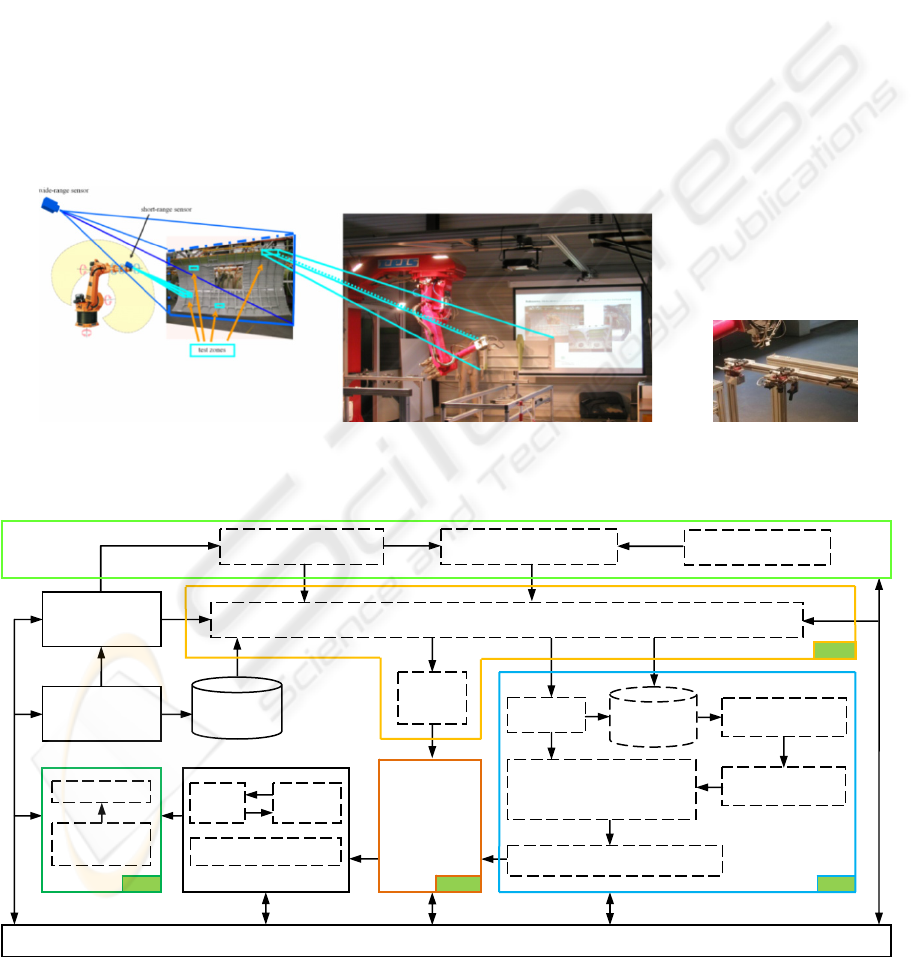
Figure 1: Quality monitoring of aircraft fuselages with wide- and short-range inspection sensors. Left: Test station and test
environment. The movement of production pieces is carried out by monorail conveyors which do not allow precise
positioning. Middle: Development and demonstration platform (DDP). Right: Sensor magazine.
Figure 2: System overview. A new four-step concept for the flexible inline quality monitoring.
3D view-based virtual
object image
Projected 2D view-
based object image
Robot control system
3D Scan Data /
CAD-model
Image acquisition
with wide-range
camera
Known test
zones
2D view-based
object images
Segmentation
Image processing (comparison,
morphological operations and
feature analysis)
Docking short-range sensor
System control
Visual-
Servoing
Split-beam sensor
Detection of test zones (Anomalies)
Step 2
Localization of unfixed test object (calculation the object pose)
Step 1
Sensor calibration Hand-eye calibration
Robot calibration
Robot
movements
Step 4
Logical / metric
inspection
OK / NOK
Time-optimal
dynamic path
planning
Travelling salesman
problem
Step 3
ICINCO 2008 - International Conference on Informatics in Control, Automation and Robotics
298
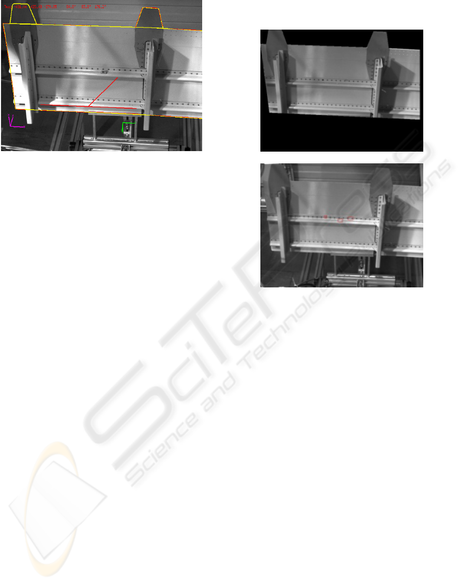
Figure 3: Localization of an object to be inspected and
computation of an initial optimal inspection trajectory.
3 AUTOMATIC DETECTION OF
TEST ZONES
Two approaches can be applied to find automatically
anomalies on a test object. One is model-based
comparison between the CAD-Model projection and
the extracted image features (edges, corners,
surfaces) to detect geometric differences (Veltkamp
and Hagedoorn, 2001). Another one resembles
probabilistic alignment (Pope and Lowe, 2000) to
recognize unfamiliar zones between view-based
object image and test image.
In this second step, we used purely image-based
methods and some ideas of the probabilistic
alignment to achieve a robust inline detection of
anomalies under the assumption that the object view
changes smoothly. The same wide-range camera for
object localization was used for this step.
Using the result of object localization to segment
an object from an image, a database with 2D object
images can be built up in a separate learning step.
We postulated that the views were limited either of
the front side or the back side of the test object with
small changes of viewing angles and furthermore
postulated that we had constant lighting conditions
in the environment.
We used the calibration matrix and the 2D object
images to create a 3D view-based virtual object
model at the 3D location where an actual test object
was detected. The next process was to project the
view-based virtual object model into the image plan.
The interesting test zones (anomalies, see Figure 4)
where detailed inspections were needed (see section
4 and 5) were detected within the segmented image
area by the following steps:
• comparison between the projected view-based
object image and the actual test image;
• morphological operations;
• Feature analysis.
Figure 4: Upper: One of the segmented object images in
the learning step. Only the segmented area in an image is
relevant for the detection of anomalies. Lower: The
automatic detected test zones are marked with red
rectangles (overlays).
4 TIME-OPTIMAL DYNAMICAL
PATH PLANNING
In the third step, an optimized inspection path plan is
generated just in time, which is then carried out
using various inspection-specific short-range sensors
(e.g. cameras, feeler, etc.).
All the interesting test zones or the regions of
interest (ROIs) have been found in the second step,
but the path plan is not perfect yet. A time-optimal
path has to be found from the supervising system.
The problem is closely related to the well known
travelling salesman problem (TSP), which goes back
to the early 1930s
(Lawler et al., 1985; Applegate et
al., 2006). The TSP is a problem in discrete or
combinatorial optimization. It is a prominent
illustration of a class of problems in computational
complexity theory which are classified as NP-hard.
The total number of possible paths is calculated
by: M = (n – 1). The definition of the TS-problem is
based on the following assumptions:
• Modelled as a graph with nodes and edges;
FLEXIBLE ROBOT-BASED INLINE QUALITY MONITORING USING PICTURE-GIVING SENSORS
299
• Graph is complete, this means that from each
point there is a connection to any other point;
• The graph can be symmetric or asymmetric;
• The graph is metric, that means it complies the
triangle inequality C
ij
≤ C
ik
+ C
kj
(e.g. Euclidian metric, maximum metric).
Locking at the algorithms for solving TS-problems,
there exist two different approaches:
Exact algorithms which guarantee a global
optimal solution and heuristics, where the solution
found is only locally optimal.
The most accepted exact algorithms which
guarantee a global optimum are Branch-and-Cut
Method, Brute-Force and Dynamic Programming.
The major disadvantage of the exact algorithms
mentioned above is the time consuming process
finding the optimal solution. The most common
heuristic algorithms used for the DSP are:
• Constructive heuristics: The Nearest-Neighbor-
Heuristic chooses the neighbor with the
shortest distance from the actual point.
The Nearest-Insertion-Heuristic inserts in a
starting path additional points;
• Iterative improvement: Post-Optimization-
methods try to modify the actual sequence in
order to shorten the overall distance (e.g. k-opt
heuristic).
We used a heuristic algorithm with the following
boundary conditions:
• The starting point has the lowest x-coordinate;
• The Nearest-Neighbor-Constructive heuristics
look for the nearest neighbour starting with
the first node and so on;
• The iterative improvement permutes single
nodes or complete sub graphs randomly;
• Terminate, if there was no improvement after n
tries.
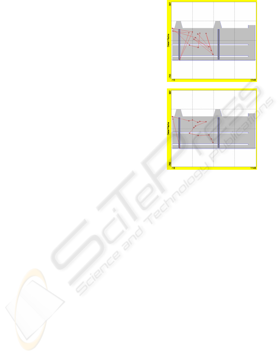
The optimized path planning discussed above was
tested at the DDP with a realistic scenario. Given a
work piece of 1 by 0.5 square meter, the outputs of
the second step (see section 3) are 15 detected ROIs.
This would lead to a total number of about 43.6
billion possible different paths.
Starting with a 1
st
guess as outlined with an
associated path length set to 100 %, after 15 main
iteration loops the path lengths drops down to nearly
50 % of the first one, and no better achievement
could be found (see Figure 5). The calculation time
for the iterated optimal path was less than 1 sec. on a
commercial PC, Intel Pentium 4 with 3 GHz, and
took place while the robot moved to the starting
position of the inspection path.
Figure 5: Upper: initial path; Lower: final path.
5 VISION-BASED INSPECTION
In the fourth step, the robot uses those sensors which
are necessary for a given inspection path plan and
guides them along an optimal motion trajectory into
the previously-identified ROIs for detailed
inspection. In these ROIs a qualitative comparison
of the observed actual topography with the modeled
target topography is made using image-processing
methods. In addition, quantitative scanning and
measurement of selected production parameters can
be carried out.
For the navigation and position control of the
robotic movement with regard to the imprecisely-
guided production object as well as for the
comparison of the observed actual topography with
the target topography, reference models are required.
These models, using suitable wide-range and
short-range sensors, were scanned in a separate
learning step prior to the generation of the
automated inspection path plan. Two sensors have
been used for our work: A 3D split-beam sensor is
used (Deutscher et al., 2003) for the metric test task
(see Figure 6) and a short-range inspection camera
with a circular lighting is used for the logical test
task. For a fuselage, for example, it can be
determined if construction elements are missing
and/or if certain bore diameters are true to size.
ICINCO 2008 - International Conference on Informatics in Control, Automation and Robotics
300
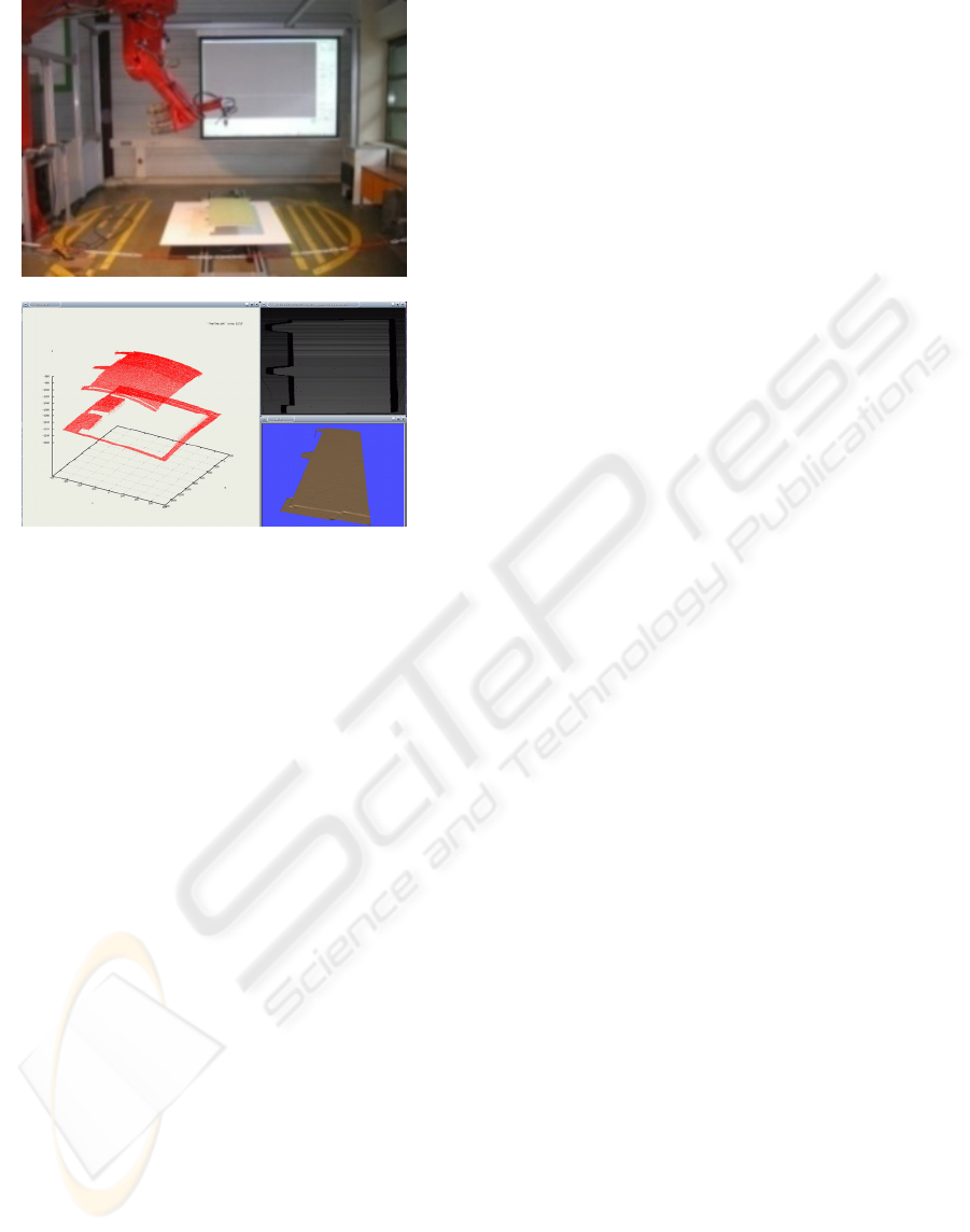
Figure 6: A split-beam technique captures the structure of
a 3D object (upper part) and translates it into a graphic
model (lower part).
By using the proposed, robot-based concepts of
multiple sensor quality monitoring, the customary
use of expensive 3D CAD-models of the test objects
for high-precision CNC controlled machine tools or
coordinate inspection machines becomes, in most
instances, unnecessary.
An intelligent, sensor-based distance-control
concept (Visual-Servoing-Principle) accurately
controls the robot’s movements with regard to the
work piece and prevents possible collisions with
unexpected obstacles.
6 CONCLUSIONS AND FUTURE
WORK
A development and demonstration platform (DDP)
for flexible inline quality monitoring using picture-
giving sensors was created.
The primary goal of the DDP is to investigate,
optimize and demonstrate to potential cooperation
partners how the system can be applied to reduce
effort and to increase flexibility. For example, it can
be used in the robot-based coordination of short- and
wide-range monitoring, for the introduction of
learning-capable evaluation processes, as a tool for
visualizing results and for user interaction, as well as
for the flexible networking and integration of
various wide- and short-range sensors.
Further inspection sensors, which are based on
another measurement principle, will be developed
soon on the sensor magazine and made available for
the surface testing. Investigations and pre-
developments for further (complex) applications can
be realized with the platform at small expenditure.
The applications for example can look like:
• The surface inspection of the outside and the
structural examination of the inside of a car
door;
• The crawler-type vehicle order supervision
within the range of a car window.
ACKNOWLEDGEMENTS
This research was supported by the „Fraunhofer-
Gesellschaft zur angewandten Forschung e.V.“
internal Program.
REFERENCES
Applegate, D. L., Bixby, R. E., Chvátal, V., Cook, W. J.,
(2006). The Traveling Salesman Problem: A
Computational Study. Princeton University Press.
ISBN 978-0-691-12993-8.
Deutscher, R., Munser, R., Hartrumpf M., (2003).
Detection and Measurement of Damages in Sewer
Pipes with a 3D-structured Light Projection Sensor,
In: tm - Technisches Messen 70, 2003(07):338-345.
Lawler, E. L., Lenstra, J. K., Rinnooy Kan, A. H. G.,
Shmoys, D. B., (1985). The Travelling Salesman
Problem. A Guided Tour of Combinatorial
Optimization. Wiley, Chichester 1985. ISBN 0-471-
90413-9.
Müller, Th., (2001). Modellbasierte Lokalisation und
Verfolgung für sichtsystemgestützte Regelungen,
Dissertation an der Universität Karlsruhe (TH), 8.
Februar 2001.
Pope, A. R., Lowe, D. G., (2000). Probabilistic Models of
Appearance for 3D Object Recognition. International
Journal of Computer Vision, 40(2):149–167.
Sung, C.-K., Kuntze, H-B., (2006). Flexible roboter-
basierte Qualitätsüberwachung mit bildgebenden
Sensoren, Sensor Magazin, Magazin Verlag Hightech
Publications KG, Bad Nenndorf, 2006(3):24-26.
Veltkamp, R.C., Hagedoorn, M., (2001). State-of-the-art
in shape matching. In M. Lew (Ed.), Principles of
Visual Information Retrieval, Springer.
FLEXIBLE ROBOT-BASED INLINE QUALITY MONITORING USING PICTURE-GIVING SENSORS
301
