
IMPROVEMENTS IN THE FIELD OF DEVICE INTEGRATION
INTO AUTOMATION SYSTEMS WITH EMBEDDED WEB
INTERFACES
1
Anton Scheibelmasser,
2
Jürgen Menhart
1
Department of Automation Technology, CAMPUS 02, Körblergasse 126, 8021 Graz, Austria
2
Test Bed Automation and Control Systems, AVL List GmbH, Hans List Platz 1, 8020 Graz, Austria
Bernd Eichberger
Department of Electronics, Technical University Graz, Inffeldgasse 12, 8010 Graz, Austria
Keywords: Measurement device, automation system, device integration, embedded web interface, automotive test bed.
Abstract: Web-Technologies which came up in many fields of automation seem to be a solution which improves
device integration in many ways. On the one hand the used Ethernet improves the installation techniques
with reliable and approved network cables and routing devices. On the other hand the used internet
protocols provide several services for the application software development. With the introduction of those
services, the local controller of the measurement devices has to execute complex communication protocols
in addition to the device specific tasks. This fact has serious influences on the measurement device
instrumentation and the execution of the device firmware. Concerning new developments and compatible
adaptations of existing instruments several ways for the integration of web technologies are available. The
following article is intended to explain the architectural aspects of device integrations using Industrial
Ethernet by means of an embedded web server. As a practical example to this architecture, concepts and
results of a new developed communication module called EWI (embedded web interface) are given to
demonstrate the improvements in measurement device integration in the field of automotive test bed
automation.
1 INTRODUCTION
Automation systems like test beds in the automotive
industry are used for the development and the
quality control of combustion engines. In order to
evaluate the interesting quantities, a lot of
measurement devices have to be controlled to
acquire the data during a test run. From the
automation system’s point of view these
measurement devices can be seen as automata
incorporating a finite state machine. Integrating such
devices in an automation system means to
synchronise the states of the measurement device
with the states of the automation system. As those
devices are physically separated from the test bed,
synchronisation has to be performed by means of
communication lines. From this point of view device
integration can be split into software aspects like
device driver development and hardware parts like
network design and installation. Concerning the
network aspect, web technologies have spread over
in many fields of application. As the components
have become cheap and reliable, the well defined
Ethernet (Metcalfe, Boggs, 1976) was introduced in
the field of automation technology. Because of the
standardized bus system, network cables and
components like plugs, transceiver, switches, routers
and gateways, Industrial Ethernet (Hirschmann,
2007) has established in several fields of automation
technology. In many applications it was extended to
real time derivates (Powerlink, 2003) of this
standard. Particulary automation systems in the field
of combustion engine development, called test beds,
are a potential field for the use of Industrial
Ethernet.
94
Scheibelmasser A., Menhart J. and Eichberger B. (2008).
IMPROVEMENTS IN THE FIELD OF DEVICE INTEGRATION INTO AUTOMATION SYSTEMS WITH EMBEDDED WEB INTERFACES.
In Proceedings of the Fifth International Conference on Informatics in Control, Automation and Robotics - ICSO, pages 94-99
DOI: 10.5220/0001479100940099
Copyright
c
SciTePress

As the test bed automation system has to
control a lot of measurement devices, there are high
requirements concerning the communication. A
central task of the system in this context is the
synchronisation of the used measurement devices.
Synchronisation is needed in order to drive the
internal state machine of the devices in the desired
state of the automation system (e.g. measurement).
On a typical test bed the measurement devices are
seperated from the automation system. Therefore
synchronisation is only feasable by means of
communication lines. So measurement device
integration into automation systems can be split up
into two parts.
The first one is the network part. A lot of
measurement devices have to be connected to the
test bed by means of communication lines. Typically
existing test bed measurement devices are connected
by means of peer to peer connections (e.g. RS232).
This causes problems concerning the available
connectors at the automation system and problems
related to the available data acquisition rate. Based
on traditional master/slave communication protocols
and low data rate connections (e.g. 9600 Baud),
timing requirements for high dynamic combustion
engine tests are not met. So improvements in these
directions are required.
The second part of device integration is the
software part. Based on generic device drivers
(Scheibelmasser, Traussnigg, Schindin, Derado,
2004) the protocol layer integration can be managed
generically. Based on a Measurement Device
Description (MDD) a flexible and efficient way for
the device driver development is applicable.
Concerning the appropriate graphical user interface
(GUI) a similar methode is not available. Typically,
a lot of software components have to be developed
for different plattforms to provide the user with the
appropriate visualisation for every measurement
device. This implies high efforts and an economical
disadvantage.Therefore new concepts in terms of
device visualisation are needed. In both parts of
measurement device integration Industrial Ethernet
promises an improvement. In case of network
problems, Industrial Ethernet provides the user with
a high speed bus system. This avoids the connector
problems and the data rate restrictions. Concerning
the software part, the available Ethernet protocols
enables a lot of services (e.g. http, ftp) which are
available for implementing economical and high
quality user interfaces and additional improvements
in the field of service and maintenance.
2 INDUSTRIAL ETHERNET
If we introduce the Ethernet in an automation
system, we provide the user with a lot of new
capabilities. This chapter is intended to summarize
the characteristics of such communication lines.
2.1 Bus Features
In contrast to the traditional peer to peer connections
between the automation system and the
measurement device, a bus system like Ethernet
provides the capability to connect several devices to
one line (network). Additionally, Ethernet increases
the useable bandwidth in high ranges (e.g. GHz).
Therefore existing restrictions concerning the
connectors on the host system or the data rate
acquisition problems could be easily solved. A
possible disadvantage of this solution lies in the fact
that the bus feature implies the need of a bus
arbitration which is responsible for loosing a
deterministic bus response time. Therefore an
extension of the classical standard is necessary if
hard real-time is required. In most cases the user
interfaces require only soft real-time. So the
standard Ethernet protocol is sufficient to support
these applications.
2.2 Network Capability
Based on the standard and the defined network
protocol stack, measurement devices which are
connected to the Ethernet are able to communicate
not only in the local network with the automation
system but worldwide in the web. This feature
enables on the one hand improvements in the area of
remote control, remote maintenance and updating
parameters or software in the field. On the other
hand the security aspects will conquer against these
features and lead to protected small subnets locally
to the automation system. Depending on the required
application the security aspect has to be taken into
consideration and should be adjusted to the needed
level.
2.3 Service Aspects
If we use the Ethernet with the standardized
protocols (e.g. TCP/IP, UDP, HTTP) to connect the
measurement devices, a lot of services are available
to improve the human machine interface. Using
these services, the challenges of the measurement
device visualisation could be improved in many
ways by means of embedded web-server.
IMPROVEMENTS IN THE FIELD OF DEVICE INTEGRATION INTO AUTOMATION SYSTEMS WITH
EMBEDDED WEB INTERFACES
95

Technologies like JAVA or .NET are available to
program the appropriate user interface. The
graphical user interface (GUI) of such a device is
shown within a web-browser window independent
from the computer platform. The respective program
instructions (e.g. JAVA Applet) for the visualisation
and control are stored in this scenario in the
measurement device. In addition to this, user
manuals, service instructions or electronical data
sheets are available inside the device and accessible
by means of Ethernet protocols (e.g. ftp). The
challenge of implementing this method lies in the
appropriate hardware and software design of
measurement device.
3 SYSTEM ARCHITECTURE
In contrast to the traditional measurement device
visualisation, the development of additional PC-
Programs for control and visualisation could be
avoided if we are using the Ethernet technology. As
mentioned, the required human machine interface is
implemented by means of applets which are stored
in the respective device and are executed within a
web browser. The details of the applets and the
methods used for the implementation should not be
part of this work. The main focus of this paper
concerns the communication aspects of an
embedded web server solution. Using the Ethernet
protocols for the measurement device
communication increases the efforts for the
communication task in the device. This fact has two
consequences. Existing devices are not able to carry
out this additional task because of their limited
resources. New device developments have to
introduce additional hardware which is capable to
execute not only the application program but an
operating system with the Ethernet protocol stack. In
addition to the protocol stack, a files system and a
multitasking support are necessary to support the
desired web-services. Concerning the control aspects
of the measurement device, we have to take care not
to loose the real time aspects. From the economical
point of view we have to consider the side effects of
introducing an operation system (e.g. licences) and
the consequences in terms of additional hardware
(e.g. memory). Never the less a compatible solution
for existing measurement devices is required
additionally. A further aspect lies in the fact that the
introduction of a fast bus connection will not
automatically yield to a higher data acquisition rate.
Typically, existing firmware and protocols limit the
performance of the system. So a appropriate
hardware architecture is necessary to support the
demanded improvements.
Based on a principle which was already
implemented in a density meter (Röhrer, 1991) there
exists a trade off concerning the improvement of the
device communication. If we separate the non real-
time tasks like human machine interface from the
real-time control tasks of a system with the
introduction of two independent execution units (e.g.
computers), we can achieve a solution which
provides a lot of advantages. Using this concept, we
can use even existing small and economical
controller solutions without any modifications to
carry out the real time control task. In contrast to
this, improved communication or human machine
interaction is done by an additional device computer
which communicates with the real time controller on
a proprietary and efficient protocol (e.g. SPI). This
architecture provides the system not only with real
time advantages but also with economical benefits.
4 TEST BED INTEGRATION
Based on the above mentioned considerations the
device integration of measurement devices in an
automotive test-bed automation system should be
shown. An additional computer called EWI is
introduced which works as a gateway between the
traditional RS232 lines of the measurement device
and the Ethernet. Based on this component, a new
integration concept was developed.
4.1 EWI Definition
The main part of the integration concept is a
standalone working EWI (embedded web interface).
According to the different aspects of the
measurement devices (e.g. version, protocol,
hardware, technology), this system offers an overall
and compact solution for a new and standardized
integration concept for measurement devices in
automotive automation systems. The EWI was
development on the basis of a few important
concepts:
- An increase of the data communication rate
- A multi user access from the client systems
- Introduction of a new visualisation concept
The EWI offers different solutions for data
communication and exchange and is implemented as
an additional hardware component. Therefore it is
even applicable for existing devices. The highest
priority is set on the communication between the
different users. As shown in Figure 1, it takes care of
ICINCO 2008 - International Conference on Informatics in Control, Automation and Robotics
96
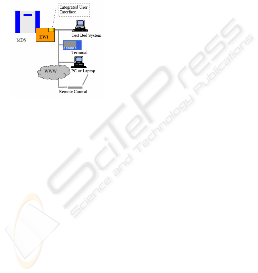
the direct communication between the measurement
devices (MDS) and different client systems (e.g. test
bed system, personal computer, handheld system).
The web interface provides the user on the one hand
with a gateway function (Ethernet to RS232), on the
other hand it offers a data storage for a device
specific user interface (GUI), directly stored in an
extended memory.
Figure 1: EWI integration concept (AVL, 2007).
Depending on the hardware version of the
measurement device, the EWI hardware supports
two integration concepts. The first scenario supports
existing devices and provides the user with an
external component, equipped with a serial
connection to the device and a power supply. In
contrast to this, the EWI-integration in current
measurement devices is done in the system. In this
case the communication will be done directly
between the microcontroller and the EWI using a
high speed serial connection (e.g. SPI). So there is
no need for an additional power-supply.
4.2 Economical Aspects
One of the first steps in the EWI-development was
the consideration of economical aspects. In order to
make a decision, available technologies on the
market were checked against aspects like initial
costs, time to market or training efforts for the
development team. To reach a high reuse of the
module, the EWI should be customized by means of
text-based configuration files. The following
characteristics are configurable:
- Communication protocol definition/settings
- Multi-user access handling
- Automatic device detection
- Boost data handling
Based on this text file and the generic structure the
EWI firmware allows the use of the system even
with different kinds of ASCII based protocols on the
RS232-line. A further economical aspect of the EWI
development was the intention to improve the device
user interface including the visualization. Currently
a lot of different device user interfaces have to be
offered to the customer. Depending on the supplier
of the test bed system, the operating system on the
client, software versions or languages appropriate
software have to be provided. Every component of
such an interface has to be maintained, bug fixed
and released separately. The user has to be trained
on each of the user interfaces because the integration
into the customer’s test bed has to be done always in
a different way. So a main goal was to implement
the user device interface as a web-page inside the
EWI and to use a standard web-browser instead of
proprietary PC-programs.
4.3 EWI Hardware Platform
In consideration of the above mentioned aspects the
OEM-module solution was chosen. The EWI
hardware acts as a communication co-processor
solution. It is implemented as an additional hardware
component and could be used without any influence
on existing controller solution. Therefore it is
applicable even for existing devices in the field.
Concerning initial- and development time and costs,
easy integration of software modules, functionality,
licenses and RTOS features the OEM-module was
the best trade-off. So the EWI was build up on the
IPC@CHIP SC13. The system is based on a 80186
single chip computer and offers a maximum
flexibility and availability for individual
applications. The module incorporates a real time
operating system, RAM, FLASH-Disk, serial and
Ethernet controller and a large number of I/Os. The
EWI software and architecture was built up on the
preinstalled real time operating system. By means of
the generic application software it is now possible to
integrate the EWI in the different measurement
systems, to store and manage the device user
interface and to communicate with the measurement
devices via multiple access.
4.4 Performance Considerations
Members of the automotive industry and their
customers use a common known communication
protocol called AK-Protocol (Arbeitskreis, 1991).
This protocol is based on ASCII and provides an
easy way to communicate with the measurement
IMPROVEMENTS IN THE FIELD OF DEVICE INTEGRATION INTO AUTOMATION SYSTEMS WITH
EMBEDDED WEB INTERFACES
97
devices on the test bed. It has been used for a long
time and is described in user manuals of test bed
devices. The communication is typically done via a
point to point serial line connection in a master/slave
mode. As the test bed devices are typically equipped
with two serial lines, a connection for a maximum of
two users is feasible. The AK protocol offers the
user several commands, to switch the device into
another mode (set), to acquire data (acquire) or setup
new parameters (store) on the system. The
interpretation of the AK protocol for a customer is
very complex and varies between several
measurement devices. To present an easier control
mechanism for the user, the supplier of such a
measurement system includes device user interfaces
on his test bed systems or PCs. These software
components are in communication with the
measurement devices and offer the user a simplified
view of the system. The communication rate
between the participants depends on the client
system. It varies between 1 Hz up to 10 Hz on
current systems in the field. The communication
rate, the operating systems and the software
platforms are totally different. According to these
differences, the standardized EWI integration
concept has to consider the different communication
rates in order o offer an overall solution in terms of
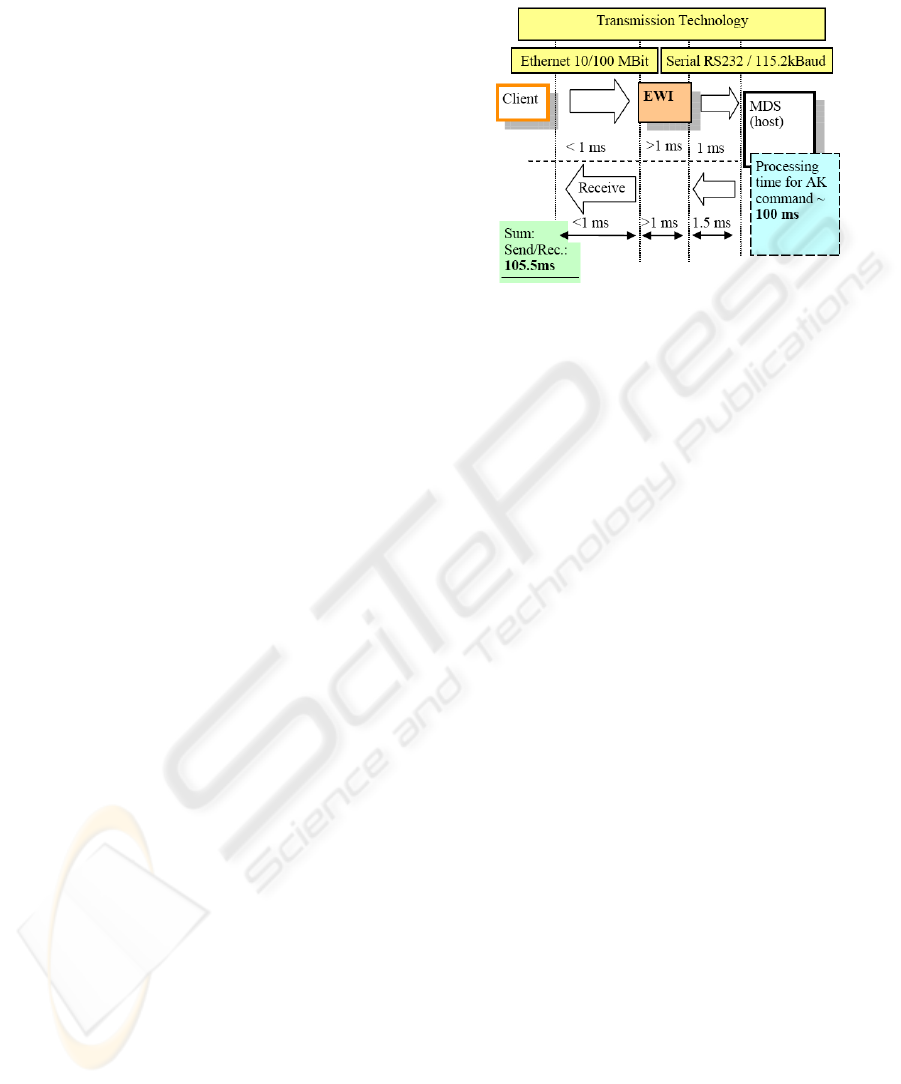
test bed integration. A closer look to the protocol
timing shows that the bottleneck of the
communication can be found in the measurement
devices itself. In current measurement devices the
processing time takes about 100 ms. Due to the used
hardware this time is necessary to receive the serial
line string of the ASCII protocol, to interpret the
frame, to calculate the data and to send it back to the
client on the serial line. In comparison to this time,
the communication of a command on the serial line
between the client and the measurement device takes
about 25 ms. It must be considered that the EWI is
now a third partner in the communication line
between the host and the client, and should not
decrease the data rate between these communication
partners. To improve the communication between
the client and the host system, the EWI concept is
split up into two parts.
The first part is the increase of the
communication data rate between the client and host
system by means of changing the physical layer and
the protocol to Ethernet and TCP/IP.
The second part of the concept increases the
communication data rate between the EWI module
and the measurement device system. Instead of 9600
Baud the communication was increased to a data
rate up to 115.2 kBaud. In this case the elapsed time
can be decreased to 5.5 ms instead of 25 ms (Figure
2). The new communication schema offers now an
overall communication time of about 105.5ms
between the client and the host system.
Figure 2: Transmission rates (Menhart, 2007).
Without changing the existing controller hardware in
the measurement device, no further improvement of
the transmission time is possible. Due to this fact the
data rate for existing devices is limited up to 10Hz.
But a main demand of the integration concept was
the ability to process incoming data from the
measurement device with a data rate of 50 Hz. In
order to achieve this, the communication schema
was extended with a so called Boost mode which
was implemented in parallel to the ASCII based
communication between the host and the client.
4.5 Data Acquisition/Boost Mode
As mentioned, it will be hardly possible to reach a
data rate up to 50 Hz based on an ASCII based AK
protocol without a change directly in the
measurement device. The bottleneck between the
communication structure – client, EWI, host - is the
processing and interpretation time of the AK strings
in the measurement devices itself.
The solution for this problem is a concept
based on a mixed mode of communication. A
transparent standardized ASCII mode and a fast
binary data mode called “boost mode”. To achieve
the requirement of a measurement data rate up to 50
Hz the communication will be done via this boost
data mode in form of binary data sent from the
measurement devices to the EWI. The data
communication will be started and controlled from
the measurement device, independent which client is
in communication. The goal of the solution is to
relieve the device from processing ASCII based AK
data acquisition frames. Therefore the most
important data of the measurement devices – the
measurement data – will be sent to the EWI via
binary data. In case of a client data acquisition the
ICINCO 2008 - International Conference on Informatics in Control, Automation and Robotics
98
data are taken from the EWI and no AK frame to the
device is invoked.
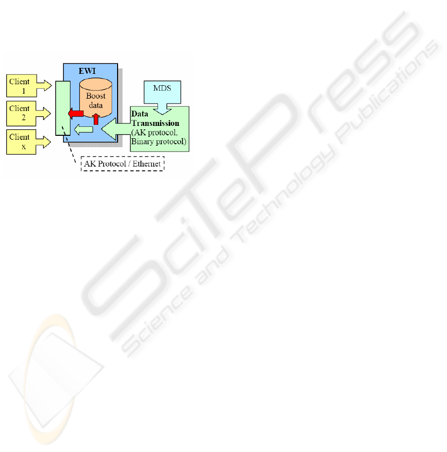
In parallel the standard communication like
parameter settings or service/maintenance
commands will be done via the standard AK
protocol. By means of this concept a dual
communication is established. The processing time
of the measurement device is not influenced and the
client receives the AK data with a transmission rate
up to 50 Hz. Due to the fact that the communication
between the clients and EWI is now done via
Ethernet, a multiple access from the clients to this
boost data and the standard AK commands is
possible. (Figure 3).
Figure 3: Multiple client access via EWI (Menhart, 2007).
5 CONCLUSIONS
In general the embedded web interface (EWI)
represents a uniform and excellent solution for the
integration of measurement devices into automotive
test bed systems. It offers a complete support of the
Ethernet technology as well as a standardized
solution to overcome the problems of existing data
transmission and communication modes. Providing
the user with an Ethernet connection on the
measurement device solves a lot of problems. As the
peer to peer connections of RS232 lines are replaced
with high speed, low cost and high reliable bus
connections, the network problems are sufficiently
solved. The used TCP/IP protocol offers the
application software a lot of services. These services
are able to improve not only the communication rate
but even the user interface by means of embedded
web-server technologies. Implementing such server
in a measurement device enables the devices to
provide their data not in traditional protocol frames
but as web-service on a graphical web-page
accessible with a standard web-browser.
The EWI concept, implemented as a
communication co-processor has shown excellent
results in the field tests. The used EWI principles
and methods are able to establish a standardized way
of measurement device integration into test bed
automation systems.
REFERENCES
AVL List GmbH, 2007, Embedded Web Interface,
Test Bed Instrumentation Systems, www.avl.com
Röhrer, R., 1991. Intelligente Instrumentierung von
Messgeräten, Berichte der Informationstagung ME91,
pp.46-50, Fric-Verlag
Scheibelmasser A., Traussnigg U., Schindin G., Derado I.,
2004, Device Integration into automation systems with
Configurable Device Handler, ICINCO 04
Conference, Setubal
Metcalfe R.,Boggs R., 1976, Ethernet: Distributed
Packet, Switching for Local Computer Networks,
Association for Computing Machinery, Vol19/No5
Hirschmann, 2007, Industrial Ethernet, http://
www.hirschmann-ac.de/Deutsch/industrial-ethernet/
index.phtmlww.hirschmann.com
Menhart J., 2007, Measurement device integration via
Embedded Web Interface, Diploma Thesis
CAMPUS02 University of Applied Sciences, Graz
Arbeitskreis der deutschen Automobilindustrie, 1991,
V24/RS232 Schnittstelle – Grundsätzliches, UA
Schnittstelle und Leitrechner
Powerlink, 2003, Ethernet Powerlink Standardisation Group,
www.ethernet-powerlink.org/
IMPROVEMENTS IN THE FIELD OF DEVICE INTEGRATION INTO AUTOMATION SYSTEMS WITH
EMBEDDED WEB INTERFACES
99
