
A PEN AND PAPER METAPHOR FOR ORCHID MODELING
Glenn McCord, Burkhard W
¨
unsche, Beryl Plimmer, Greg Gilbert and Christian Hirsch
Department of Computer Science, University of Auckland, Private Bag 92019, Auckland, New Zealand
Keywords:
Sketch-based modeling, free-form surfaces, floral modeling, surface deformation.
Abstract:
The creation of 3D computer models is an essential ta sk for many applications in science, engineering and arts
and is frequently performed by untrained users. In many cases speed and simplicity of the modeling process is
more important than matching the geometry of the modeled object exactly. Sketch-based modeling has been
suggested as an important tool for such applications.
In this paper we extend the pen and paper metaphor with a paper sculpting metaphor which is applied to
sketched shapes. Using these techniques we present an efficient and effective tool for orchid modeling. We
discuss the inher ent properties of orchid flowers and use them to develop constraints for representing the
complex surface shapes of orchids with simp le 2D sketches. Surface details are added using noise functions.
Additional surface modifications are possible using the paper sculpting metaphor. By computing inherent
bending axis from the skeleton of a sketched 2D shape the user is able to warp leaf-like structures like if they
were cut from a piece of paper. The intuitive object manipulation of our tool means that an otherwise complex
model can be created by an inexperienced, non-artistic user in a short period of time.
1 INTRODUCTION
The explosive growth of computer simulations and
virtual reality applications has let to an exponential
increase in the demand for computer models. While
initially such models were developed by artists or sci-
entists, it is now common that untrained users want to
create models of everyday items, e.g. for applications
such as ”Second Life”. Traditional modeling tools of-
fer a wide range of powerful algorithms to control the
shape and look of models but often have a steep learn-
ing curve and are non-intuitive which results in long
modeling times, especially for novice users.
One of the difficulties for inexperienced users
is that these tools are not based on any real world
metaphor. Pencil and paper sketching, for example,
is one of the simplest yet effective ways to exercise
some artistry, yet few modeling tools support dig-
ital pens (stylus) to any significant degree. Other
metaphors, such as paper sculpting, can provide an
interaction that makes it easier for users to predict the
results of an action.
This paper presents a tool blending a paper sculp-
ture and sketching metaphor (where sketched lines
represent paper cutouts) for the efficient and effec-
tive modeling of orchid flowers. 2D sketches are used
to define the cross-section, silhouette and bending of
leaf-like shapes and noise functions and various tex-
turing techniques add surface details.
Section 2 reviews previous works in sketch-based
and flower modeling. Section 3 introduces the new
modeling techniques proposed by us and section 4
gives implementation details. Results are shown and
discussed in section 5. We conclude this paper in sec-
tion 6 and suggest issues for future research.
2 RELATED WORK
Our orchid modeler draws on work from three main
areas of research: sketch-based modeling, flower
modeling and surface deformation. A detailed sur-
vey and classification is given in (McCord, 2007). Of
particular interest for our application is Igarishi et al.’s
Teddy application, which creates 3D objects by inflat-
ing 2D sketches based on their width, and provides
tools for cutting and combining them to create more
complex shapes (Igarashia et al., 1999).
A popular way to design plants semi-
automatically are L-systems whereby plant structures
are constructed using rule based logic (Prusinkiewicz
119
McCord G., Wünsche B., Plimmer B., Gilbert G. and Hirsch C. (2008).
A PEN AND PAPER METAPHOR FOR ORCHID MODELING.
In Proceedings of the Third International Conference on Computer Graphics Theory and Applications, pages 119-124
DOI: 10.5220/0001098401190124
Copyright
c
SciTePress

and Lindenmayer, 1990). Related to this is are
p-graphs (prototype graphs) (Lintermann and
Deussen, 1999). The nodes of these directed graphs
reflect the relationship between plant components,
but additionally have attributes encoding shape
parameters.
Such abstract, bottom up approaches can model
the natural growing process, but are non-intuitive and
difficult to control without extensive experience. Ijiri
et. al. have shown that an effective way of creating
realistic flowers is to sketch and edit each individual
flower component (petals, flower head etc), and then
combine them together to form the complete flower
model (Ijiri et al., 2006). In order to make the flower
modeling process more an artistic exercise, it has also
been shown that a user can sketch a plant in its en-
tirety, and then have each of its sketched components
replaced with 3D equivalents (Ijiri et al., 2006).
3 MODELING OF ORCHIDS
3.1 The Anatomy of an Orchid
Orchids differ from most other plants by the complex
structure of their flowers, which generally have three
outer sepals, three inner petals and a single large col-
umn (Fortner, 2007) as illustrated in figure 1:
• Sepals: The glorified remains of the flower bud.
There is usually a dorsal (top) sepal and two lat-
eral sepals.
• Petals: Three petals of which two flank a large and
flamboyant petal called the lip or labellum.
• Column: Unlike other flowers, both the male and
female reproductive organs (stamen and pistil) are
combined into a single column (gynostemium).
• Operculum: The Column is located under the Op-
erculum but is invisible on many orchid species.
For that reason we have ignored this structure so
far in our modeling tool
Orchids are bilaterally symmetrical (left and right half
are symmetrical). The flower will always twist so that
the labellum is pointing downwards (except for those
rare species where the labellum points straight up).
With some orchid species, the lateral sepals fuse to-
gether.
3.2 Modeling Framework
The overall design of our orchid modeler is based on
that by (Ijiri et al., 2005). A complex inflorescence
is designed by constructing each flower component
Figure 1: The prominent parts of an orchid flower.
separately and then combining them to form the final
model. The petals, sepals and stem are constructed
similar to those by Ijiri et al. The labellum requires
specialized techniques explained below. The shapes
can be adjusted using a paper bending metaphor.
The basic building blocks of the modeling process
are the user input strokes, which are a collection of
points converted from screen to world coordinates.
The coordinate transformation is achieved by inter-
secting the lines from the view point to each point
with the canvas plane, which is usually the view plane
(xy-plane). We found that smoothing/filtering of in-
put strokes was unnecessary because they only served
to find the control points for creating bicupic B-spline
surfaces representing the flower components.
3.3 Petals and Sepals
Petals and sepals are geometrically similar and are
constructed using the algorithm explained in the left
image of figure 2. Three strokes define the central
axis and the outline of each of these flower compo-
nents (a). If the strokes don’t meet in one point they
are extrapolated and clipped on the central axis. The
resulting shape is represented by a B-spline surface
(b). The surface can be warped in transverse (c,d) and
longitudinal direction (e,f) using modifier strokes.
The modifier strokes can be placed anywhere
within a sketched shape and define a displacement of
the B-spline surface. The right hand side of figure 2
gives an example. The width modifier stroke defines
the displacement along the cross section where it is
drawn (A) and reduces linearly to zero toward the end
points of the central axis (B). The B-spline surface’s
control points are pulled upwards toward the stroke
(C).
3.4 Labellum
In order to make the modeling of the complex label-
lum surface as easy as possible we define its shape
GRAPP 2008 - International Conference on Computer Graphics Theory and Applications
120
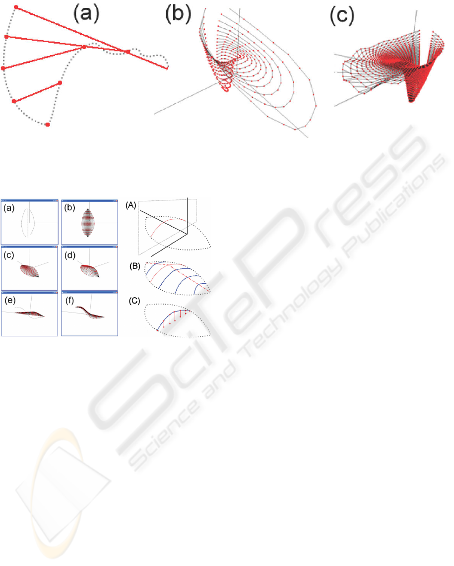
Figure 3: Steps for defining the labellum: The user draws the profile curve of the labellum (a). The stroke is divided at
its lowest point and open ellipsoidal ”isolines” are defined (b). The ”isolines” are sampled and form the control mesh of a
B-spline surface.Trigonomic equations are used to displace the vertices at the lip of the labellum to create a ripple effect (c).
Figure 2: Steps for defining a petal or sepal (left). The shape
modification strokes warp the control curves of the B-Spline
surface (right).
with a single stroke. The surface definition from this
stroke is illustrated in figure 3.
This construction is possible since the labellum is
like an elaborate petal that has been folded and pulled
to form a large lip. This fold means that the label-
lum is not a closed surface and an ordinary bicubic
B-spline surface can be used for its representation.
What is needed, however, is a technique to extend a
2D sketched profile into 3D.
We employ a strategy similar to (Cherlin et al.,
2005). Instead of circles we use open ellipse-like
curves because the fold of the labellum creates an
opening at the back. The sketched profile is divided
into two sections at its lowest point. Both segments
are parameterized and points with the same parame-
ter (connected by solid lines in figure 3 (a)) specify
an ellipsoidal contour. The minor axis of this contour
is proportional to the ratio of the contour’s height and
the total height of the labellum. The maximum diam-
eter is equal to the labellum height.
The contours are then sampled to yield the con-
trol points for the final B-spline surface. Because
the largest distortions occur at the lip of the labellum
more sample points are used in this region.
One of the most interesting features of the label-
lum is its ripply surface. We simulate this effect by
displacing the vertices of the polygonized B-spline
surface with a trigonometric noise function. The rip-
ples of the labellum tend to get larger closer toward
the lip so we add two sine waves together. We found
that a B-spline surface with 30x30 vertices can be dis-
torted with a sine wave with 10 periods before the
ripples start to look like zig zags. The resulting rip-
ple equation defining the offset ρ(s, t) of the B-spline
surface is:
ρ(s, t) = (s ∗ h
max
) ∗ sin(n ∗ (2πt)) ∗ sin(0.5 ∗ (2πt))
where h
max
is the maximum height of the ripples, n
is the number of ripples and t, s ∈ [0, 1] are the para-
meters of the B-spline surface along the labellum lip’s
contour and transverse to it, respectively.
3.5 Shape Deformation
3.5.1 Paper Metaphor
Paper is thin, which makes it an ideal metaphor for 3D
modeling of objects that consist of thin surfaces such
as flowers. In our approach a sketch is interpreted as
a paper cut out that gets sculpted by folding, crimping
and indenting it.
Paper is a widely used artistic medium, not just
because of its prevalence but also because of its flex-
ibility as a modeling medium. One of the most well
known paper crafts is origami, but there is more to
paper sculpting than just folding hard edges. Paper
can be cut, torn, creased, coiled/rolled, cut to form
A PEN AND PAPER METAPHOR FOR ORCHID MODELING
121
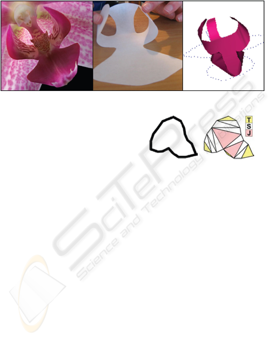
Figure 4: The curvature of a real orchid petal (left) represented with paper (middle) and a digital model that uses paper folding
properties (right).
textured patterns by utilizing light sources, joined to-
gether using tabbing, layered in relief, and textured
by impressing a pattern (Jackson, 1996). All of these
can serve as a modeling metaphors.
The primary paper sculpting techniques are the
ability to cut, curve and crease paper and we have
explored how this metaphor can be used for manipu-
lating surfaces on the computer. Besides the inherent
difficulties with managing 3D objects in a 2D space,
there is also the problem of working with a single
mouse cursor. We are essentially paper sculpting with
one hand.
By blending the sketching and paper sculpture
metaphors together, simple interaction is achieved.
The initial sketch defining the outline of a shape is in-
terpreted as a paper cut out. In order to enable ”fold-
ing with one hand” we automatically compute possi-
ble fold lines. The user selects part of the cut out with
the mouse cursor and drags/pulls at it. As a result,
the selected subpart will fold about an axis formed
depending on the geometry of the cut out.
3.5.2 Folding Axes
Marr and Nishihara noted that the concave parts of a
silhouette define the subparts of an object (Marr and
Nishihara, 1978). User studies where we asked stu-
dents to draw orchid flowers confirmed that the con-
cave parts of such drawings usually denote foldable
regions. The axes about which they fold is defined by
the path that joins one concave curve to the other.
Foldable subparts and folding axes are identified
by sampling a closed sketch curve and applying a De-
launay triangulating. Triangles are defined as either a
terminal, sleeve or junction triangle where each trian-
gle type has either one, two or no shared edges to the
silhouette, respectively (see figure 5). In the Teddy al-
gorithm the mid points of interior edges and the center
Figure 5: The triangulation strategy used by ”Teddy” de-
fines different triangles as Terminal, Sleeve or Junction de-
pending on how many sides are shared with the silhouette.
points of junction triangles are connected to a skele-
ton, which is used as an axis of rotation for generating
3D shapes (Igarashia et al., 1999).
We observed that the edges of junction triangles
isolate the subparts of the sketched shape and hence
define candidate folding axes. Some of the subparts
are very small and only represent local surface de-
tails. We use the pruning method used in ”Teddy”
to eliminate them. The final folding axes are chosen
by traversing the shape contour and selecting the axes
which separate the subparts best. The implementa-
tion also deals with complications which can occur
for more complex shapes (McCord, 2007).
3.5.3 Folding
The bending of the shape around a folding axis is
achieved by rotating each vertex by an angle propor-
tional to its distance from the fold axis. Figure 4 il-
lustrates that the results look similar to those when
bending a flexible piece of paper.
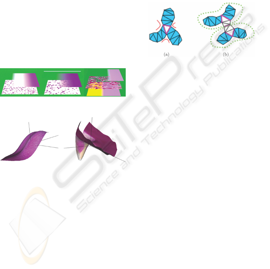
3.6 Orchid Textures
To make the orchids look more realistic both bitmap
texturing and procedural texturing was employed. In
GRAPP 2008 - International Conference on Computer Graphics Theory and Applications
122
order to map bitmaps onto the different parts of the
orchids we decided to obtain images from photos of
real orchids. First we selected a set of orchid photos
which represented a reasonable range of different or-
chid types and textures. For each orchid part (petal,
sepal and labellum) a separate texture needed to be
extracted from these photos.
For some orchid types we used additionally bump
map textures, which were obtained by reducing the
bitmap textures to gray scale values and changing the
intensity and contrast.
Procedural textures were created using the PoV-
Ray description language. By combining different
texture layers we tried to imitate complex pattern ob-
served at real orchids. We used different procedural
textures such as noise textures (for creating spot like
pattern) and simple color gradients. By combining
multiple layers and transparencies realistic results can
be achieved as illustrated in figures 6 and 7
Figure 6: Layers of procedural textures used for an orchid.
Figure 7: The textured petal/sepal and labellum.
4 IMPLEMENTATION
Our implementation was written in C/C++ and uses
the OpenGL and GLUT libraries with SDL being
used to load textures. OpenGL is used for rendering
during interactive modeling and higher quality ren-
dering results are obtained with the Persistence of Vi-
sion Raytracer (POV-Ray) (pov, 2007).
5 RESULTS
Using our tool users were able to create a wide vari-
ety of orchids in a short time as illustrated in figure 8.
Most problems reported by inexperienced users were
related to implementation issues, e.g. that the strokes
defining petals and sepals must be drawn in a particu-
lar order and that currently it is not possible to correct
strokes by scribbling over them.
Another drawback is that the creation of new tex-
tures is a time consuming process requiring some
artistic skills for the procedural textures. Ideally we
would like to have a tool which can extract bitmap
and procedural textures from photographs.
Figure 9: (a) A junction triangle (purple) that stretches
between concave sections (red), identifying the subparts
(blue). (b) For more complex surfaces a fold axis between
two junction triangles is identified as the shortest distance
across the surface. The green dashed lines represent encap-
sulating subparts.
Initial tests indicate that the paper sculpture
metaphor facilitates the task of creating and manip-
ulating the flat surfaces required by 3D flower mod-
els. The interaction becomes less clear when the
user wishes to fold a large subpart that encapsulates
smaller subparts (figure 9 (b)). Currently we only
fold the smallest subpart containing the surface point
clicked by the user. Alternative implementations are
to determine the folding area using a proximity mea-
sure or to fold the larger encapsulating subpart once
the smaller subpart has been folded beyond a critical
angle.
Real orchid petals can have a curvature that is
very difficult to sculpt with paper unless one was to
collapse the paper by crumpling it or using multiple
tiny zigzag-like folds. Modeling such orchid surfaces
would therefore break the paper sculpting metaphor
because simple paper folds maintain surface area.
6 CONCLUSIONS
We have introduced cross-section sketches and noise-
based perturbations as a technique for efficiently de-
signing complex rotation-symmetric or nearly rota-
tion symmetric objects.
A paper sculpting metaphor allows users to fur-
ther modify shapes by bending them around ”natural
A PEN AND PAPER METAPHOR FOR ORCHID MODELING
123
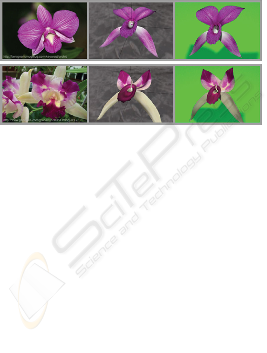
Figure 8: A comparison of real orchid flowers (left) and models constructed with our tool and rendered with OpenGL (middle)
and PovRay (right).
rotation axes” identified from the skeleton and Delau-
nay triangulation of a shape. The proposed interface
eases the transition from the initial conceptual design
into the final 3D model.
Using our modeling tool we found that even un-
trained users can design complex and attractive orchid
flowers in a short time. Various texturing techniques
are used to give the modeled flowers a more realistic
look.
More work is needed to make the user interface
more intuitive and robust toward unexpected user in-
put. Also we would like to extend the number of sup-
ported anatomical parts of an orchid in order to cater
for more orchid features. As mentioned previously
the texture generation must be automated and the tex-
turing capabilities should be extended such that no
two orchids will ever look identical.
REFERENCES
(2007). POV-Ray homepage. URL: http://www.povray.org
[Last accessed 01/10/2007].
Cherlin, J. J., Samavati, F., Sousa, M. C., , and Jorge, J. A.
(2005). Sketch-based modeling with few strokes. In
Proceedings of the 21st spring conference on Com-
puter graphics non-photorealistic animation and ren-
dering (SCCG 05), pages 137–145. ACM Press.
Fortner, L. (2007). Anatomy of an orchid flower. URL:
http://www.orchidlady.com/pages/encyclopedia/orchid
flower anatomy.html [Last accessed 01/10/2007].
Igarashia, T., Matsuoka, S., and Tanaka, H. (1999). Teddy:
a sketching interface for 3d freeform design. In Pro-
ceedings of SIGGRAPH ’99, pages 409–416. ACM
Press.
Ijiri, T., Owad, S., Okabe, M., and Igarashi, T. (2005).
Floral diagrams and inflorescences: interactive flower
modeling using botanical structural constraints. In
Proceedings of SIGGRAPH ’05, pages 720–726.
ACM Press.
Ijiri, T., Owada, S., and Igarashi, T. (2006). Seamless inte-
gration of initial sketching and subsequent detail edit-
ing in flower modeling. In Proceedings of Eurograph-
ics 2006, pages 617–624. ACM Press.
Jackson, P. (1996). The Art and Craft of Paper Sculpture.
Apple Press, Quarto Publishing Plc.
Lintermann, B. and Deussen, O. (1999). Interactive model-
ing of plants. IEEE Computer Graphics and Applica-
tions, 19(1):56–65.
Marr, D. and Nishihara, H. K. (1978). Representation
and recognition of the spatial organization of three-
dimensional images. In Proceedings of the Royal So-
ciety of London, Series B, volume 200, pages 269–
294.
McCord, G. (2007). Surface manipulation using a paper
sculpture metaphor. BSc Honours Dissertation, Dept.
of Computer Science, University of Auckland, Auck-
land, New Zealand. URL: http://www.cs.auckland.
ac.nz/˜burkhard/Reports/2007 S1 GlenMcCord.pdf.
Prusinkiewicz, P. and Lindenmayer, A. (1990). The algo-
rithmic beauty of plants. Springer-Verlag, New York.
GRAPP 2008 - International Conference on Computer Graphics Theory and Applications
124
