RAY-TRACED COLLISION DETECTION FOR DEFORMABLE
BODIES
1
Everton Hermann,
2
Franc¸ois Faure and
1
Bruno Raffin
1
INRIA,
2
Grenoble Universities, France
Keywords:
Collision Detection, Collision Reponse, Physically Based Animation, Deformable Bodies.
Abstract:
This paper presents a new approach to collision detection and modeling between deformable volumetric bod-
ies. It allows deep intersections while alleviating the difficulties of distance field update. A ray is shot from
each surface vertex in the direction of the inward normal. A collision is detected when the first intersection be-
longs to an inward surface triangle of another body. A contact force between the vertex and the matching point
is then created. Experiments show that this approach is fast and more robust than traditional proximity-based
collisions.
1 INTRODUCTION
Collision detection and response is one of the major
computational tasks in physically based animation. It
has thus received considerable attention, and the con-
tributions are too numerous to discuss all of them.
While special shapes such as spheres or cubes allow
the use of optimized methods, the general case of tri-
angular meshes is much more complex. In the case
of rigid objects, the most efficient approaches rely
on signed distance fields. Each point of one object
(which we call the colliding object) is tested against
the distance field of the other (called the collided ob-
ject). If the point is inside the collided object, the
nearest point on the collided surface is found and a
constraint between these points is created. The test
can also be performed the other way round, by switch-
ing the colliding and collided objects. Computing a
distance field is a compute-intensive task that is per-
formed once at initialization time for rigid objects,
and defined with respect to a local reference frame.
When the objects are deformable, the distance
field would have to be recomputed at each time step,
making it too complex for real-time applications. The
most popular strategy is thus to detect pairs of geo-
metric primitives in close proximity, and to set up
constraints to keep them apart. In this approach, the
contact points are those having a distance to a geomet-
ric primitive of the collided below a given arbitrary
proximity threshold. However, discrete time integra-
tion may allow the surfaces to cross each other, and
when a primitive of the colliding object goes deeper
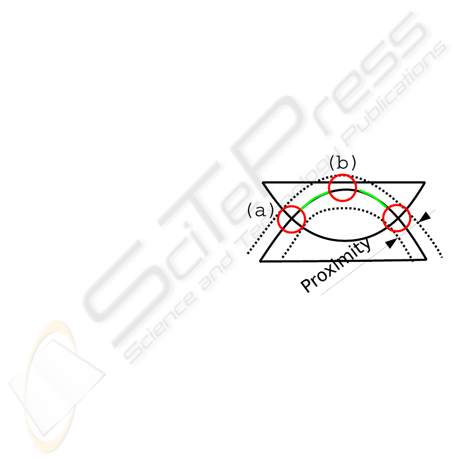
Figure 1: Problems with proximity-based collision detec-
tion when the bodies intersect each other. (a): proximi-
ties inside and outside the intersection volume may balance
each other, resulting in a null net reaction. (b): undesirable
contacts may be modeled. Green: large areas of the inter-
secting surface are ignored.
in the collided object than the proximity threshold, it
can not be identified as a contact point. This results
in poor collision responses that sometimes leave the
bodies in intersection, as illustrated in figure 1.
The problem of surface crossing due to discrete
time integration can somehow be alleviated using so-
phisticated strategies based on collision prediction,
givencurrent positions and velocities. However, these
methods are complex. Their convergence is unclear
and they may require short time steps, while large
time steps are preferable for real-time applications.
293
Hermann E., Faure F. and Raffin B. (2008).
RAY-TRACED COLLISION DETECTION FOR DEFORMABLE BODIES.
In Proceedings of the Third International Conference on Computer Graphics Theory and Applications, pages 293-299
DOI: 10.5220/0001097902930299
Copyright
c
SciTePress
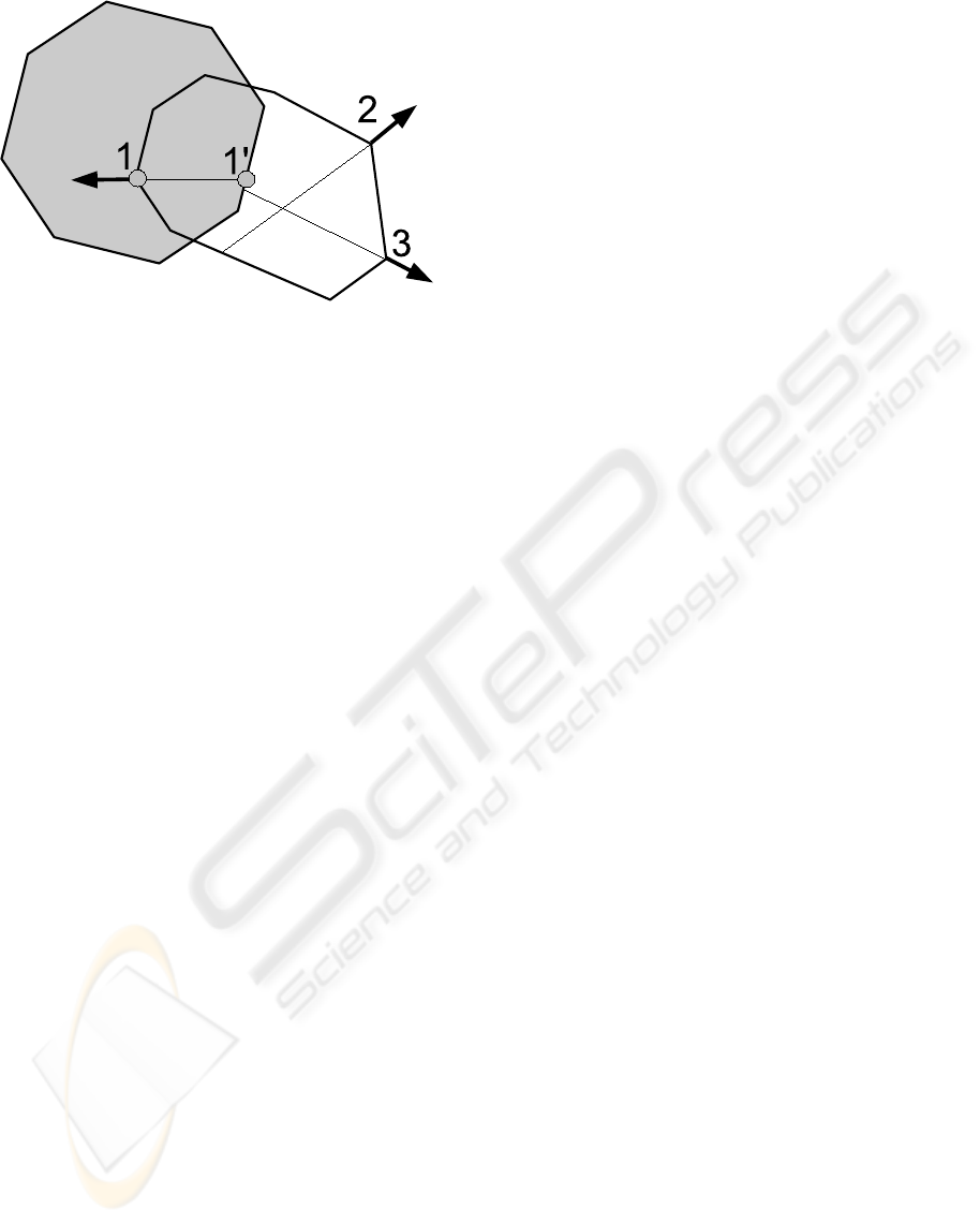
Figure 2: Our ray-traced collision detection. A contact is
modeled at points 1 and 1’ because the ray shot from point 1
on the colliding object hits the inward surface of the collided
object, contrary to points 2 and 3.
Consequently, they have been mainly applied to off-
line cloth simulations.
For volumetric objects, a reasonable amount of
intersection can be visually acceptable, and a robust
contact modeling method would allow us to perform
large time steps. GPU-based methods can detect the
pixels of a colliding surface inside a collided body,
but they do not compute the matching points on the
collided surface. This prevents a robust setting of the
associated contact constraints.
In this paper, we propose to search the match-
ing point along the inward normal of each colliding
point, using a ray-tracing technique illustrated in fig-
ure 2. This approach is simpler than finding the clos-
est primitive, because we search the matching point
on a one-dimensional ray, rather than over the whole
3D space. We then apply penalty forces between the
matching points. Such forces are necessarily perpen-
dicular to the colliding surface, which ensures a rea-
sonable reaction.
The remainder of this paper is organized as fol-
lows. We briefly summarize related work in section 2.
We present our octree-based raytracing in section 3.
Reaction forces are evaluated in section 4, and results
are discussed in section 5.
2 RELATED WORK
The field of collision detection is too large to be re-
viewed in detail here. An excellent survey of colli-
sion detection between deformable objects is given
in (Teschner et al., 2005). Bounding volume hierar-
chies are typically used to accelerate proximity de-
tection (Mezger et al., 2003). Continuous collision
detection can be used to avoid intersections in cloth
simulation (Bridson et al., 2002). Strangely enough,
volumetric elastic bodies have not received much at-
tention. (Guy and Debunne, 2004) apply stochastic
proximity-based surface detection, while (Teschner
et al., 2003) apply spatial hashing to tetrahedra and
apply heuristics to set up contact forces between these
elementary volumes. Distance fields (Frisken et al.,
2000) are generally used when at least one of the
colliding objects is rigid. Their update requires a
volumetric mesh and is reduced to small deforma-
tions (Fisher and Lin, 2001). Image-space techniques
can detect intersections (Heidelberger et al., 2004),
but they can only model reactions along the camera
axis.
3 DETECTION
If we consider a collision pipeline, our algorithm is
placed on the Narrow Phase process, as it works with
pairs of objects that are potentially colliding. It re-
quires a previous step, the Broad Phase, for identify-
ing pairs of objects whose bounding boxes are collid-
ing. Given such a pair of objects, our algorithm finds
pairs of colliding points (one point per object). Col-
lision response forces are then applied to these point
pairs.
To identify these pairs of colliding points, we take
a vertex on an object surface and follow the oppo-
site direction of the normal up to finding a point in
the other object. Our approach allows to solve col-
lisions even if objects are deeply interpenetrated and
triangles are not close enough to be detected based on
proximity. Also, using the normal give us a good di-
rection to be used with collision reaction penalties, so
in the same algorithm we can do the collision detec-
tion and the collision reaction.
Once two objects are interpenetrated and colliding
points are detected, the collision reaction forces are
applied to separate them. Our method does not de-
pend on precomputed data to determine the colliding
points. For this reason, it is well suited to deformable
objects, where the distance fields are too expensive to
be recomputed at each time step.
The search path from one vertex of an object to
one point on the other object can be represented as a
ray with the origin at the vertices and a direction op-
posite to the normal at the vertices. To speedup the
searching of elements that cross this ray, we stored
all the triangles of each colliding objects in an oc-
tree. Therefore we can easily navigate inside this oc-
tree and efficiently find the points crossing the ray.
The octree structure allow us to have a satisfying per-
formance independently from the size of the triangles
used, what is not the case for a regular grid.
GRAPP 2008 - International Conference on Computer Graphics Theory and Applications
294
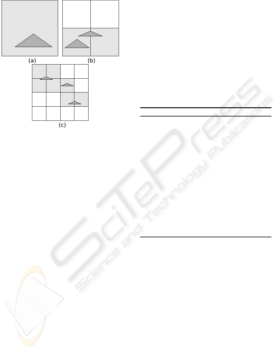
Figure 3: Quadtree version of the proposed triangle distrib-
ution algorithm. (a): a large triangle placed at the first cell
level, (b) 2 triangles stored at the second level and (c) 3 tri-
angles at the third level.
In the next sections we detail how this octree is
built, and how we use this structure to find pairs of
colliding points between two objects.
3.1 Octree Construction
For each potentially colliding object we create an oc-
tree containing the object triangles. We obtain a spa-
tial data structure that allows us to easily find the tri-
angles that intersect a given region. The efficiency of
the octree depends on the triangle spacial distribution.
One way to construct the octree is to split a cell while
it contains more than one triangle. However this ap-
proach does not enable to control the number of cells
a triangle belongs to.
Our algorithm ensures that each triangle is present
in at most eight octree nodes. The goal is to avoid
storing a triangle into a large number of octree cells.
It ensures a good balance between octree precision
and the number of cells to be tested when traversing
the octree. To reach that goal, a triangle is stored at
the deepest level where cell size is greater than the
largest dimension of the triangle’s bounding box (see
Figure 3). Some triangles can be stored into non leaf
nodes, as triangles of different size can be located in
the same area.
3.2 Ray Tracing
We ray-trace starting only from vertices located in the
intersection of the object bounding boxes, which al-
lows us to cull out numerous tests. Our algorithm is
decomposed in two phases (see Algorithm 1): search
for colliding pairs, and result filtering.
The search phase consists in taking the opposite of
the point normal, and following this direction to find
a point on the other object. The octree cells are vis-
ited using the octree traversal algorithm presented by
(Revelles et al., 2000). Each cell of the octree con-
tains a list of triangles that intersect this cell. When
a cell is visited, all the triangles it contains are tested
against the ray using the algorithm from (M
˜
Aller and
Trumbore, 1997). If an intersection point is found,
this algorithm gives us its coordinates and the distance
from the ray’s origin.
Algorithm 1 Collision detection Algorithm.
Require: Object1, Object2
Ensure: pairs of colliding points between Object1
and Object2
for each point1 in Object1 do
point2=traceRay(point1, - point1.normal, Ob-
ject2)
if angle between point1.normal and
point2.normal ≤ π/2 then
continue with the next point
end if
point3=traceRay(point1, - point1.normal, Ob-
ject1)
if distance(point1,point2) ≤ dis-
tance(point1,point3) then
add collision pair to the collision response
end if
end for
Having a pair of colliding points, one on each ob-
ject, we test the validity of the resulting contacts as
illustrated in Figure 4. The first verification concerns
the angle between the normals of both points. An
acute angle means that the ray is entering the sec-
ond object instead of exiting. Eliminating acute an-
gles avoids the misdetection of collision pairs like the
one shown in Figure 4(a), where two differentrays are
traced from O1, but only one is valid, as the angle A
is acute. Applying forces to those points would make
the objects collide even more.
However, only eliminating colliding pairs that tra-
verse the second object from the outside face is not
enough. We must ensure that the point we found is
not outside O1, as only using the normal as filter cri-
terion may generate ambiguous results. A point that
is part of two triangles can have a normal that satisfies
the first criterion even if the point is outside the col-
liding object. Figure 4(b) illustrates the second vali-
dation condition of a colliding point. The ray used to
RAY-TRACED COLLISION DETECTION FOR DEFORMABLE BODIES
295
search a colliding point on O2 is reused to intersect
the object O1. If the point found on O1 (point3) is
closer to the origin of the ray (point1) than the point
on O2, this collision pair is eliminated as the second
point is outside object1. The collision pairs that sat-
isfy all the tests are kept to be treated by the collision
response phase.
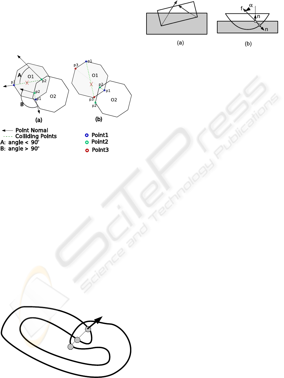
Figure 4: Colliding points validation. Point1, point2 and
point3 denote the points identified by the Algorithm 1.
3.3 Self-collision
Self-collision can be detected using an extension of
our method illustrated in Figure 5. A self-collision is
detected when the ray hits twice the inward surface
of the object. This test is more expensive because all
the vertices of a potentially self-intersecting body are
tested.
4 REACTION
Once collisions are detected and modeled, we apply
a penalty force to each pair of matching points. The
Figure 5: Self-collision detection.
Figure 6: Contact force. In (a), a sharp object undergoes
a non-null net tangential force. In (b), angle α is used to
estimate the quality of the contact model and to weight its
force.
force is proportional to the distance, and parallel to
the line joining the matching points. This guarantees
that Newton’s third law on opposite forces is satisfied.
We apply the force directly to the colliding point, and
we distribute the opposite force to the vertices of the
associated triangle in the collided object according to
the barycentric coordinates of the intersection point.
We perform an implicit time integration to avoid in-
stabilities due to high contact forces.
The direction of the force is not necessarily paral-
lel to the normal of the collided object, as illustrated
in Figure 6, and some contact pairs are more reliable
than others. As a result, sharp objects may undergo
undesirable net tangential forces.
We therefore multiply the intensity of the force by
the cosine of the angle α in figure 6(b). This reduces
the influence of the less reliable contact forces.
To evaluate the contact forces created by our algo-
rithm, we used a cylinder crossed by a plane, and the
expected direction for the resulting force is a vertical
force as shown in 2D in Figure 7. Due to symmetry,
tangential forces should balance each other and the
net tangential force should be null. However, due to
surface discretization, as the rotational position of the
cylinder changes, the resulting force direction may
differ from the normal of the plane.
To measure the variation of the resulting force, we
tested cylinders with a number of sides ranging from
10 to 150. For each cylinder we took 100 different ro-
tational positions, and measured the response forces.
In Figure 8 we show the mean of the variations for a
varying numbers of sides. We observe that the quality
of the resulting force increases with the object level
of detail. For a cylinder having only 10 sides, we
get a worst case deviation of 8%. As we increase
the number of sides, variation levels decrease to about
1%. This variation depends of course on the shape of
the object, and the results improve with smoother ob-
jects. As our algorithm uses penalties to separate the
objects, the usage of the normal direction fits to our
needs, as it give us a good aproximation on the di-
rection one object interpenetrated the other. In some
GRAPP 2008 - International Conference on Computer Graphics Theory and Applications
296
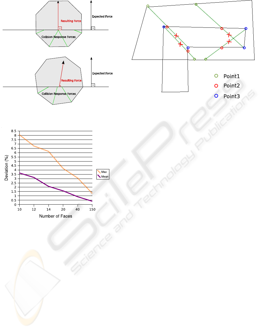
Figure 7: A cylinder undergoing various tangential forces
due to low geometric resolution.
Figure 8: Ratio of tangential and normal force, against the
number of cylinder faces.
cases we are not able to fully separate to objects in
one step, in those situations using the velocity direc-
tion has no meaning, as it was changed by the penal-
ties forces in the previous step.
A limitation of our methods occurs when all the
inward rays cross the colliding body before the col-
lided one, as illustrated in figure 9. In this case, no
collision is detected and the contact force is null. Note
that this does not induce instabilities. A proximity-
based method would succeed if the colliding vertices
were not deeper than the proximity threshold, and
fail otherwise. The same happens when one object
is completly inside the other, and our algorithm does
not find a way to separate them.
Another limitation occurs when an object that is
in a self-colliding state, also collides another object.
In this case, some collision may be missed as the first
colliding point may be an outside face. Also edge-
Figure 9: Our method can fail in case of non-convex inter-
section volume.
edge interpenetration are not always detected as we
project the rays from the object vertexes.
5 RESULTS
We compared the efficiency of our method with a hi-
erarchical implementation of a proximity-based ap-
proach, similar to the one proposed by (Bridson
et al., 2002). The algorithms were implemented
using de Simulation Open Framework Architecture
(SOFA) (Allard et al., 2007). The parallel version of
our algorithm was developed using KAAPI (Gautier
et al., 2007).
The first test consists in starting the simulation
with interpenetrating objects. We observe how the al-
gorithms manage to push the objects apart. In Fig-
ure 10 we have the starting scene followed by the re-
action produced by each algorithm. The ray-tracing
algorithm manages to separate the objects while the
objects are only deformed and stay interpenetrated
with the proximity-based approach. The ray-tracing
applies all the penalties in a direction that separates
the objects. The proximity-based algorithm tries just
to push apart triangles that are too close. As a result,
some penalties are oriented in a direction opposite to
the one that should be used to separate the objects.
Another advantage of our approach is the larger
simulation step (dt) that can be used. With a large
dt objects can move from a non colliding state to a
deep interpenetration. With a proximity-based ap-
proach, deeply interpenetrated objects lead to trian-
gles too far apart to be detected as colliding. Still us-
ing the same scene (Figure 11), the proximity-based
algorithm gives satisfying results up to a maximum dt
RAY-TRACED COLLISION DETECTION FOR DEFORMABLE BODIES
297
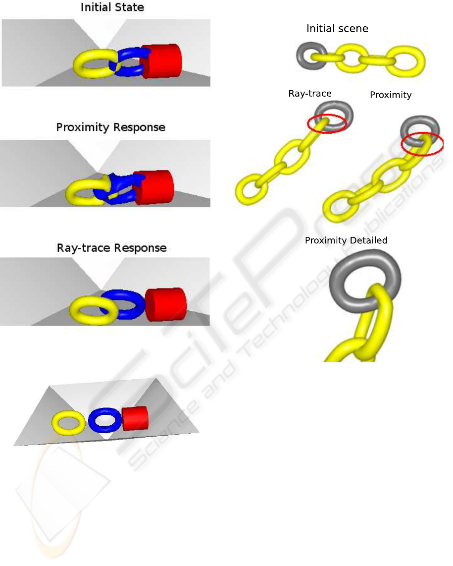
Figure 10: A test scene. Each torus includes 1600 triangles.
Figure 11: Scene used for performance comparison.
of 0.2 seconds, while our algorithm is still effective
up to 0.45 seconds.
In the scene illustrated in Figure 12 we have a sim-
ilar situation where the interpenetration of objects re-
strains the movements when using a proximity-based
approach. The rings start the scene with no collision
between them, but when they get interpenetrated they
are not able to follow the chain movement. How-
ever, with the ray trace algorithm the rings can move
freely, even with interpenetrations. It allow us tu use
larger timesteps without degrading the collision reac-
tion quality.
Figure 12: A deformable chain test.
When running both algorithms one a a Xeon
2.5Ghz machine simulating a scene like the one in
Figure 11, our algorithm reaches 30 fps, while the
proximity-base algorithm reaches only 12 fps. It is
mainly due to a smaller number of colliding points de-
tected by the ray tracing, as close triangles that are not
in a colliding state do not generate colliding points.
With less penalties applied, the solver run faster. The
use of the octree structure to detect matching triangles
also leads to significant performance gains.
In terms of scalability our algorithm behaves as
expected, having a linear degradation of performance
as the number of colliding objects increases. The ba-
sic element of our collision detection algorithm is the
triangle. The algorithm performance depends directly
on the number of triangles needing to be evaluated. In
Figure 13, we display the time to solve 200 iterations
with a varying number of objects in the scene. The
objects used are torus initially interpenetrating each
other as shown in the attached video.
GRAPP 2008 - International Conference on Computer Graphics Theory and Applications
298
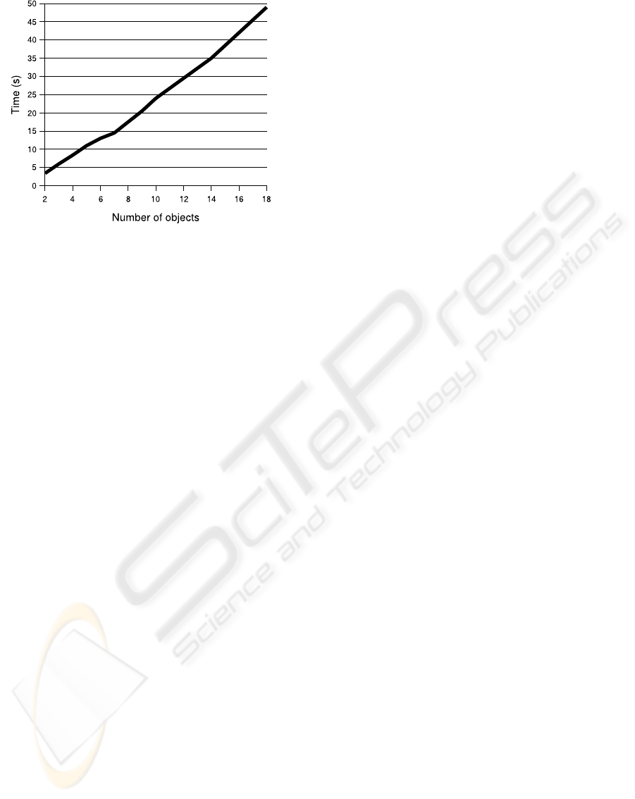
Figure 13: Performance evaluation with a variable number
of colliding torus, each of them including 1600 triangles.
To take advantage of the available multi-core ar-
chitecture, we developed a first simple parallel ver-
sion of the algorithm. Pairs of colliding objects can
be computed independently. We take advantage of
this parallelism inherent to our algorithm to distrib-
ute the pairs to the different processing cores using
a work-stealing load balancing strategy. On a quad-
core processor, the simulation runs more than twice
faster compared to a single core execution. The per-
formance gain is limited by the remaining computa-
tions that are sequential.
6 CONCLUSIONS
We have shown that our novel collision detection and
modeling approach is an interesting alternative to tra-
ditional proximity-based methods, especially in the
case of smooth deformable volumetric objects. The
computation times are shorter, and the robustness al-
lows us to apply larger time steps. The time spent by
constructing an octree is compensated by the acceler-
ation obtained on the ray tracing phase.
In future work, we plan to scale the contact force
at each colliding vertex by the surface area associ-
ated with this vertex, to obtain a more resolution-
independent reaction force. We will also investigate
how to cull out more tests in self-intersection detec-
tion.
REFERENCES
Allard, J., Cotin, S., Faure, F., Bensoussan, P.-J., Poyer,
F., Duriez, C., Delingette, H., and Grisoni, L. (2007).
Sofa an open source framework for medical simula-
tion. In Medicine Meets Virtual Reality (MMVR’15),
Long Beach, USA.
Bridson, R., Fedkiw, R., and Anderson, J. (2002). Robust
treatment of collisions, contact and friction for cloth
animation.
Fisher, S. and Lin, M. C. (2001). Deformed distance fields
for simulation of non-penetrating flexible bodies. In
Proceedings of the Eurographic workshop on Com-
puter animation and simulation, pages 99–111, New
York, NY, USA. Springer-Verlag New York, Inc.
Frisken, S. F., Perry, R. N., Rockwood, A. P., and Jones,
T. R. (2000). Adaptively sampled distance fields: A
general representation of shape for computer graph-
ics. In Akeley, K., editor, Siggraph 2000, Computer
Graphics Proceedings, pages 249–254. ACM Press /
ACM SIGGRAPH / Addison Wesley Longman.
Gautier, T., Besseron, X., and Pigeon, L. (2007). Kaapi: A
thread scheduling runtime system for data flow com-
putations on cluster of multi-processors. In PASCO
’07: Proceedings of the 2007 international workshop
on Parallel symbolic computation, pages 15–23, New
York, NY, USA. ACM.
Guy, S. and Debunne, G. (2004). Monte-carlo collision de-
tection. Technical Report RR-5136, INRIA.
Heidelberger, B., Teschner, M., and Gross, M. H.
(2004). Detection of collisions and self-collisions us-
ing image-space techniques. In WSCG, pages 145–
152.
Mezger, J., Kimmerle, S., and Etzmuß, O. (2003). Hier-
archical Techniques in Collision Detection for Cloth
Animation. Journal of WSCG, 11(2):322–329.
M
˜
Aller, T. and Trumbore, B.(1997). Fast,minimum storage
ray-triangle intersection. journal of graphics tools,
2(1):21–28.
Revelles, J., Ure˜na, C., and Lastra, M. (2000). An efficient
parametric algorithm for octree traversal. In Inter-
national Conference in Central Europe on Computer
Graphics, Visualization and Interactive Media.
Teschner, M., Heidelberger, B., Mueller, M., Pomeranets,
D., and Gross, M. (2003). Optimized spatial hashing
for collision detection of deformable objects.
Teschner, M., Kimmerle, S., Heidelberger, B., Zachmann,
G., Raghupathi, L., Fuhrmann, A., Cani, M.-P., Faure,
F., Magnetat-Thalmann, N., Strasser, W., and Volino,
P. (2005). Collision detection for deformable objects.
Computer Graphics Forum, 24(1):61–81.
RAY-TRACED COLLISION DETECTION FOR DEFORMABLE BODIES
299
