
IMAGE-BASED 3D TORSO BODY MODELING
3D Female Body Modeling for Breast Surgery Simulation
Youngjun Kim, Kunwoo Lee
Human-Centered CAD Lab., Seoul National University, ShilimDong, KwanakGu, Seoul, Korea
Wontae Kim
K&I Technology, 1586-6, SeochoDong, SeochoGu, Seoul, Korea
Keywords: Human body, image-based 3D modeling, breast surgery.
Abstract: This paper proposes an image-based 3D modeling algorithm for a 3D torso of the human body. This
approach provides an easy and practical way of modeling so that doctors can obtain the subject’s 3D data
without additional equipment such as a 3D scanner or MRI. To achieve this goal, a 3D template model with
feature points is prepared, and then a 3D model of the subject is reconstructed from orthogonal photographs
by deforming the 3D template model. An appropriate number of feature points and their positions are
derived. Procrustes Analysis and Radial Basis Functions (RBFs) are applied for the deformation. After the
deformations, images are mapped onto the mesh for realistic visualization.
1 INTRODUCTION
Three dimensional human body modeling is one of
the most popular topics in the computer animation
and reverse-engineering fields. There are various
ways to get 3D human data, such as 3D scanning,
direct modeling, example-based modeling, etc.
Among them, image-based 3D human modeling is
one of the most attractive methods due to its
simplicity and practicality. However, although many
approaches have been applied to the face, few trials
have been done especially for the breast or torso
area. Image-based upper body modeling is more
difficult than face or head modeling because the
upper body has fewer dominant feature points.
The goal of this project is to develop virtual
simulation software for breast plastic surgery. For
breast surgeries, including breast augmentation and
other cosmetic purposes, virtual simulation may play
an important role in discussions between doctors and
patients. It also helps surgeons decide the best way
to operate. Many 2D simulation programs have
already been developed, but they lack realism, and
most are unnatural. For 3D breast simulation,
Balaniuk et al. implemented a 3D breast surgery
simulation using REM (Balaniuk, et al., 2006). They
are getting good results, but they use a 3D scanner to
get the subject’s body data and they simulate only
the breast. Our approach overcomes those
weaknesses. In this paper we propose a simple way
to reconstruct a female torso from photos. This is the
first stage of the virtual simulation for breast
surgery. We need only several photos of the subject,
and we can get a realistic 3D model of the upper
body. Based on the ideas of image-based head
modeling, we present efficient algorithms to
generate a 3D torso model from several images of a
subject. For this purpose, a template model with
feature points and segments is prepared. We deform
the template model to get the subject’s 3D data,
using orthogonal images of that person.
The remainder of the paper is organized as
follows. Section 2 describes the template model to
be deformed, and Section 3 explains the algorithms
of deformation to get the subject’s 3D model. The
results of our work are described in Section 4, and
future work is discussed in Section 5.
92
Kim Y., Lee K. and Kim W. (2008).
IMAGE-BASED 3D TORSO BODY MODELING - 3D Female Body Modeling for Breast Surgery Simulation.
In Proceedings of the Third International Conference on Computer Graphics Theory and Applications, pages 92-98
DOI: 10.5220/0001094500920098
Copyright
c
SciTePress
2 TEMPLATE MODEL
PREPARATION
2.1 3D Template Model
A generic model, or template model, is commonly
used for image-based body modeling. We call the
3D model a template model in this paper to avoid
confusion. The template model must have a typical
and representative shape. The mesh data should be
neat and clean. Because no template model data can
represent all body types, several types of template
models should be prepared. However, acquiring and
standardizing many scanned data of naked bodies
are not easy. For these reasons, we made template
models using modelling tools, rather than by
scanning an actual human body. We used MAYA
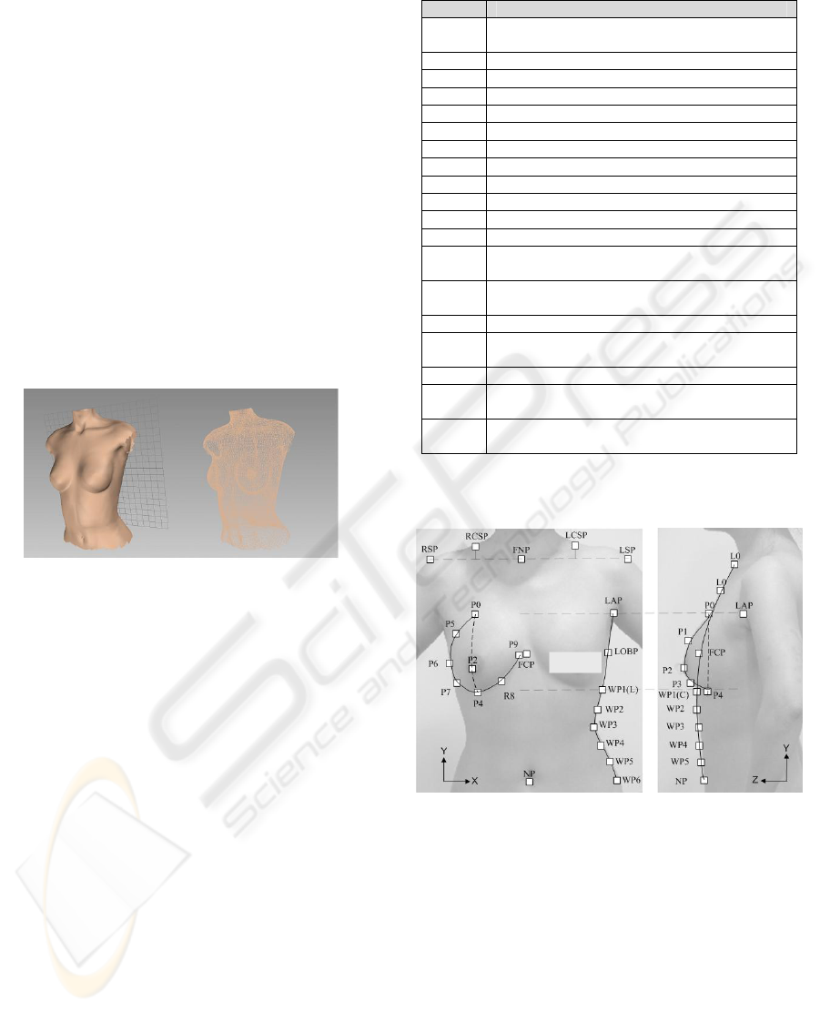
7.0 to make the 3D template model. Figure 1 shows
the template data.
Figure 1: A refined 3D template model: mesh display
mode (left) and wire-frame display mode (right).
2.2 Feature Point Definition
Feature points are necessary and important
prerequisites to get a realistic result in image-based
modeling. We referred to Lee’s definition (H. Lee, K.
Hong and E. Kim, 2004), and excluded some points
and defined some additional points for our purpose.
The number of feature points is 10 for the left and
right breasts, respectively. The two side-view
images are scaled according to the height of the
breast, from P0 to P4, in the front-view image. For
the abdominal part, 18 feature points (six points each
for the left, right and central waist curves,
respectively) are defined. These points are
automatically positioned by skin detection as
described in Section 3.2. Additional points such as
navel, armpit, shoulder, etc. are also defined. Table 1
and Figure 2 show the definitions of the feature
points.
Table 1: The definition of the feature points.
Pt Definition
P0
Upper breast point (UBP),
same y-coord. as LAP on &
P1 Mid-point of P0 & P2 on
P2 Bust point (BP) on &
P3 Mid-point of P2 & P4 on
P4 Bottom breast point (BBP) on &
P5 Mid-point of P0 & P6 on
P6 Outermost point on
P7 Mid-point of P6 & P4 on
P8 Mid-point of P4 & P9 on
P9 Inner breast point (IBP),
FNP Front neck point
SP Shoulder point, same y-coord. as FNP
CSP
Center of shoulder point on ,
mid-point of FNP & SP in x-dir.
OBP
Outer breast point on ,
mid-point of P0 & P4 in y-dir.
WP1 Same y-coord. as P4, on or
WP2
~WP5
Equally dividing points between WP1 and WP6
in y-dir. on or
WP6 Same y-coord. as P4, on or
FCP
Front center point,
Mid-point of LBP9 & RBP9
NP
Navel point,
the same point as WP6 on
: front -view image, : side-view image
: breast curve in
: breast curve in
: waist curve in
: belly curve in
Figure 2: Definitions of the feature points (R: right, L: left,
C: centre).
3 TEMPLATE MODEL
DEFORMATION
3.1 Image Capture
In our image-based 3D torso body modeling, we use
a front-view and two side-view photographs of the
subject. We need both the left-view and right-view
images in order to reconstruct breasts that are not
symmetrical. A back-view photograph is optionally
added if needed for texture mapping. We define the
bf
C
f
I
bs
C
s
I
f
I
s
I
w
C
c
C
f
I
s
I
bf
C
bf
C
bs
C
bf
C
bs
C
bf
C
bf
C
bf
C
w
C
c
C
w
C
c
C
w
C
c
C
bs
C
bf
C
bf
C
bs
C
bf
C
bs
C
c
C
IMAGE-BASED 3D TORSO BODY MODELING - 3D Female Body Modeling for Breast Surgery Simulation
93
feature points from these orthogonal images. The
image for the texture mapping is also obtained from
them. Many postures of the subject were tested
considering the texture mapping and repeatability. A
white or blue background is recommended because
we detect the body curves by skin detection.
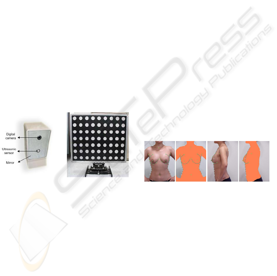
An image-capturing device is designed to get the
photos conveniently even though our software
allows any kind of digital images of subjects. Our
image-capturing device, which is connected to a PC
with a USB cable, consists of a digital camera and a
distance-checking sensor. The image captured by the
digital camera is sent directly to our software.
Olympus SDK v3.3 is applied to implement remote-
capturing (http://www.olympus.com/). An ultrasonic
sensor checks the distance from the object and gives
the distance information to our software. We can
roughly calculate the actual size of the subject using
calibration information according to the distance.
The images of several discrete positions of a
calibration panel are taken beforehand. Our system’s
distance range is 1-2m. Tsai’s calibration method is
applied to derive the relations between the image
coordinates and the world coordinates at each
position. Figure 3 shows our image-capturing device
and the calibration panel.
Figure 3: Photos of the image-capturing device (left) and
the calibration panel (right).
3.2 3D Feature Points’ Calculation
from Images
After taking pictures or loading the images of the
subject, we assign the feature points. All of the
points or each point can be scaled and translated
easily with our GUI. Some points are constrained by
the definition in Table 1, and many of them are
automatically positioned. For example, RSP and
LSP have the same y-coordinates as FNP. Their
coordinates in the front-view image are set at the
outmost positions of the body at the FNP’s y-level.
In Section 2.2, the feature points P0, P2 and P4
in the front-view image are assumed to lie on the
same plane in the 3D coordinate system. These
points are also defined in the side-view. Therefore,
x- and y-coordinates are assigned in the front-view
image and z- and y-coordinates are decided in the
left-view image. Internally, the side-view images are
scaled and normalized according to the front-view.
With these relationships, the coordinates of all the
feature points are derived. Their x-coordinates are
obtained from the front image, and the z-coordinates
are computed from the side image. The y-
coordinates are common values in the front and side
images. The amount of proper deformation of the
template model is obtained by the process of
matching the corresponding feature points in the
template to those in the images. Sections 3.3 and 3.4
describe the algorithms in detail.
WP1~WP6 are detected automatically using skin
detection. We used YCbCr colour space. We need to
handle only Cb and Cr values because we are
interested in the illumination intensity invariant part
of the colour for the skin detection. Eq. (1) below
shows our skin detection criteria:
(1)
where
= 77, = 132
= 133, = 171
In the skin detection process, we have many
small holes in the interior of the body. These holes
are obstacles to finding the body’s curves, so we fill
the holes if they are smaller than a threshold size
proportional to the image size. Figure 4 shows the
skin detection result and the feature points.
Figure 4: Skin detection result and feature points on 2D
front-view (left) and left-view (right) images. Some of the
points are positioned manually and the others are set
automatically.
3.3 Global Deformation
In the global deformation step, we compute the
affine transformation matrix to match the template
model as closely as possible to the feature points
calculated from the images. The affine
transformation includes translation, rotation and
scaling. To minimize the sum of the squared error
between the calculated feature points and the
corresponding feature points of the transformed
model, we use Procrustes Analysis (J.C. Gower and
G.B. Dijksterhuis, 2004). This method is
computationally simple and stable. This global
deformation is an auxiliary step because it gives
min
Cb
max
Cb
min
Cr
max
Cr
}&|),({
maxminmaxmin
CrCrCrCbCbCbyxp <<<
GRAPP 2008 - International Conference on Computer Graphics Theory and Applications
94
good initial conditions for local deformation.
Normalization of the data is also done in this step.
(2)
where
: Feature points calculated from images
: Feature points of template model
S
: scale factor
R
: rotation matrix
T
: translation vector
The procedures of the global deformation are as
follows:
a) Compute the mean of both and .
b) Center each set at its origin.
(i.e., )
c) Compute the norm of each set and .
d) Normalize each set to equal the unit norm.
(i.e.,
e) Let .
f) Compute the Singular Value Decomposition
(SVD) of
A
that results in the matrices L, D
and M.
(i.e.,
)(ASVDLDM =
)
g) Compute the rotation matrix
t
M
LR =
.
h) Compute the scaling factor.
i) Compute the translating vector.
j) Transform to using .
k) Finally, transform the entire 3D template
model’s vertices using
S
,
R
and
T
.
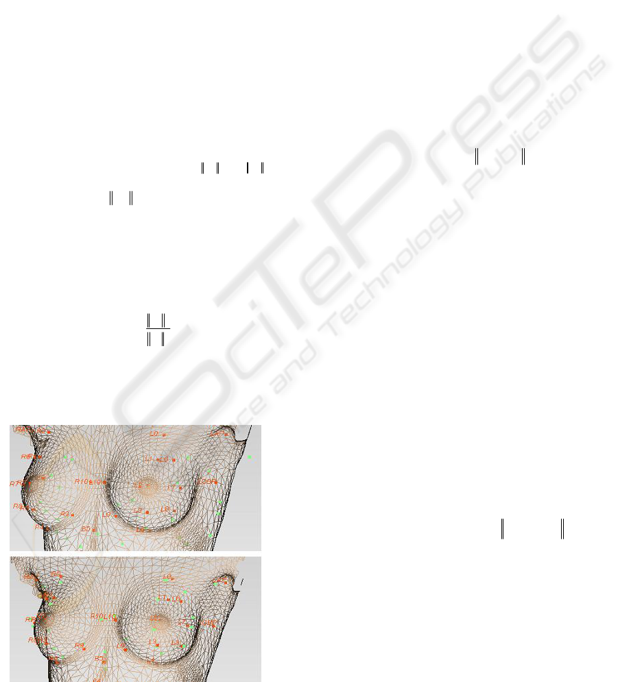
Figure 5: Before and after global deformation; red points
are and green points are .
3.4 Local Deformation
After global rigid deformation aligns the template
model to , local deformation refines and generates
a more realistic model. For this process, an
interpolation function is estimated, and the rest of
the points are mapped using this function. Among
the interpolation methods, Radial Basis Function
(RBF) is a powerful technique for interpolating in a
multidimensional space (Ruprecht and Müller, 1993.,
Carr, et al., 2001., Park, el al., 2005., etc). The basis
function,
R(d)
, depends only on the distance from
the feature points, which are thus called radials. RBF
constructs the interpolant as a linear combination of
basis functions and then determines the coefficients
of the basis functions. The concept of RBF is that
each vertex is influenced by all the feature points,
but the near feature points are more influential on
that vertex.
))(()()(
1
∑
=
−=
N
i
ippRiwpf
(3)
where
)(Pf
: transformed vertex through local deform
w(i)
: coefficients of the basis functions
p(i)
: model’s feature points
p
: each vertex of generic model (input point)
The most common radial basis functions,
R(d)
,
are as follows:
d R(d)
=
(linear)
3
d R(d) =
(cubic)
dlog(d) R(d)
=
(thin plate spline)
u/222
)c(d R(d) +=
(multiquadric)
2
-d/c
e R(d) =
(Gaussian)
We tested those radial basis functions and
selected the most appropriate one for our model:
(4)
To find the coefficients of the basis
functions,
w(i)
, we have Eq. (4) letting
)(
T
Pf
and
C
P
be equal.
(5)
where
j
xC
p
: the x-coordinate of the j
th
calculated feature point
j
xT
p
: the x-coordinate of the j
th
template model feature point
after global deformation
Because we have pairs of and , we can
solve Eq. (5) and get the basis functions’
coefficients.
∑
−=
2
)(),,(min
TC
PPTRSE
T
z
y
x
RS
z
y
x
P
T
T
T
T
T
T
T
+
⎥
⎥
⎥
⎦
⎤
⎢
⎢
⎢
⎣
⎡
⋅=
⎥
⎥
⎥
⎦
⎤
⎢
⎢
⎢
⎣
⎡
=
0
0
0
2
0C
P
2
0T
P
∑
×=
2
2
)(
T
C
P
P
DdiagonalS
)/
2
00 CCC
PPP =
))(()()(
00
RPmeanSPmeanT
TC
−=
00 T
t
C
PPA =
))(()()(
1
∑
=
−==
N
i
j
xTx
j
xTx
j
xC
ippRiwpfp
N 1,2j
…
=
2
50/
)(
d
edR
−
=
j
xT
p
j
xC
p
C
P
T
P
T
P
C
P
C
P
N
C
P
C
P
T
P
)(
0 CCC
PmeanPP −=
TRPSP
TT
+
⋅
⋅=
′
T
P
IMAGE-BASED 3D TORSO BODY MODELING - 3D Female Body Modeling for Breast Surgery Simulation
95
(6)
where
H is a matrix which consist of radial basis function values.
With the same steps above, we deform in the y-
and z-directions also. We apply RBF for all vertices
of template mesh data and finally get the morphed
data according to the subject.
Figure 6: Before and after local deformation from several
views (dot mark: , cross mark: ).
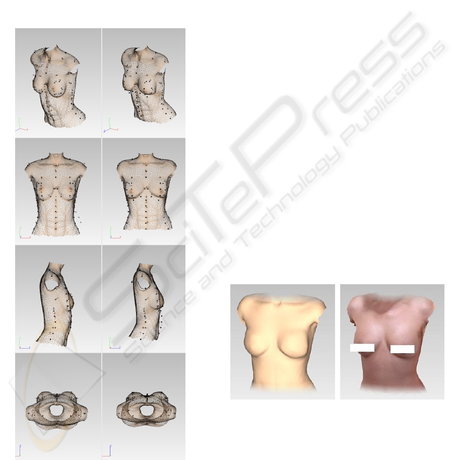
3.5 Texture Mapping
For realism, the texture image is mapped onto the
deformed mesh data. The subject’s front-view and
side-view images are used for texture mapping.
Because we have already assigned feature points on
the images, the texture coordinates of each vertex
are easily calculated. The main issue in texture
mapping is how to blend the three or four orthogonal
images. We checked the normal direction of facets
to decide the blending ratio. Here, let us assume that
we use front-, left- and right-view images for the
texture mapping. The front-view and side-view
images are orthogonal, so the blending ratio is
calculated by the normal vector’s Z component. At
this time, the left image should be used only for the
left part (x>0), and vice versa for the right part.
When we add the back-view image, the blending
algorithm is similar, too. Eq. (7) explains our texture
image blending method in detail.
if x>0 (i.e. left part),
if >0,
else
(7)
if x<0 (i.e. right part),
if <0,
else
where
x
n
K
,
z
n
K
: X and Z component of the normal vector, respectively
The normal vectors are normalized.
f
α
,
l
α
,
r
α
: the blending ratio of front, left and right images
for texture mapping, respectively.
Figure 7: The resulting 3D data from a subject’s
photographs: the geometrical shape (left) and the textured
model (right).
4 RESULTS
This paper proposes an image-based 3D torso
modeling method. A template data is prepared, and
the efficient number and positions of the feature
⎥
⎥
⎥
⎥
⎥
⎥
⎦
⎤
⎢
⎢
⎢
⎢
⎢
⎢
⎣
⎡
=
⎥
⎥
⎥
⎥
⎥
⎥
⎦
⎤
⎢
⎢
⎢
⎢
⎢
⎢
⎣
⎡
−
Cx
N
Cx
Cx
x
x
x
p
p
p
H
Nw
w
w
.
.
)(
.
.
)2(
)1(
2
1
1
zlzf
nn
K
K
−
=
=
1,
α
α
x
n
K
0,1
=
=
lf
α
α
0,1
=
=
rf
α
α
x
n
K
zrzf
nn
K
K
−
=
=
1,
α
α
T
P
C
P
GRAPP 2008 - International Conference on Computer Graphics Theory and Applications
96
points are verified. We have developed and applied
several geometric deforming algorithms and a
texture mapping method to get the subject’s 3D data
from images. We also have designed an image-
capturing device to approximate the actual size. We
can measure dimensions or volumes of a subject’s
data if we reconstruct the 3D data in actual size. The
remote-capturing function enables the operator to
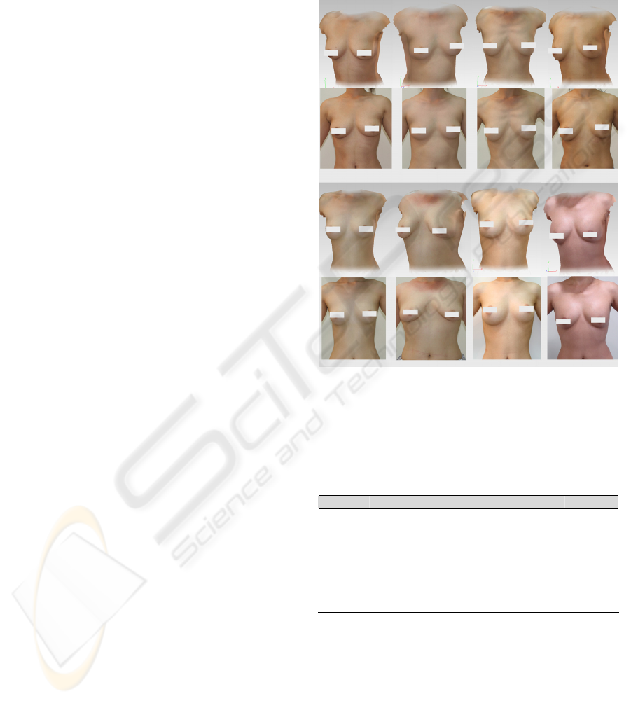
take digital images handily. In Figure 8 shows the
result of our work compared to front-view photos.
As the figure indicates, both the 3D geometry and
texture information of each subject are reconstructed
well for the purpose of visualization.
We analyzed the results by comparing them to
the subjects’ actual 3D scan data. Table 2 shows
those results. RapidForm2002 was used to analysis
the distance errors (http://www.rapidform.com). The
errors are rather big due to the limitations of the
image-based approach. The different postures of the
subjects increased the errors. However, our result is
realistic enough to meet our original goal, which is
virtual simulation of breast surgery. Moreover, our
method requires only three orthogonal images and
needs no expensive hardware. It takes only about a
minute to get the results, starting from capturing a
subject’s photos. We are convinced that the
proposed method can be applied to animation or
other computer graphics with no problem.
To increase the proposed approach’s reliability,
some plastic surgeons and implant retail dealers
have participated and shared their know-how in the
development process.
5 FUTURE WORK
The final goal of this project is to develop a 3D
breast surgery simulation system; thus a new
algorithm is needed to deform a subject’s current 3D
model to see the virtually changed appearance after
the surgery. One possible method for this simulation
would be to use the displacement vectors of the
feature points between before and after the
operation. Our image-based 3D modeling algorithm
will be applied to get subject’s 3D data before and
after plastic surgery for the existing cases. The
relationship between before and after the operation
would be derived by synthesizing or averaging the
transform vectors. Then the deformed feature points
would be obtained from the relationship, and finally
the simulated 3D data would be obtained by
applying RBF interpolation. Because 3D data are
available only if the transformed feature points are
given, this scenario is plausible and reasonable. For
this purpose, we are gathering orthogonal images of
patients before and after plastic surgery. For realistic
simulations, it is also necessary to construct a
database of body shapes according to implant types
and sizes. It would be also possible to make other
cosmetic surgery simulation software for the face
and other parts of the body by extending the scenario
described above.
Figure 8: Examples of eight female subjects. Upper rows
are snapshots of the reconstructed 3D data, and lower rows
show real frontal photos of each subject.
Table 2: Distance errors between the reconstructed data
and the scanned data of the subjects. (unit: [㎜], SD:
standard deviation).
No. Min. Max. Mean SD
1 -14.2 15.3 0.05 5.41
2 -25.0 17.8 0.41 5.45
3 -14.6 20.6 0.57 5.72
4 -24.2 27.5 -0.87 9.23
5 -14.1 13.8 0.28 6.40
6 -19.0 25.5 1.57 7.87
7 -18.3 19.7 0.67 5.91
8 -15.7 13.8 -0.72 5.89
ACKNOWLEDGEMENTS
We would like to thank K&I Technology and
Woorhi Trading for their technical support. We also
appreciate Dr. SungJun Back and Dr. DongRak Lee
for their advice. This work is financially supported
by the Ministry of Education and Human Resources
Development (MOE), the Ministry of Commerce,
Industry and Energy (MOCIE) and the Ministry of
IMAGE-BASED 3D TORSO BODY MODELING - 3D Female Body Modeling for Breast Surgery Simulation
97

Labor (MOLAB) through the fostering project of the
Lab of Excellency. This research was also supported
in part by the Institute of Advanced Machinery and
Design at Seoul National University.
REFERENCES
W. Lee and N. Magnenat-Thalmann, 2000. Fast head
modeling for animation. Journal Image and Vision
Computing.
M. Zhang, el al., 2004. Image-Based 3D Face Modeling.
Proceeding of the International Conference on
CGIV’04.
R. Balaniuk, I. Costa and J. Melo, 2006. Cosmetic Breast
Surgery Simulation. VIII Symposium on Virtual
Reality - SVR2006.
W. Lee, J. Gu and N. Magnenat-Thalmann, 2000.
Generation Animatable 3D Virtual Humans from
Photographs. Computer Graphics Forum
(Eurographics 2000).
J.C. Gower and G.B. Dijksterhuis, 2004. Procrustes
Problems, Oxford University Press.
A.N. Ansari and M. Abdel-Mottaleb, 2003. 3-D Face
Modeling Using Two Views and a Generic Face
Model with Application to 3-D Face Recognition. In
Proceedings of the IEEE Conference on Advanced
Video and Signal Based Surveillance.
U. Neumann, el al., 1999. Constructing a Realistic Head
Animation Mesh for a Specific Person. USR-TR.
J.C. Carr, et al., 1997. Surface interpolation with radial
basis functions for medical imaging. IEEE
Transactions Medical Imaging.
D. Ruprecht and H. Müller, 1993. Free form deformation
with scattered data interpolation methods. Geometric
Modelling (Computing Supplement 8), Springer
Verlag., Wien.
R.Y. Tsai, 1987. A Versatile Camera Calibration
Technique for High-Accuracy 3D Machine Vision
Metrology Using Off-the-Shelf TV Cameras and Lens.
IEEE Journal of Robotics and Automation.
A. Hilton, D. Beresford, T. Gentils, R. Smith and W. Sun,
1999. Virtual People: Capturing Human Models to
Populate Virtual Worlds. Computer Animation,
Geneva, Switzerland.
T. Goto, W. Lee and N. Magnenat-Thalmann, 2002. Facial
feature extraction for quick 3D face modeling. Signal
processing: Image communication.
W. Lee, P. Kalra and N. Magnenat-Thalmann, 1997.
Model Based Face Reconstruction for Animation. In
Proc. Multimedia Modeling (MMM'97).
J. Noh, D. Fidaleo and U. Neumann, 2000. Animated
Deformations with Radial Basis Functions. ACM
Virtual Reality and Software Technology (VRST).
J.C. Carr, el al., 2001. Reconstruction and Representation
of 3D Objects with Radial Basis Functions. Annual
Conference Series.
I.K. Park, el al., 2005. Image-Based 3D Face Modeling
System. EURASIP Journal on applied signal
processing.
H. Lee, K. Hong and E. Kim, 2004. Measurement protocol
of women’s nude breasts using a 3D scanning
technique. Applied Ergonomics 35.
H. Seo, F. Cordier and K. Hong, 2007. A breast modeler
base on analysis of breast scans. Computer Animation
and Virtual Worlds 2007.
GRAPP 2008 - International Conference on Computer Graphics Theory and Applications
98
