
QUASI-CONVOLUTION PYRAMIDAL BLURRING
Martin Kraus
Computer Graphics and Visualization Group, Technische Universit¨at M¨unchen, Boltzmannstr. 3, Garching, Germany
Keywords:
Rendering, image processing, blurring, pyramid algorithm, GPU, real-time.
Abstract:
Efficient image blurring techniques based on the pyramid algorithm can be implemented on modern graph-
ics hardware; thus, image blurring with arbitrary blur width is possible in real time even for large images.
However, pyramidal blurring methods do not achieve the image quality provided by convolution filters; in
particular, the shape of the corresponding filter kernel varies locally, which potentially results in objectionable
rendering artifacts. In this work, a new analysis filter is designed that significantly reduces this variation for
a particular pyramidal blurring technique. Moreover, an efficient implementation for programmable graph-
ics hardware is presented. The proposed method is named “quasi-convolution pyramidal blurring” since the
resulting effect is very close to image blurring based on a convolution filter for many applications.
1 INTRODUCTION AND
RELATED WORK
As the programmability of graphics processing units
(GPUs) allows for the implementation of increasingly
complex image processing techniques, many effects
in real-time rendering are nowadays implemented
as post-processing effects. Examples include tone
mapping (Goodnight et al., 2003), glow (James and
O’Rorke, 2004), and depth-of-field rendering (De-
mers, 2004; Hammon, 2007; Kraus and Strengert,
2007a). Many of these real-time effects require ex-
tremely efficient image blurring; for example, depth-
of-field rendering is often based on multiple blurred
versions of a pinhole image. Thus, full-screen images
have to be blurred with potentially large blur filters
multiple times per frame at real-time frame rates.
Unfortunately, convolution filters cannot provide
the required performance for large blur filters and
the Fast Fourier Transformation (FFT) is not effi-
cient enough for large images. As shown by Burt
(Burt, 1981), the pyramid algorithm provides a bet-
ter complexity than the FFT for blurring; therefore,
many real-time depth-of-field rendering techniques
employ pyramid methods in one way or another. For
example, Demers (Demers, 2004) uses a mip map
(Williams, 1983) to generate multiple, downsampled,
i.e., pre-filtered, versions of a pinhole image. Ham-
mon (Hammon, 2007) computes only one downsam-
pled level to accelerate the blurring with filters of
medium size, while Kraus and Strengert (Kraus and
Strengert, 2007a) employ a full pyramid algorithm for
the blurring of sub-images, which are computed by a
decomposition of a pinhole image according to the
depth of its pixels.
The specific analysis filters and synthesis filters
for the pyramid algorithm are often determined by
trial-and-error, i.e., the filter size is increased at the
cost of memory bandwidth until a sufficient image
quality is achieved. A more thorough exploration
of appropriate filter designs and their efficient imple-
mentation on GPUs has been provided by Kraus and
Strengert (Kraus and Strengert, 2007b), which im-
proved the pyramidal blurring on GPUs presented by
Strengert et al. (Strengert et al., 2006). This improved
method is summarized in Section 2.
The first contribution of this work is a quantitative
analysis of the filters proposed by Kraus and Strengert
by means of response functions in Section 3, which
reveal strong local variations of the corresponding
blur filter due to the grid structure of the image pyra-
mid. This shortcoming can result in objectionable
rendering artifacts; for example, it causes pulsating
artifacts if a moving pixel (or a small group of con-
sistently moving pixels) of high contrast is blurred in
an animated sequence since the blur depends on the
pixel’s position within the image.
To overcome this deficiency of pyramidal blur-
ring, a new analysis filter is designed in Section 4,
which is the second contribution of this work. It re-
duces the variations of the corresponding blur filter
considerably—in particular the variation of its max-
imum amplitude. Thus, the pyramidal blurring pro-
posed in this work is significantly closer to blurring
155
Kraus M. (2008).
QUASI-CONVOLUTION PYRAMIDAL BLURRING.
In Proceedings of the Third International Conference on Computer Graphics Theory and Applications, pages 155-162
DOI: 10.5220/0001094401550162
Copyright
c
SciTePress
by a convolution filter and is therefore called “quasi-
convolution pyramidal blurring.”
In addition to the two mentioned contributions, an
efficient GPU implementation of the new analysis fil-
ter is described in Section 5, while some experiments
demonstratingthe benefits of the proposed method are
presented in Section 6.
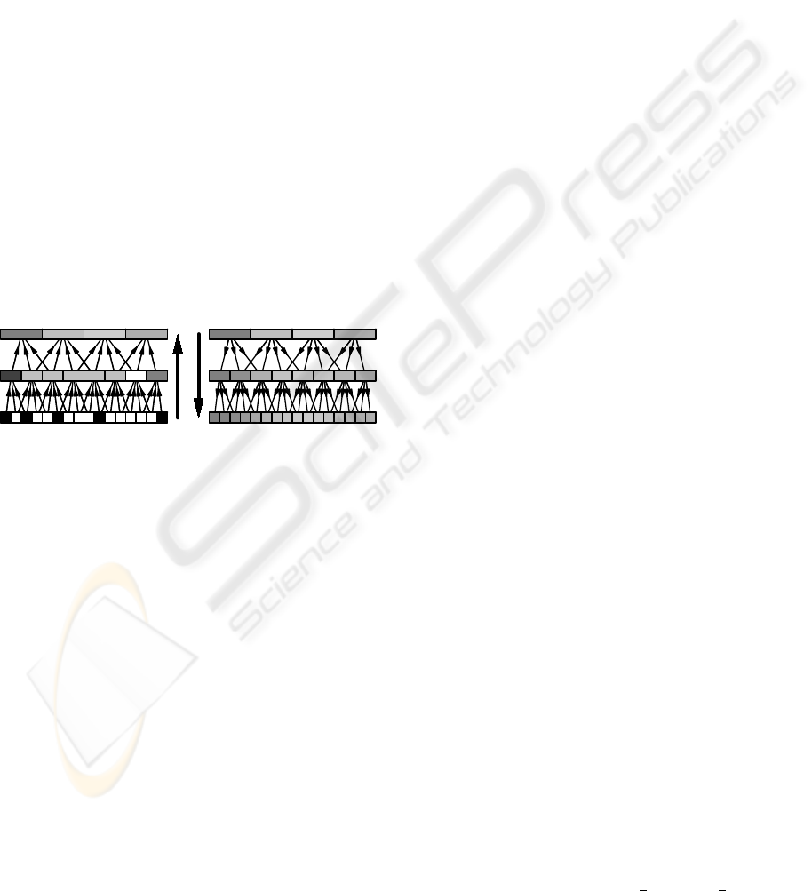
2 PYRAMIDAL BLURRING
Image blurring with the pyramid algorithm was first
suggested by Burt (Burt, 1981). In the first part of the
method, called analysis, an image pyramid of down-
sampled or reduced image levels is computed by ap-
plying a (usually small) analysis filter mask and sub-
sampling the result by a factor of 2 in each dimension.
In the second part of the method, called synthesis,
one of the levels is chosen based on the specified blur
width. The coarse image of the chosen level is itera-
tively upsampled to the original dimensions by apply-
ing a synthesis filter. Figure 1 illustrates this method
for a one-dimensional image of 16 pixels.
analysis synthesis
Figure 1: Illustration of pyramidal blurring in 1D.
An efficient GPU implementation of this algo-
rithm was presented by Strengert et al. (Strengert
et al., 2006) for a 2× 2 box analysis filter and a syn-
thesis filter that corresponds to filtering the coarse im-
age by a biquadratic B-spline filter. The resulting
image quality can be improved by applying a 4 × 4
box analysis filter or an analysis filter corresponding
to a biquadratic B-spline filter as suggested by Kraus
and Strengert (Kraus and Strengert, 2007b). While
this improvement often results in an acceptable image
quality when blurring static images, rendering arti-
facts become visible in animations since the proposed
pyramidal blur deviates significantly from blurring by
convolution filtering, i.e., the blur varies depending
on the image position.
In this work, the deviation from convolutionfilters
is quantitatively analyzed and a new analysis filter is
designed that allows for an efficient GPU implemen-
tation while minimizing the deviation from a convo-
lution filter. We employ the synthesis filter proposed
by Strengert et al. since biquadratic B-spline filter-
ing offers several interesting features such as compact
support, C
1
continuity, similarity to a Gaussian distri-
bution function and therefore almost radial symme-
try, and the possibility of an efficient implementation
based on bilinear interpolation (Strengert et al., 2006).
3 QUANTITATIVE ANALYSIS OF
RESPONSE FUNCTIONS
In order to analyze the deviation of pyramidal blur-
ring from convolution filtering, we consider the con-
tinuous limit case of infinitely many downsampling
and upsampling steps; thus, the “pixels” of the input
image are infinitely small. Without loss of generality,
the size of a pixel of the coarsest image level, which is
used as input for the synthesis, is set to 1 and the sam-
pling positions of these pixels are positioned at integer
coordinates. We discuss only one-dimensional gray-
scale images since the extension to two-dimensional
color images is straightforward for separable filters
and linear color spaces.
The limit of infinitely small input pixels allows us
to define continuous response functions for a black
input image with a single, infinitely small intensity
peak at position p ∈ R in a coordinate system where
the pixels of the coarsest image level are at integer
coordinates. We distinguish between two kinds of re-
sponse functions: the first is denoted by ϕ
i
(p) and
specifies the intensity of a pixel of the coarsest image
level at integer position i ∈ Z after downsampling the
input image with a peak at position p.
The second kind of response functions is denoted
by ψ(x, p) and specifies the intensity of the blurred
image (of infinitely high resolution) at position x ∈ R
for a peak at position p ∈ R. In this work, the blurred
image is always obtained by filtering the coarsest im-
age level by a quadratic B-spline. We denote the
quadratic B-spline function centered at i by ϕ
quad
i
(x)
(see Equation 5 for its definition); thus, ψ(x, p) is
defined as the sum over all pixels of the product of
the response function for the i-th pixel ϕ
i
(p) with the
quadratic B-spline ϕ
quad
i
(x).
ψ(x, p) =
∑
i
ϕ
i
(p)ϕ
quad
i
(x) (1)
With the help of these definitions we compute
ϕ
i
(p) and ψ(x, p) for three analysis filters discussed
by Kraus and Strengert (Kraus and Strengert, 2007b).
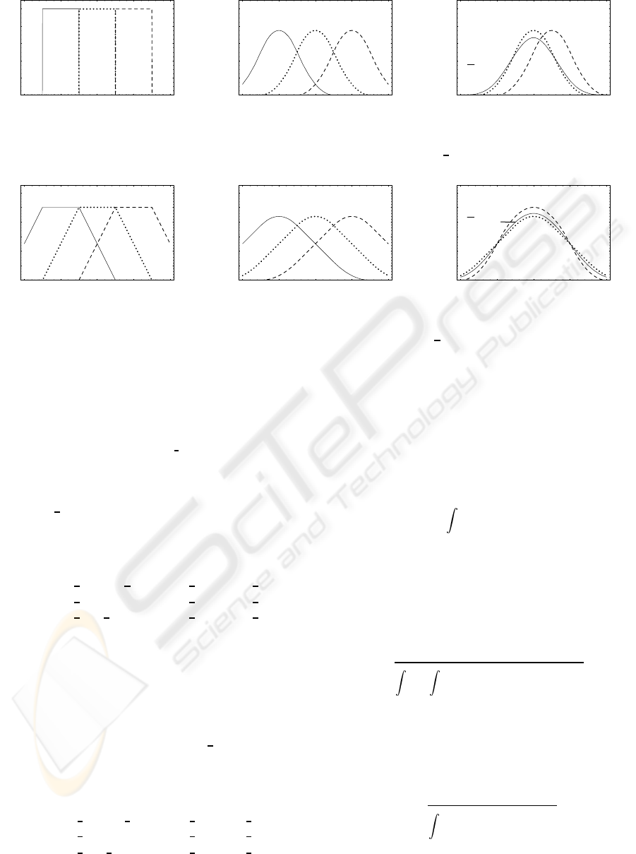
The analysis filter mask for the 2-tap box filter is
1
2
(1 1); thus, the corresponding response function for
the i-th pixel of the coarsest image level is a simple
rectangle function denoted by ϕ
rect
i
(p) and depicted
in Figure 2a.
ϕ
rect
i
(p) =
1 if i−
1
2
< p < i+
1
2
0 otherwise
(2)
GRAPP 2008 - International Conference on Computer Graphics Theory and Applications
156
-2 -1 0 1 2
x
0.2
0.4
0.6
0.8
1
j
-1
rect
HxL j
0
rect
HxL j
+1
rect
HxL
(a)
-2 -1 0 1 2
x
0.2
0.4
0.6
0.8
1
Ψ
rect
Hx,-1L Ψ
rect
Hx,0L Ψ
rect
Hx,+1L
(b)
-2 -1 0 1 2
y
0.2
0.4
0.6
0.8
1
Ψ
rect
HyL
Ψ
rect
Hy,0L
Ψ
rect
Hy+12,12L
(c)
Figure 2: Response functions for the 2-tap box analysis filter
1
2
(1 1).
-2 -1 0 1 2
x
0.1
0.2
0.3
0.4
0.5
0.6
j
-1
trap
HxL j
0
trap
HxL j
+1
trap
HxL
(a)
-2 -1 0 1 2
x
0.1
0.2
0.3
0.4
0.5
0.6
Ψ
trap
Hx,-1L Ψ
trap
Hx,0L Ψ
trap
Hx,+1L
(b)
-2 -1 0 1 2
y
0.1
0.2
0.3
0.4
0.5
0.6
Ψ
trap
HyL
Ψ
trap
Hy,0L
Ψ
trap
Hy+12,12L
(c)
Figure 3: Response functions for the 4-tap box analysis filter
1
4
(1 1 1 1).
The corresponding response function ψ
rect
(x, p)
for the blurred image is a quadratic B-spline centered
at the integer coordinate closest to the peak position
p.
ψ
rect
(x, p) = ϕ
quad
⌊
p+
1
2
⌋
(x) (3)
This function is illustrated in Figure 2b.
In the case of the 4-tap box analysis filter with the
filter mask
1
4
(1 1 1 1), the shape of the response func-
tion for the i-th pixel is a trapezoid as illustrated in
Figure 3a; therefore, the response function is denoted
by ϕ
trap
i
(p).
ϕ
trap
i
(p) =
1
2
(p− i+
3
2
) if i−
3
2
< p < i−
1
2
1
2
if i−
1
2
≤ p ≤ i+
1
2
1
2
(i+
3
2
− p) if i+
1
2
< p < i+
3
2
0 otherwise
(4)
The corresponding response function for the
blurred image is denoted by ψ
trap
(x, p) and illustrated
in Figure 3b for integer values of p. It should be noted
that non-integer values of p result in different shapes
as illustrated in Figure 3c for p = 1/2.
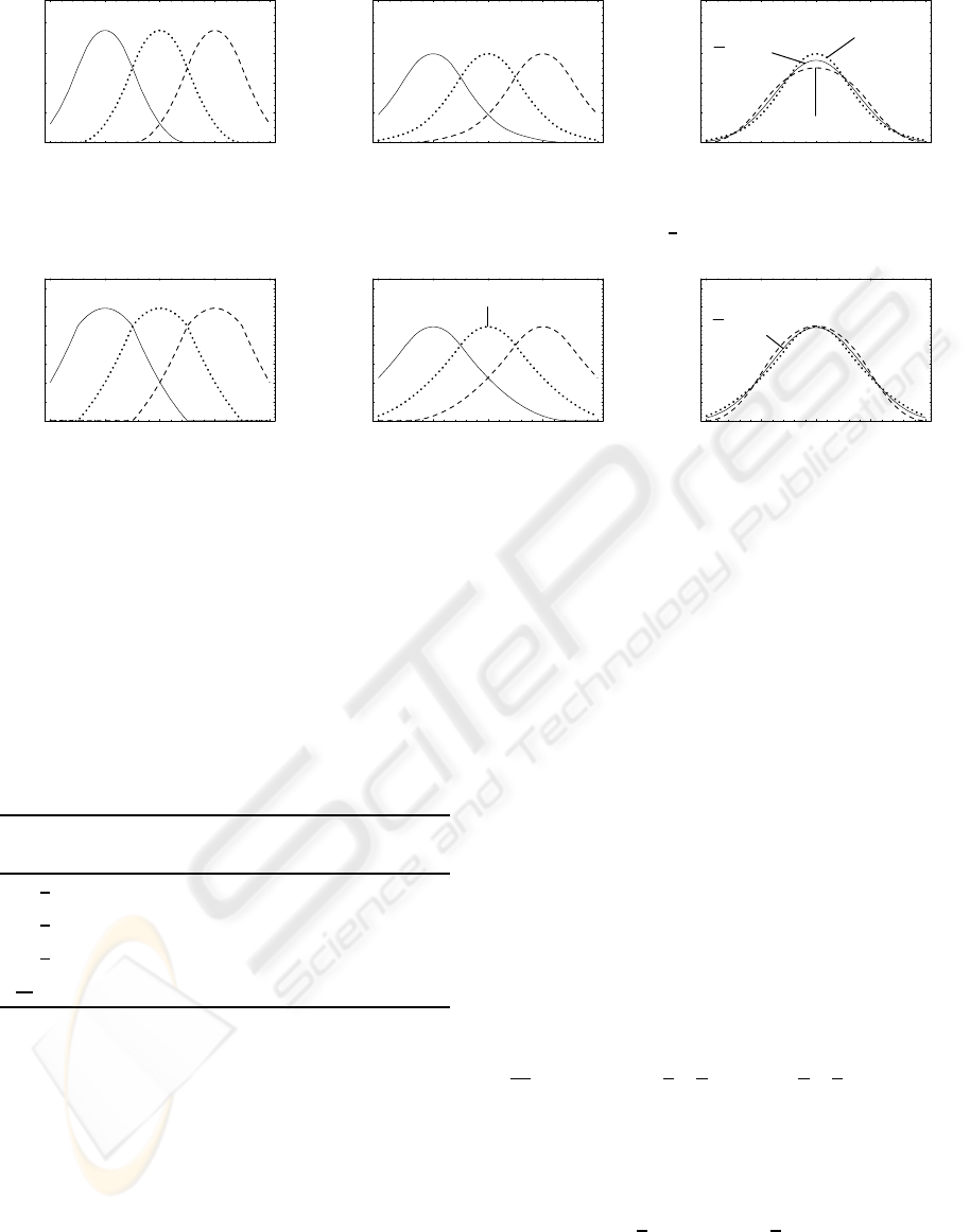
For the 4-tap analysis filter mask
1
8
(1 3 31), the
response function for the i-th pixel is a quadratic B-
spline, which is denoted by ϕ
quad
i
and illustrated in
Figure 4a.
ϕ
quad
i
(p) =
1
2
p− i+
3
2
2
if i−
3
2
< p < i−
1
2
3
4
− (p− i)
2
if i−
1
2
≤ p ≤ i+
1
2
1
2
i+
3
2
− p
2
if i+
1
2
< p < i+
3
2
0 otherwise
(5)
Correspondingly, the response function for the
blurred image is denoted by ψ
quad
(x, p). An illustra-
tion for integer values of p is given in Figure 4b.
In order to compare the response functions
ψ(x, p), which depend on x and p, with convolution
filters that only depend on the difference y
def
= x − p,
we define an averaged response function
¯
ψ(y) by in-
tegration over p.
¯
ψ(y) =
1
0
dp ψ(y+ p, p) (6)
The corresponding functions
¯
ψ
rect
(y),
¯
ψ
trap
(y),
and
¯
ψ
quad
(y) are illustrated in Figures 2c, 3c, and 4c.
With the help of
¯
ψ(y) the deviation of a particu-
lar pyramidal blurring method from convolution blur-
ring can be quantified by computing the root mean
square deviation (RMSD), denoted by ε, between the
response function ψ(x, p) and
¯
ψ(x− p).
ε =
s
1
0
dp
+∞
−∞
dx (ψ(x, p) −
¯
ψ(x − p))
2
(7)
Additionally, we consider the RMSD between
ψ(p, p) and
¯
ψ(0), denoted by ε
0
, since a variation of
the maximum amplitude of a blur filter is more easily
perceived than a variation at other positions and all
averaged response functions
¯
ψ(y) considered in this
work achieve their maxium for y = 0.
ε
0
=
s
1
0
dp (ψ(p, p)−
¯
ψ(0))
2
(8)
Actual values of ε and ε
0
for ψ
rect
(x, p),
ψ
trap
(x, p), and ψ
quad
(x, p) are given in Table 1. Due
QUASI-CONVOLUTION PYRAMIDAL BLURRING
157
-2 -1 0 1 2
x
0.2
0.4
0.6
0.8
j
-1
quad
HxL j
0
quad
HxL j
+1
quad
HxL
(a)
-2 -1 0 1 2
x
0.2
0.4
0.6
0.8
Ψ
quad
Hx,-1L Ψ
quad
Hx,0L Ψ
quad
Hx,+1L
(b)
-2 -1 0 1 2
y
0.2
0.4
0.6
0.8
Ψ
quad
HyL
Ψ
quad
Hy,0L
Ψ
quad
Hy+12,12L
(c)
Figure 4: Response functions for the quadratic analysis filter
1
8
(1 3 31).
-2 -1 0 1 2
x
0.1
0.2
0.3
0.4
0.5
0.6
0.7
j
-1
quasi
HxL j
0
quasi
HxL j
+1
quasi
HxL
(a)
-2 -1 0 1 2
x
0.1
0.2
0.3
0.4
0.5
0.6
0.7
Ψ
quasi
Hx,-1L
Ψ
quasi
Hx,0L
Ψ
quasi
Hx,+1L
(b)
-2 -1 0 1 2
y
0.1
0.2
0.3
0.4
0.5
0.6
0.7
Ψ
quasi
HyL
Ψ
quasi
Hy,0L
Ψ
quasi
Hy+12,12L
(c)
Figure 5: Response functions for the proposed quasi-convolution analysis filter 1/64 (13 19 19 13).
to the strong deviation of ψ
rect
(x, p) from a convolu-
tion filter, it is rather unsuited for pyramidal blurring
as already observed by Kraus and Strengert. Inter-
estingly, ψ
quad
(x, p) provides no improvement com-
pared to ψ
trap
(x, p) although ϕ
quad
i
(p) is C
1
continu-
ous while ϕ
trap
i
(p) is only C
0
continuous.
Table 1: RMS deviation ε of response functions from an
averaged filter and the RMSD ε
0
at the center of the filter.
analysis response
mask function ε ε
0
1
2
(0 1 10) ψ
rect
(x, p) 0.2658 0.0745
1
4
(1 1 11) ψ
trap
(x, p) 0.0376 0.0186
1
8
(1 3 31) ψ
quad
(x, p) 0.0510 0.0327
1
64
(13 19 1913) ψ
quasi
(x, p) 0.0276 0.0027
4 QUASI-CONVOLUTION
PYRAMIDAL BLURRING
In order to design a pyramidal blurring method that
produces a blur that is visually similar to convolution
filtering, we try to minimize ε and ε
0
defined in Equa-
tions 7 and 8 under several constraints; in particular,
we will employ the synthesis filter corresponding to
quadratic B-spline filtering. Moreover, we consider
only symmetric 4-tap analysis filter masks; i.e., filter
masks of the form (a (1/2− a) (1/2− a) a).
By numeric methods we determined the mini-
mum of ε under these constraints for a approxi-
mately equal to 13/64; i.e., for the analysis filter mask
1/64 (13 19 19 13). The minimum of ε
0
is achieved
for a slightly larger value of a; however, the potential
improvement is less than 5%; thus, we will neglect
it in this work. We call the corresponding blurring
method “quasi-convolution pyramidal blurring” since
this analysis filter reduces ε and ε
0
significantly as
shown in Table 1. Of particular interest is the strong
decrease of ε
0
, which is almost an order of magnitude
smaller than for previously suggested pyramidal blur-
ring methods.
It is an interesting feature of the analysis filter
mask for quasi-convolution pyramidal blurring that it
can be constructed by a linear combination of the 4-
tap box filter and the analysis filter mask for quadratic
B-splines:
1
64
(13 19 19 13) =
5
8
×
1
4
(1 1 1 1)+
3
8
×
1
8
(1 3 3 1). (9)
Therefore, the response function ψ
quasi
(x, p) can
be computed as the same linear combination of the
corresponding response functions due to the linearity
of the pyramid method:
ψ
quasi
(x, p) =
5
8
× ψ
trap
(x, p) +
3
8
× ψ
quad
(x, p). (10)
The response functions ϕ
quasi
i
(x) and ψ
quasi
(x, p) are
illustrated in Figures 5a and 5b while
¯
ψ
quasi
(y) is de-
picted in Figure 5c. In comparison to Figures 3c and
GRAPP 2008 - International Conference on Computer Graphics Theory and Applications
158
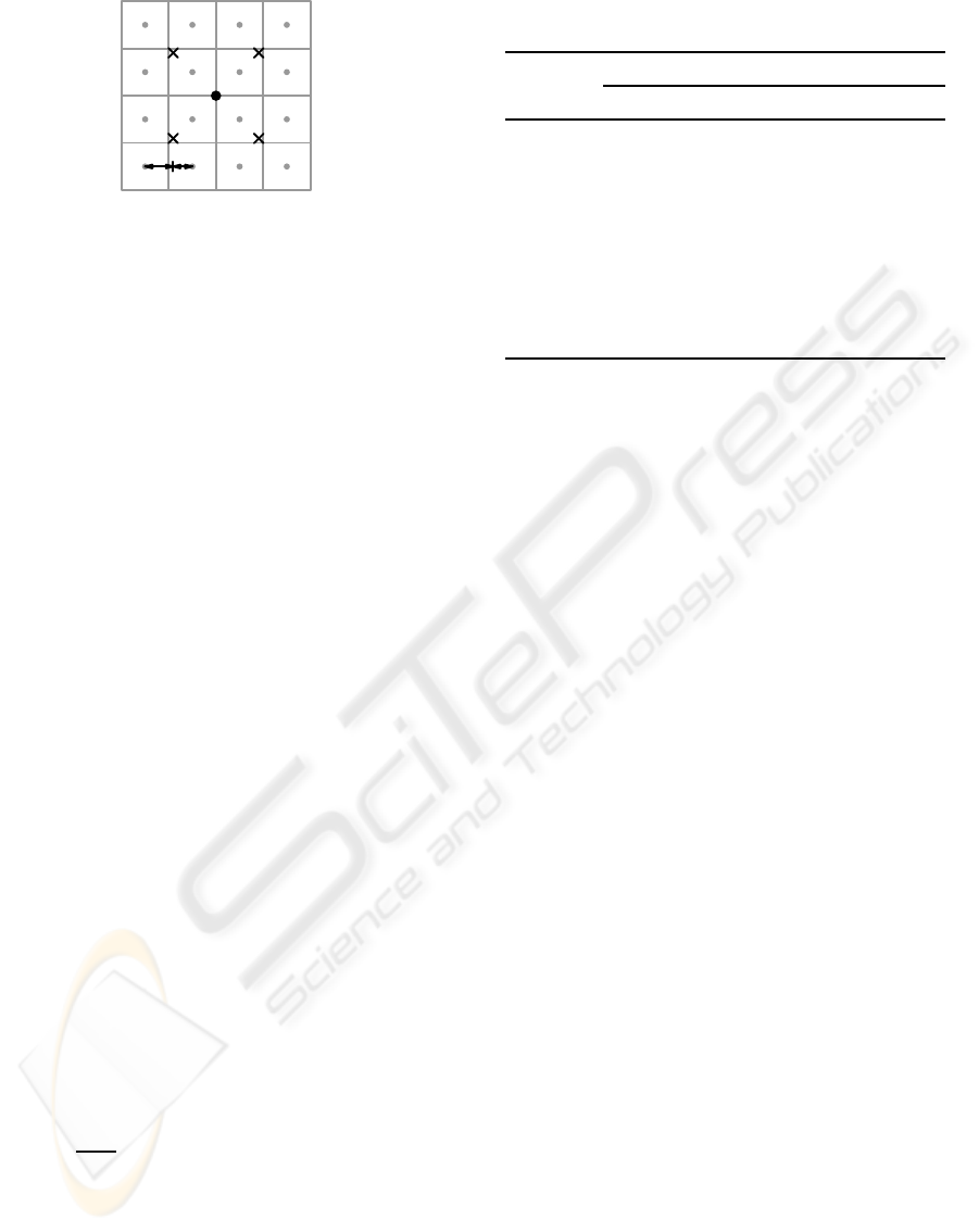
19 :13
Figure 6: Illustration of the positions (crosses) of four bi-
linear texture lookups for the quasi-convolution analysis fil-
ter. The centers of texels of the finer level are indicated by
grey dots, while the black dot indicates the center of the
processed texel of the coarser image level.
4c, a strong reduction of the deviation of ψ
quasi
(y,0)
and ψ
quasi
(y+ 1/2,1/2) from
¯
ψ
quasi
(y) is obvious.
It should be noted that our results depend on sev-
eral constraints, in particular the width of the analysis
filter and the particular synthesis filter, which were
both chosen to allow for an efficient GPU implemen-
tation as discussed in the next section. Wider analy-
sis and synthesis filters are likely to allow for even
smaller values of ε and ε
0
, however, at higher compu-
tational costs at run time.
5 GPU IMPLEMENTATION
Sigg and Hadwiger (Sigg and Hadwiger, 2005)
have proposed an efficient way of exploiting GPU-
supported bilinear interpolation for cubic B-spline fil-
tering. We can employ an analogous technique to
compute the analysis filter mask 1/64 (13 19 19 13)
by two linear interpolations. To this end the posi-
tion of the first linear filtered texture lookup has to be
placed between the first and second pixels at distances
in the ratio 19:13 and the second lookup between the
third and fourth at distances in the ratio 13:19. The
mean of the two texture lookups is the correctly fil-
tered result in the one-dimensional case.
For two-dimensional images, the analysis filter
mask for quasi-convolution blurring is constructed by
a tensor product of the one-dimensional filter mask:
1
4096
169 247 247 169
247 361 361 247
247 361 361 247
169 247 247 169
(11)
In this case, four bilinear texture lookups are neces-
sary. Similarly to the one-dimensional case, the posi-
tions are placed at distances in the ratio 19:13 in hor-
izontal and vertical direction, where the pixels closer
to the center of the filter mask are also closer to the
positions of the texture lookups. These positions (ac-
Table 2: Timings for blurring a 1024 × 1024 4 × 16-bit
RGBA image on a GeForce 7900 GTX.
pyramid analysis filter
levels 2× 2 box 4× 4 box quasi-conv.
1 0.40 ms 0.57ms 0.85ms
2 0.65 ms 0.82ms 1.27ms
3 0.72 ms 0.89ms 1.39ms
4 0.76 ms 0.92ms 1.44ms
5 0.77 ms 0.94ms 1.47ms
6 0.78 ms 0.95ms 1.49ms
7 0.80 ms 0.96ms 1.51ms
cording to the OpenGL conventions for texture coor-
dinates) are illustrated in Figure 6. The filtered result
is computed by the mean of the four texture lookups.
For comparison, we also discuss implementations
of the 2 × 2 box analysis filter, the 4× 4 box analy-
sis filter, and the biquadratic analysis filter. The 2× 2
box filter mask can be implemented very efficiently
by a single bilinear texture lookup positioned equidis-
tantly between the centers of the four relevant texels.
The most efficient way to implement the 4×4 box fil-
ter mask is a two-pass method with only two bilinear
texture lookups (Kraus and Strengert, 2007b). For the
biquadratic analysis filter, a variant of the presented
implementation of the quasi-convolution analysis fil-
ter with adapted positions appears to provide the best
performance. Thus, the biquadratic analysis filter and
the quasi-convolution analysis filter achieve the same
performance.
Measured timings for these implementations are
summarized in Table 2 for blurring a 1024× 1024 im-
age. The number of pyramid levels determines the
width of the blur; it corresponds to the number of per-
formed analysis steps, which is equal to the number
of synthesis steps. The employed synthesis filter cor-
responds to biquadratic B-spline filtering and can be
implemented with only one bilinear lookup (Strengert
et al., 2006).
6 RESULTS
Figures 7 to 10 illustrate the pyramidal blurring of
an antialiased line by two pyramid levels. Analo-
gously to Figure 1, the two downsampling steps of
the analysis are depicted on the left-hand-side(bottom
up) while the two upsampling steps of the synthesis
are shown on the right-hand-side (top down). Thus,
the blurred result is shown in the lower, right image
QUASI-CONVOLUTION PYRAMIDAL BLURRING
159
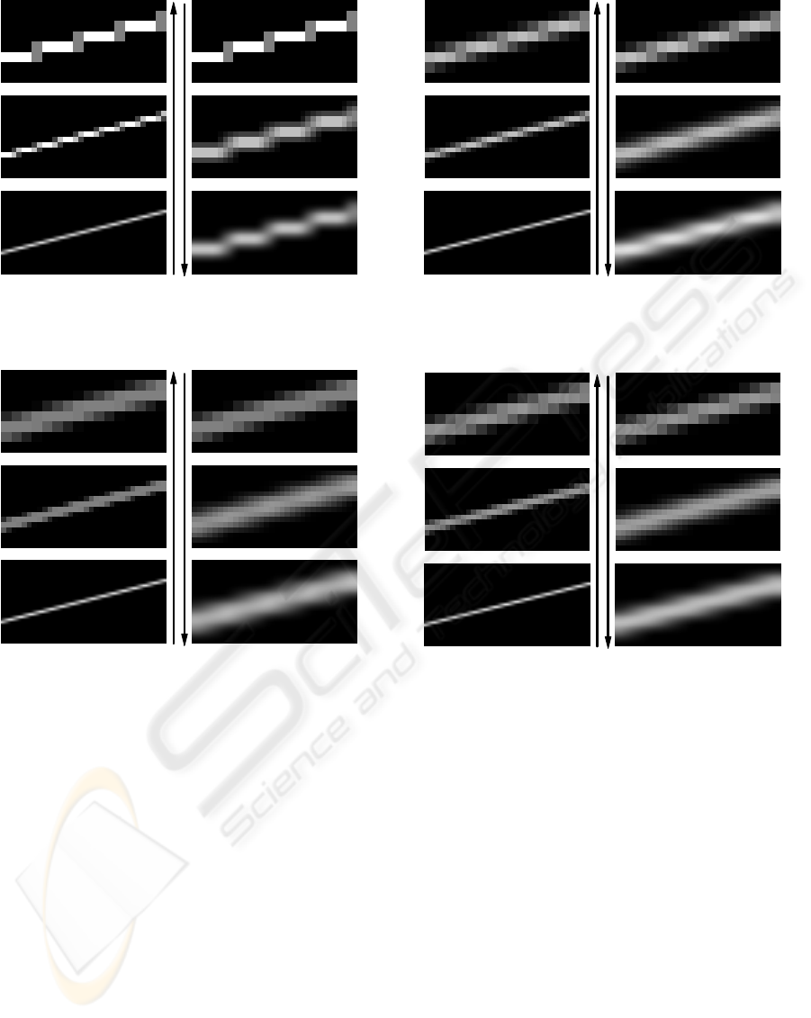
Figure 7: Pyramidal blurring of an antialiased line with the
2× 2 box analysis filter.
Figure 8: Pyramidal blurring of an antialiased line with the
4× 4 box analysis filter.
of each figure. Linear intensity scaling was employed
to enhance the images; however, the same scaling of
intensities was employed in corresponding images of
Figures 7, 8, 9, and 10.
Blurring with the 2 × 2 box analysis filter in Fig-
ure 7 results in strong staircasing artifacts in the lower,
right image. The biquadratic analysis filter employed
in Figure 9 also results in a clearly visible oscillation
of the blurred line’s intensity. Similar oscillations also
occur in animations, where they are often more objec-
tionable since their position is aligned with the pyra-
midal grid, i.e, they often result in fixed-pattern dis-
tortions of the processed images.
The 4 × 4 box filter employed in Figure 8 and
the quasi-convolution filter used in Figure 10 produce
significantly better results than the biquadratic analy-
sis filter. Unfortunately, the employed linear inten-
sity scaling cannot reveal the differences between Fig-
Figure 9: Pyramidal blurring of an antialiased line with the
biquadratic analysis filter.
Figure 10: Pyramidal blurring of an antialiased line with the
quasi-convolution analysis filter.
ures 8 and 10. Therefore, additional nonlinear con-
trast enhancement was employed in Figure 13 to com-
pare the resulting images of the blurred line. The
left image in Figure 13 reveals an oscillation of in-
tensity for the 4 × 4 box filter, while the line blurred
with quasi-convolution in the right image of Figure 13
shows almost no such oscillation for the same im-
age enhancement settings. Although nonlinear im-
age enhancement is necessary to show these differ-
ences, their relevance should not be underestimated
since several image post-processing techniques (e.g.,
for tone mapping) use blurred intermediate images in
nonlinear computations; thus, even small-scale arti-
facts can become objectionable.
To compare quasi-convolution blurring with ac-
tual convolution filtering, Figure 14 shows the two-
dimensional convolution of the image of an an-
tialiased line with the averaged filter
¯
ψ
quasi
of quasi-
GRAPP 2008 - International Conference on Computer Graphics Theory and Applications
160
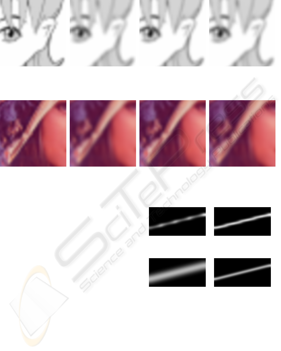
(a) (b) (c) (d)
Figure 11: Detail of a Manga image (http://commons.wikimedia.org/wiki/Image:Manga.png) blurred with (a) the 2× 2 box
analysis filter, (b) the 4× 4 box analysis filter, (c) the biquadratic analysis filter, and (d) the quasi-convolution analysis filter.
(a) (b) (c) (d)
Figure 12: Detail of the 512× 512 Lenna image blurred with (a) the 2× 2 box analysis filter, (b) the 4× 4 box analysis filter,
(c) the biquadratic analysis filter, and (d) the quasi-convolution analysis filter.
convolution blurring.
Figures 11 and 12 show details of actual images,
which were blurred by the presented methods. While
the staircasing artifacts generated by the 2 × 2 box
analysis filter are clearly visible in Figures 11a and
12a, the artifacts generated by the quadratic analy-
sis filter in Figures 11c and 12c are less obvious.
Applying the 4 × 4 box analysis filter or the quasi-
convolution filter results in even less artifacts, which
are usually not perceivable in static images such as
Figures 11b, 11d, 12b, and 12d. However, they are
more easily perceived if the blurred image is trans-
lated with respect to the pyramidal grid in an anima-
tion.
This comparison approves the results of our quan-
titative analysis in Section 3; in particular, the bi-
quadratic analysis filter appears to provide no advan-
tages in comparison to the 4×4 box filter or the quasi-
convolution filter. The improved image quality pro-
vided by the quasi-convolution filter compared to the
4× 4 box filter appears to be less relevant unless the
differences are amplified by non-linear effects; for ex-
ample, by tone mapping techniques for high-dynamic
range images.
Figure 13: Contrast-enhanced blurred images for the 4× 4
box filter (left) and the quasi-convolution filter (right).
Figure 14: Convolution filtering corresponding to the aver-
age quasi-convolution blur depicted in Figure 10. The right
image has been contrast-enhanced in the same way as the
images in Figure 13.
7 CONCLUSIONS AND FUTURE
WORK
This work introduces quasi-convolution pyramidal
blurring; in particular, a new analysis filter is pro-
posed and quantitatively compared to existing filters.
This comparison shows that the proposed filter signif-
icantly reduces deviations of pyramidal blurring from
QUASI-CONVOLUTION PYRAMIDAL BLURRING
161

the corresponding convolution filter. Furthermore, an
efficient implementation on GPUs has been demon-
strated. The proposed pyramidal blurring method can
be employed in several image post-processing effects
in real-time rendering to improve the performance,
image quality, and/or permissible blur widths. There-
fore, more and better cinematographic effects can be
implemented by means of real-time rendering.
In the future, the quantitative analysis should
be extended to other synthesis filters, in particular
C
2
-continuous cubic B-splines, which might allow
for even smaller deviations from convolution filters.
Moreover, a generalization of the proposed pyramidal
blurring technique to approximate arbitrary convolu-
tion filters would allow us to automatically replace
convolution filters in existing image processing tech-
niques.
REFERENCES
Burt, P. J. (1981). Fast Filter Transforms for Image
Processing. Computer Graphics and Image Process-
ing, 16:20–51.
Demers, J. (2004). Depth of Field: A Survey of Techniques.
In Fernando, R., editor, GPU Gems, pages 375–390.
Goodnight, N., Wang, R., Woolley, C., and Humphreys, G.
(2003). Interactive Time-Dependent Tone Mapping
Using Programmable Graphics Hardware. In Pro-
ceedings Rendering Techniques 2003, pages 26–37.
Hammon, E. (2007). Practical Post-Process Depth of Field.
In Nguyen, H., editor, GPU Gems 3, pages 583–605.
James, G. and O’Rorke, J. (2004). Real-Time Glow. In
Fernando, R., editor, GPU Gems.
Kraus, M. and Strengert, M. (2007a). Depth-of-Field Ren-
dering by Pyramidal Image Processing. Computer
Graphics Forum (Conference Issue), 26(3):645–654.
Kraus, M. and Strengert, M. (2007b). Pyramid Filters Based
on Bilinear Interpolation. In Proceedings GRAPP
2007 (Volume GM/R), pages 21–28.
Sigg, C. and Hadwiger, M. (2005). Fast Third-Order Tex-
ture Filtering. In Pharr, M., editor, GPU Gems 2,
pages 313–329.
Strengert, M., Kraus, M., and Ertl, T. (2006). Pyramid
Methods in GPU-Based Image Processing. In Pro-
ceedings Vision, Modeling, and Visualization 2006,
pages 169–176.
Williams, L. (1983). Pyramidal Parametrics. In Proceed-
ings ACM SIGGRAPH ’83, pages 1–11.
GRAPP 2008 - International Conference on Computer Graphics Theory and Applications
162
