
REAL-TIME OBJECT DETECTION AND TRACKING FOR
INDUSTRIAL APPLICATIONS
Selim Benhimane
1
, Hesam Najafi
2
, Matthias Grundmann
3
, Yakup Genc
2
, Nassir Navab
1
and Ezio Malis
4
1
Department of Computer Science, Technical University Munich, Boltzmannstr. 3 , 85748 Garching, Germany
2
Real-Time Vision & Modeling Dept., Siemens Corporate Research, Inc., College Rd E, Princeton, NJ 08540, USA
3
College of Computing, Georgia Institute of Technology, Atlanta, GA 30332, USA
4
I.N.R.I.A. Sophia-Antipolis, France
Keywords:
Real-time Vision, Template-based Tracking, Object Recognition, Object Detection and Pose Estimation, Aug-
mented Reality.
Abstract:
Real-time tracking of complex 3D objects has been shown to be a challenging task for industrial applications
where robustness, accuracy and run-time performance are of critical importance. This paper presents a fully
automated object tracking system which is capable of overcoming some of the problems faced in industrial
environments. This is achieved by combining a real-time tracking system with a fast object detection system
for automatic initialization and re-initialization at run-time. This ensures robustness of object detection, and at
the same time accuracy and speed of recursive tracking. For the initialization we build a compact representa-
tion of the object of interest using statistical learning techniques during an off-line learning phase, in order to
achieve speed and reliability at run-time by imposing geometric and photometric consistency constraints. The
proposed tracking system is based on a novel template management algorithm which is incorporated into the
ESM algorithm. Experimental results demonstrate the robustness and high precision of tracking of complex
industrial machines with poor textures under severe illumination conditions.
1 INTRODUCTION
Many applications require tracking of complex 3D
objects in real-time. The 3D tracking aims at con-
tinuously estimating the 3D displacement of the cam-
era relative to an object of interest, i.e. recovering all
six degrees of freedom that define the camera position
and orientation relative to an object. The applications
include Augmented Reality where real-time registra-
tion is essential for visual augmentation of the object.
This paper presents a fully automated 3D object
detection and tracking system which is capable of
overcoming the problems of robust and high preci-
sion tracking of complex objects such as industrial
machines with poor textures in real-time.
The system proves to be fast and reliable enough
for industrial service scenarios, where 3D informa-
tion is presented to the service technician, e.g. on the
head mounted display for hands-free operation. This
is achieved by combining a real-time tracking system
with a fast object detection system for automatic ini-
tialization.
For this purpose, we first introduce a template-
based tracking system using temporal continuity con-
straints for accurate short baseline tracking in real-
time. This is achieved by incorporating a template
management algorithm into the ESM algorithm (Ben-
himane and Malis, 2006) which allows an unsuper-
vised selection of the regions of the image belonging
to the object and their automatic update.
Imposing temporal continuity constraints across
frames increases the accuracy and quality of the track-
ing results. However, because of the recursive nature
of tracking algorithms, they still require an initializa-
tion, i.e. providing the system with the initial pose of
the object or camera. In fact, once tracking is started,
rapid camera or object movements cause image fea-
tures to undergo large motion between frames which
can cause the visual tracking systems to fail.
Furthermore, the lighting during a shot can change
significantly; reflections and specularities may con-
fuse the tracker. Finally, complete or partial occlu-
sions as well as large amounts of background clutter
or simply when the object moves out of the field of
337
Benhimane S., Najafi H., Grundmann M., Genc Y., Navab N. and Malis E. (2008).
REAL-TIME OBJECT DETECTION AND TRACKING FOR INDUSTRIAL APPLICATIONS.
In Proceedings of the Third International Conference on Computer Vision Theory and Applications, pages 337-345
DOI: 10.5220/0001074903370345
Copyright
c
SciTePress

view, may result in tracking failure. Once the sys-
tem loses track, a re-initialization is required to con-
tinue tracking. In our particular case, namely indus-
trial applications of Augmented Reality, where the
user wears a head-mounted camera, this problem be-
comes very challenging. Due to fast head movements
of users head while working in a collaborative indus-
trial environment, frequent and fast initialization is
required. Manual initialization or the use of hybrid
configurations, for instance instrumenting the camera
with inertial sensors or gyroscopes are not a practical
solution and in many cases not accepted by the end-
users.
We therefore propose a purely vision-based
method that can detect the target object and compute
its three-dimensional pose from a single image. How-
ever, wide baseline matching tends to be both less ac-
curate and more computationally intensive than the
short baseline variety. Therefore, in order to over-
come the above problems, we combine the object de-
tection system with the tracking system using a man-
agement framework. This allows us to get robustness
from object detection, and at the same time accuracy
from recursive tracking.
2 RELATED WORK
Several papers have addressed the problem of
template-based tracking in order to obtain the direct
estimation of 3D camera displacement parameters.
The authors of (Cobzas and Jagersand, 2004) avoid
the explicit computation of the Jacobian that relates
the variation of the 3D pose parameters to the appear-
ance in the image by using implicit function deriva-
tives. In that case, the minimization of the image er-
ror is done using the inverse compositional algorithm
(Baker and Matthews, 2004). However, since the
parametric models are the 3D camera displacement
parameters, this method is valid only for small dis-
placements around the reference positions, i.e, around
the position of the keyframes (Baker et al., 2004). The
authors of (Buenaposada and Baumela, 2002) extend
the method proposed in (Hager and Belhumeur, 1998)
to homographic warpings and make the assumption
that the true camera pose can be approximated by the
current estimated pose (i.e. the camera displacement
is sufficiently small). In addition, the Euclidean con-
straints are not directly imposed during the tracking,
but once a homography has been estimated, the ro-
tation and the translation of the camera are then ex-
tracted. The authors of (Sepp and Hirzinger, 2003)
go one step further and extend the method by includ-
ing the constraint that a set of control points on a
three-dimensional surface undergo the same camera
displacement.
These methods work well for small interframe
displacements. Their major drawback is their re-
stricted convergence radius since they are all based
on a very local minimization where they assume that
the image pixel intensities vary linearly with respect
to the estimated motion parameters. Consequently,
inescapably, the tracking fails when the relative mo-
tion between the camera and the tracked objects is
fast. Recently, in (Benhimane and Malis, 2006) , the
authors propose a 2nd-order optimization algorithm
that considerably increases the convergence domain
and rate of standard tracking algorithms while having
an equivalent computational complexity. This algo-
rithm works well for planar and simple piecewise pla-
nar objects. However, it fails when the tracking needs
to take new regions into account or when the appear-
ance of the object changes during the camera motion.
In this paper, we adopt an extension of this algo-
rithm and we propose a template management algo-
rithm that allows an unsupervised selection of regions
belonging to the object newly visible in the image and
their automatic update. This greatly improves the re-
sults of the tracking in real industrial applications and
makes it much more scalable and applicable to com-
plex objects and severe illumination conditions.
For the initialization of the tracking system a de-
sirable approach would be to use purely vision-based
methods that can detect the target object and compute
its three-dimensional pose from a single image. If this
can be done fast enough, it can then be used to ini-
tialize and re-initialize the system as often as needed.
This problem of automated initialization is difficult
because unlike short baseline tracking methods, a cru-
cial source of information, a strong prior on the pose
and with this spatial-temporal adjacency of features,
is not available.
Computer vision literature includes many object
detection approaches based on representing objects of
interests by a set of local 2D features such as corners
or edges. Combination of such features provide ro-
bustness against partial occlusion and cluttered back-
grounds. However, the appearance of the features can
be distorted by large geometric and significant illu-
mination changes. Recently, there have been some
exciting breakthroughs in addressing the problem of
wide-baseline feature matching. For instance, feature
detectors and descriptors such as SIFT (Lowe, 2004)
and SURF (Bay et al., 2006) and affine covariant fea-
ture detectors (Matas et al., 2002; Mikolajczyk and
Schmid, 2004; Tuytelaars and Van Gool, 2004) have
been shown maturity in real applications. (Mikola-
jczyk et al., 2005) showed that a characterization of
VISAPP 2008 - International Conference on Computer Vision Theory and Applications
338

affine covariant regions with the SIFT descriptor can
cope with the geometric and photometric deforma-
tions between wide baseline images. More recently,
(Lepetit and Fua, 2006) introduced a very robust fea-
ture matching in real-time. They treat the matching
problem as a classification problem using Random-
ized Trees.
In this paper, we propose a framework to alleviate
some of the limitations of these approaches in order
to make them more scalable for large industrial envi-
ronments. In our applications, both 3D models and
several training images are available or can be created
easily during an off-line process. The key idea is to
use the underlying 3D information to limit the number
of hypothesis reducing the effect of the complexity of
the 3D model on the run-time matching performance.
3 TRACKING INITIALIZATION
3.1 The Approach
The goal is to automatically detect objects and recover
their pose for arbitrary images. The proposed object
detection approach is based on two stages: A learn-
ing (or training) stage which is done off-line and the
matching and pose estimation stage at run-time. The
entire learning and matching processes are fully auto-
mated and unsupervised.
In the training phase, a compact appearance and
geometric representation of the target object is built.
In the second phase, when the initialization is in-
voked, an image is processed for detecting the tar-
get object using the representation built in the train-
ing phase, enforcing both photometric and geometric
consistency constraints.
3.2 The Training Phase
Given a set of calibrated training images, in the first
step of the learning stage a set of stable feature re-
gions are selected from the object by analyzing a)
their detection repeatability and accuracy from differ-
ent viewpoints and b) their distinctiveness, i.e. how
distinguishable the detected object regions are.
3.2.1 Feature Extraction and Evaluation
First, affine covariant features are extracted from the
images. In our experiments we use a set of state-
of-the-art affine region detectors (Mikolajczyk et al.,
2005). Region detection is performed in two ma-
jor steps. First interest points in scale-space are ex-
tracted, e.g. Harris corners or blob like structures
by taking local extrema of a Difference-of-Gaussian
pyramid. In the second step for each point an ellip-
tical region is determined in an affine invariant way.
See (Mikolajczyk et al., 2005) for more detail and a
comparison of affine covariant region detectors. An
accelerated version of the detectors can be achieved
by using libraries such as Intel’s IPP. Next, the in-
tensity pattern within each feature region is described
with the SIFT descriptor (Lowe, 2004) representing
the local orientation histograms. The SIFT descrip-
tor has been shown to be very effective on a number
of measures (Mikolajczyk and Schmid, 2005). Given
a sequence of images, the elliptical feature regions
are detected independently in each viewpoint. The
corresponding image regions cover approximately the
same object surface region (model region). The, the
feature regions are normalized against the geomet-
ric and photometric deformations and described by
the SIFT descriptor to obtain a viewpoint and illu-
mination invariant description of the intensity pat-
terns within each region. Hence, each model region
is represented by a set of descriptors from multiple
views (multiple view descriptors). However, for a bet-
ter statistical representation of the variations in the
multiple view descriptors each model region needs to
be sampled from different viewpoints. Since not all
samplings can be covered by the limited number of
training images, synthesized views are created from
other viewpoints using computer graphics rendering
techniques. Having a set of calibrated images and
the model of the target object, the viewing space is
coarsely sampled at discrete viewpoints and a set of
synthesized views are generated.
Once all the features are extracted, we select the
most stable and distinctive feature regions which are
characterized by their detection and descriptor per-
formance. The evaluation of the detection and de-
scriptor performance is done as following. The de-
tection performance of a feature region is measured
by the detection repeatability and accuracy. The ba-
sic measure of accuracy and repeatability is based on
the relative amount of overlap between the detected
regions in each image and the respective reference re-
gions projected onto that image using the ground truth
transformation. The reference regions are determined
from the parallel views to the corresponding model re-
gion. The performance of the descriptor is measured
by the matching criterion, i.e. how well the descrip-
tor represents an object region. This is determined by
comparing the number of corresponding regions ob-
tained with the known ground truth and the number
of correctly matched regions.
Depending on the 3D structure of the target ob-
ject a model region may be clearly visible only from
REAL-TIME OBJECT DETECTION AND TRACKING FOR INDUSTRIAL APPLICATIONS
339

certain viewpoints in the scene. Therefore, we create
for each model feature a similarity map which rep-
resents its visibility distribution by comparing it with
the corresponding extracted features. As a similarity
measure, we use the Mahalanobis distance between
the respective feature descriptors. For each model
region, a visibility map is the set of its appearances
in the views from all possible viewpoints. Based on
the computed similarity values of each model region,
we cluster groups of viewpoints together using the
mean-shift algorithm (Comaniciu and Meer, 2002).
The clustered viewpoints for a model region m
j
are
W (m
j
) = {v
j,k
∈R
3
|0 < k ≤N
j
}, where v
j,k
is a view-
point of that region.
3.2.2 Learning the Statistical Feature
Representation
This section describes a method to incorporate the
multiple view descriptors into our statistical model.
To minimize the impact of variations of illumination,
especially between the real and synthesized images,
the descriptor vectors are normalized to unit magni-
tude. Two different method have been tested for the
feature representation: PCA and Randomized Trees.
We use the PCA-SIFT descriptor (Ke and Sukthankar,
2004) for a compact representation using the first 32
components. The descriptor vectors g
i, j
are projected
into the feature space to a feature vector e
i, j
. For each
region, we take k samples from the respective views
so that the distribution of their feature vectors e
i, j
for
0 < j ≤ K in the feature space is Gaussian. To en-
sure the Gaussian distribution of the vectors for each
set of viewpoints W (m
j
) we apply the χ
2
test for a
maximal number of samples. If the χ
2
test fails after
a certain number of samplings for a region, the region
will be considered as not reliable enough and will be
excluded. For each input set of viewpoints, we then
learn the covariance matrix and the mean of the dis-
tribution.
In the case of Randomized Trees, we use a ran-
dom set of features to build the decision trees similar
to (Lepetit and Fua, 2006). At each internal node,
a set of tests involving comparison between two de-
scriptor components are randomly drawn. The tests
that result in maximum information gain is chosen
as the splitting criteria at the node. This estimate is
the conditional distribution over the classes given that
a feature reaches that leaf. Furthermore, to reduce
the variances of the conditional distribution estimates,
multiple Randomized Trees are trained. It has been
shown by (Lepetit and Fua, 2006) that the same tree
structure could be used, with good performance for a
different object, by only updating the leaf nodes. Our
experiments confirm this observation.
3.3 The Matching and Pose Estimation
Phase
At run-time features are first extracted from the test
image in the same manner as in the learning stage and
their descriptor vectors are computed. Matching is the
task of finding groups of corresponding pairs between
the regions extracted from test image and the feature
database, that are consistent with both appearance and
geometric constraints. This matching problem can be
formulated as a classification problem. The goal is
to construct a classifier so that the misclassification
rate is low. We have tested two different classifica-
tion techniques, PCA-based Bayesian classification
and Randomized Trees (RDT).
In the first method, the descriptors are projected
into feature space using PCA. We then use the
Bayesian classifier to decide whether a test descrip-
tor belongs to a view set class or not. Let C =
{C
1
,...,C
N
} be the set of all classes representing the
view sets and let F denote the set of 2D-features
F = {f
1
,..., f
K
} extracted from the test image. Using
the Bayesian rule the a posteriori probability P(C
i
|f
j
)
for a test feature f
j
that it belongs to the class C
i
is
calculated as
P(C
i
|f
j
) =
p( f
j
|C
i
)P(C
i
)
∑
N
k=1
p( f
j
|C
k
)P(C
k
)
. (1)
For each test descriptor the a posteriori probability
of all classes is computed and the best candidate
matches are selected using thresholding. Let m( f
j
) be
the respective set of most probable potential matches
m( f
j
) = {C
i
|P(C
i
|f
j
) ≥ T }. The purpose of this
threshold is only to accelerate the run-time match-
ing and not to consider matching candidates with low
probability. However this threshold is not crucial for
the results of pose estimation.
In the second method using RDTs the feature de-
scriptor is dropped down each tree independently.
The average distribution amongst those stored in all
reached leaf nodes is used to classify the input fea-
ture, utilizing maximum a posteriori estimation.
Once initial matches are established the respective
visibility maps are used as geometric consistency con-
strains to find subsets of N ≥ 3 candidate matches for
pose estimation as described in (Najafi et al., 2006).
This way the search space is further constrained com-
pared to a plain or ”exhaustive” of RANSAC where
all pairs of candidate matches are examined. Further-
more, contextual information, such as flexible feature
templates (Li et al., 2005) or shape context (Belongie
VISAPP 2008 - International Conference on Computer Vision Theory and Applications
340
0 100 200 300 400
-200
-150
-100
-50
0
50
Frame #
Camera position X [mm]
Ground truth
Detector results
0 100 200 300 400
600
700
800
900
1000
1100
Frame #
Camera position Z [mm]
Ground truth
Detector results
0 100 200 300 400
-100
-80
-60
-40
-20
0
20
40
60
80
Frame #
Camera position Y [mm]
Ground truth
Detector results
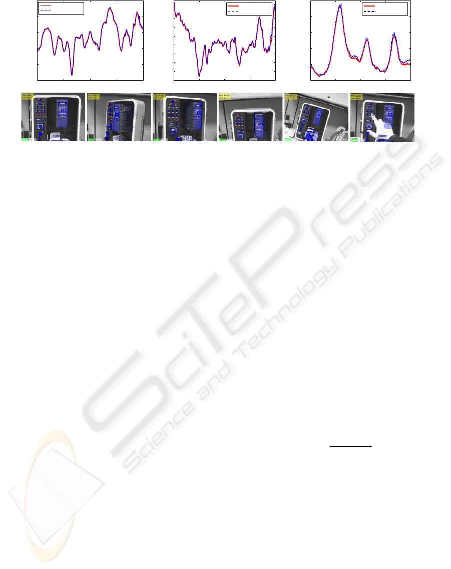
Figure 1: Comparison of pose estimation results against ground truth.The solid red line in each plot represents the true value
of the three coordinates of the camera position and the dashed blue line depicts the estimated one by our detection algorithm
for each frame of a long sequence which includes strong viewpoint and scale changes as well as occlusions (bottom row).
et al., 2002), can be used for further local geometric
constraints.
In the case of using RDTs for classification, the
estimated pose can further be used to update the de-
cision Trees to the actual viewing conditions at run-
time (Boffy et al., 2006). Our experiments showed
that this can significantly improve the matching per-
formance and makes it more robust to illumination
changes, such as cast shadows or reflections.
In our experiments the RDT-based classification
has been shown to have slightly better classification
rate than the PCA-based one. Our non-optimized im-
plementation needs about 200 ms for the PCA based
and 120 for RDT-based approach. To evaluate the
robustness and accuracy of our detection system we
used long sequences taken from a control panel. Each
frame was then used separately as input image to
detect and estimate the pose of the panel. Fig. 1
depicts the pose estimation results compared to the
ground truth data created by tracking the object using
RealViz
tm
software. The median error in camera po-
sition is about 2.0 cm and about 10 degrees in camera
rotation.
4 VISUAL TRACKING
4.1 Theoretical Background
In general, the CAD models used in the industry
are stored as polygon meshes that consist in sets of
vertices and polygons defining the 3D shape of the
objects. These meshes are made of simple convex
polygons and, in most of the industrial 3D models,
they are made of triangles. Consequently, it is le-
gitimate to consider that the image contains the pro-
jection of a piecewise-planar environment since ev-
ery triangular face defines a plane. For each plane
in the scene, there exists a (3×3) homography ma-
trix G that links the coordinates p of a certain point
in a reference image I
∗
to its corresponding point q
in the current image I . We suppose that the “im-
age constancy assumption” is verified, i.e., after an
image intensity normalization (that makes the images
insensitive to linear illumination changes), we have:
I
∗
(p) = I (q). The homography matrix is defined
up to a scale factor. In order to fix the scale, we choose
det(G) = 1. Let w(G) : R
2
→ R
2
be the coordinate
transformation (a warping) such that: q = w(G)(p).
The camera displacement between two views can be
represented by a (4×4) matrix T ∈ SE(3) (the Spe-
cial Euclidean group): T =
R t
0 1
, where R is
the rotation matrix and t is the translation vector of
the camera between the two views. The 2D projec-
tive transformation G is similar to a matrix H that
depends on T: G(T) = KH(T)K
−1
, where K is the
upper triangular matrix containing the camera intrin-
sic parameters. The matrix H(T) can be written as:
H(T) =
R + tn
∗>
/
3
√
1 + t
>
Rn
∗
, where n
∗
is the
normal vector to the plane and kn
∗
k = d
∗
where d
∗
is the distance of the plane to the origin of the ref-
erence frame. Now, let A
i
, with i ∈ {1,...,6}, be a
basis of the Lie algebra se(3) (the Lie algebra associ-
ated to the Lie Group SE(3)). Any matrix A ∈ se(3)
can be written as a linear combination of the matri-
ces A
i
: A(x) =
∑
6
i=1
x
i
A
i
, where x = [x
1
, ..., x
6
]
>
and x
i
is the i-th element of the base field. The ex-
ponential map links the Lie algebra to the Lie Group:
exp : se(3) → SE(3). Consequently, a homography
matrix H is a function of T that can be locally param-
eterized as: H(T(x)) = H (exp(A(x))).
REAL-TIME OBJECT DETECTION AND TRACKING FOR INDUSTRIAL APPLICATIONS
341

4.2 Problem Statement
Let q = nm be the total number of pixels in some im-
age region corresponding to the projection of a planar
patch of the scene in the image I
∗
. This image region
is called the reference template. To track the template
in the current image I is to find the transformation
T ∈ SE(3) that warps a pixel of that region in the im-
age I
∗
into its correspondent in the image I , i.e.
find T such that ∀i, we have: I
w
G(T)
(p
i
)
=
I
∗
(p
i
). For each plane in the scene, we consider its
corresponding template and its homography. Here,
for the sake of simplicity, we describe the compu-
tations for a single plane. Knowing an approxima-
tion
b
T of the transformation T, the problem is to find
the incremental transformation T(x) such that the dif-
ference between the current image region I warped
with
b
TT(x) and the reference image I
∗
is null, i.e.
∀i ∈ {1, ..., q}: y
i
(x) = I
w(G(
b
TT(x)))(p
i
)
−
I
∗
(p
i
) = 0. Let y(x) be the (q ×1) vector contain-
ing the image differences: y(x) = [y
1
(x), ..., y
q
(x)]
>
.
Then, the problem consists of estimating x =
e
x veri-
fying the system:
y(
e
x) = 0 (2)
The system is then non linear and needs to be solved
iteratively.
4.3 The ESM Algorithm
Let J(x) be the (q ×6) Jacobian matrix describing the
variation of the vector y(x) with respect to the Carte-
sian transformation parameters x. Let M(x
1
,x
2
) be
the (q ×6) matrix that verifies ∀(x
1
,x
2
) ∈ R
6
×R
6
:
M(x
1
,x
2
) = ∇
x
1
(J(x
1
)x
2
). The Taylor series of y(x)
about x =
e
x can be written:
y(
e
x) ≈ y(0) +
J(0) +
1
2
M(0,
e
x)
e
x = 0 (3)
Although the optimization problem can be solved
using 1st-order methods, we use an efficient 2nd-
order minimization algorithm (Benhimane and Malis,
2006). Indeed, with little extra computation, it is
possible to perform a stable and local quadratic con-
vergence when the 2nd-order approximation is ver-
ified: for x =
e
x, the system (2) can then be writ-
ten: y(
e
x) ≈ y(0) +
1
2
(J(
e
x) + J(0))
e
x = 0. The update
e
x of the 2nd-order minimization algorithm can then
be computed as follows:
e
x = −2(J(0) + J(
e
x))
+
y(0).
Thanks to the simultaneous use of the reference and
the current image derivatives, and thanks to the Lie al-
gebra parameterization, the ESM algorithm improves
the convergence frequency and the convergence rate
of the standard 1st-order algorithms (see (Benhimane
and Malis, 2006) for more details).
4.4 Tracking Multiple Faces and
Speeding up the System
In the formulation of the ESM algorithm, it is implic-
itly assumed that all reference faces come from the
same image and they were extracted in the same co-
ordinate system. However, this is not true in prac-
tice since two faces can be seen for the first time un-
der different poses. This problem is solved by intro-
ducing the pose
e
T
j
under which the face j was ex-
tracted the first time into the algorithm. This leads to
a different system from the one described in equation
(2) and it becomes:
∑
j
y
j
(
e
x) = 0 where y
j
(x) is the
(q
j
×1) vector containing the image differences of the
face j: y
j
(x) = [y
j1
(x), ..., y
jq
j
(x)]
>
and ∀i ∈ [1,q
j
]:
y
ji
= I
w
G
b
TT(x)
e
T
−1
j
(p
i
)
−I
∗
(p
i
). This
modification makes it possible to add templates in the
tracking process as soon as they become visible by the
camera at any time of the image sequence.
In order to speed up the tracking process, the tem-
plates are reduced a few times in size by a factor of
two to create a stack of templates at different scales.
The optimization starts at the highest scale level (low-
est resolution) and the cost function is minimized on
this level until convergence is achieved or until the
maximum number of iterations has been exceeded.
If the optimization converges before the maximum
number of iterations has been reached it is restarted
on the next scale level with the pose estimated on the
previous level. This is continued until the lowest scale
level (highest resolution) is reached or the maximum
number of iterations is exceeded.
5 TEMPLATE MANAGEMENT
5.1 Simplifying the 3D Model
The ESM algorithm can be used to track any indus-
trial object since every model can be described by a
set of triangular faces (each face defining a plane).
However, the number of the faces grows very quickly
with the model complexity. For instance, the model
shown in Figure 2(a) is described by a mesh of more
than 20,000 faces while the number of planes that
can be used for the tracking process is much smaller.
In addition, given the camera position, the visibility
check of the faces can not be processed in real-time.
VISAPP 2008 - International Conference on Computer Vision Theory and Applications
342
For these reasons, we transform the original CAD
model in order to simplify the triangulated mesh, so
that the largest connected faces are obtained as poly-
gons. This procedure reduces the amount of faces to
work on by around 75% in our examples.
5.2 Building the BSP Trees
Using the simplified model, we construct a 3D Bi-
nary Space Partioning tree (BSP tree) that allows to
determine the visible surfaces of the considered ob-
ject given the camera position. The BSP tree is static,
image size invariant and it depends uniquely on the
3D model so it can be processed off-line once and
for all. The processing time for building a BSP tree
is fast since it is just O(N), where N is the num-
ber of faces in the model. For more details about
BSP trees, refer to (Foley et al., 1990; Schneider and
Eberly, 2002). From any relative position between the
camera and the object, the visible faces can be auto-
matically determined. In fact, the BSP tree is used
to determine the order of all faces of the model with
respect to the optical axis toward the camera. Back-
faces and too small faces are discarded because they
do not provide usable information to the tracking pro-
cess. From the z-ordered sequence of faces, we obtain
a list of those, which are not occluded by others. Once
a face is determined to be occluded, it has never to be
checked again, so even if the worst case of this occlu-
sion culling is O(N
2
), the amortized cost are supposed
to be around O(N), although this was not proved.
To deal with partial occlusions a face is consid-
ered to be occluded, if more than 5% of its area is
occluded by other faces. This calculation is done by
2D polygon intersection test. This task is done using
2D BSP trees, which makes it possible to determine
the intersection in just O(E1 + E2), where E1 and E2
are the number of edges of the two faces to intersect.
5.3 Template Update and Database
Management
The automatic extraction of the trackable faces leads
to the question, whether this can be done during the
tracking procedure to update the faces and increase
the number of the images that can be tracked from the
reference images without any update. The naive ap-
proach to re-extract the faces leads to error integration
and severe drifts. To prevent this, we used a two-step
approach. First, when a face j
1
is seen for the first
time, it will be stored in a Database. For each face
exists two templates. The one in the Database (called
reference template), referring to the first time of ex-
traction and the current one, referring to the last time
of extraction. The face is first tracked with the current
template which leads to a camera pose parameters x
1
.
Then, it is tracked with the reference template start-
ing at x
1
which leads to camera pose parameters x
2
.
The second step is to examine the difference in cam-
era motion kx
1
−x
2
k. If it is below a given threshold,
the reference template in the Database is updated by
the current one (see (Matthews et al., 2003) for more
details). The procedure of determining visible faces
and updating the templates are done every 0.5 second.
Their processing time is about 40ms. Therefore, one
image has to be dropped (if the acquisition framerate
is 25 fps).
6 EXPERIMENTAL RESULTS
In this paragraph, we describe experimental results
showing the result of the selected detection and track-
ing algorithms. The experiments are done in a real
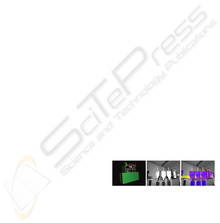
industrial scenario (see Figure 2). Given the CAD
model of an industrial machine (see Figure 2(a)) and
few calibrated images (see Figure 2(b)), the objective
is to estimate the pose of a HMD camera worn by
a worker and observing the scene in real-time. This
makes it possible to overlay virtual objects contain-
ing useful information into the scene in order to help
the training and the maintenance processes for the
workers. In this experiment, we overlay a colored 3D
model of the object (see Figure 2(c)). The acquisition
framerate is at 25 frames per second, and the image
dimensions are (640×480). The object used is poor
in texture and composed of a material with non Lam-
bertian surfaces (and therefore highly sensitive to the
lightening conditions). It shows the benefit of the se-
lected approaches and the intrinsic robustness of the
algorithms to the illumination changes.
(a) The 3D model (b) The keyframe (c) The overlay
Figure 2: The industrial machine. See text.
The method proposed in this paper allows to handle
big interframe displacements and permits to overlay
more accurately the CAD model of the machine on
the acquired images along the whole sequence. In the
Figure 3, despite the lack of texture on the considered
object, we can see that the camera pose has been accu-
rately estimated, even when very few parts are visible.
Thanks to the fast convergence rate and to the high
REAL-TIME OBJECT DETECTION AND TRACKING FOR INDUSTRIAL APPLICATIONS
343
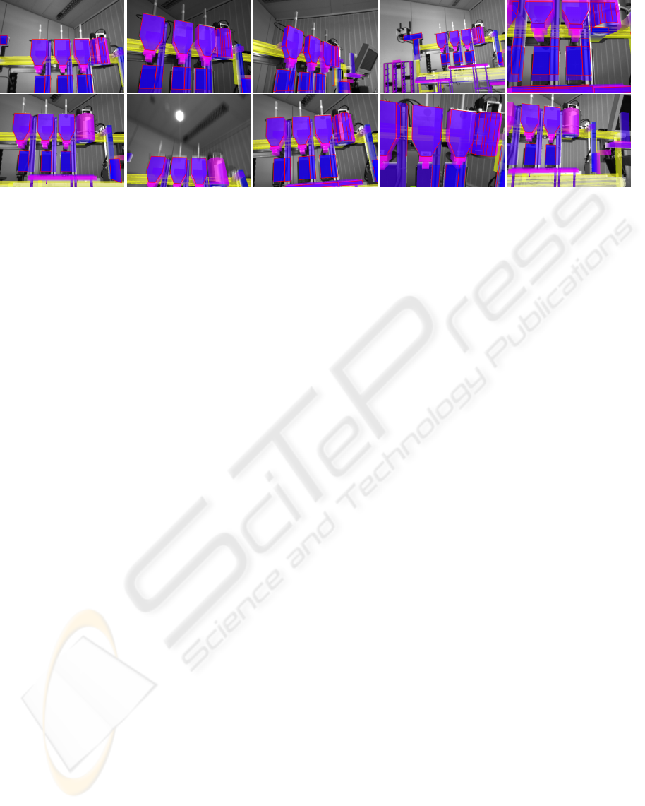
Figure 3: Excerpts from the test sequence showing the result of the tracking system proposed and the quality of the augmen-
tation achieved. The trackable regions selected by the template management algorithm are the ones with red borders.
convergence frequency of the 2nd-order minimiza-
tion algorithm and to thanks to template manage-
ment algorithm, the augmentation task is correctly
performed. Thanks to the tracking initialization that
was invoked each time the object was out of the cam-
era field of view, the pose estimation given by the
complete system was possible each time that the ob-
ject is in the image and it was precise enough to nicely
augment the observed scene with virtual information
(see the video provided as additional material).
7 CONCLUSIONS
Real-time 3D tracking of complex machines in indus-
trial environments has been shown to be a challenging
task. While frame-based tracking systems can achieve
high precision using temporal continuity constraints
they need an initialization and usually suffer from ro-
bustness against occlusions, motion blur and abrupt
camera motions. On the other side object detec-
tion systems using wide baseline matching techniques
tend to be robust but not accurate and fast enough for
real-time applications. This paper presents a fully au-
tomated system to overcome these problems by com-
bining a real-time tracking system with a fast object
detection system for automatic initialization. This al-
lows us to get robustness from object detection, and
at the same time accuracy from recursive tracking.
For the automatic initialization, we build a scalable
and compact representation of the object of interest
during a training phase based on statistical learning
techniques, in order to achieve speed and reliability at
run-time by imposing both geometric and photomet-
ric consistency constraints. Furthermore, we propose
a tracking approach along with a novel template man-
agement algorithm which makes it more scalable and
applicable to complex objects under severe illumina-
tion conditions. Experimental results showed that the
system is able to successfully detect and accurately
track industrial machines in real-time.
REFERENCES
Baker, S. and Matthews, I. (2004). Lucas-kanade 20 years
on: a unifying framework. IJCV, 56(3):221–255.
Baker, S., Patil, R., Cheung, K., and Matthews, I. (2004).
Lucas-kanade 20 years on: Part 5. Technical Report
CMU-RI-TR-04-64, Robotics Institute, CMU.
Bay, H., Tuytelaars, T., and Van Gool, L. J. (2006). Surf:
Speeded up robust features. In ECCV, pages 404–417.
Belongie, S., Malik, J., and Puzicha, J. (2002). Shape
matching and object recognition using shape contexts.
PAMI, 24(4):509–522.
Benhimane, S. and Malis, E. (2006). Integration of eu-
clidean constraints in template-based visual tracking
of piecewise-planar scenes. In IROS, pages 1218–
1223.
Boffy, A., Tsin, Y., and Genc, Y. (2006). Real-time fea-
ture matching using adaptive and spatially distributed
classification trees. In BMVC.
Buenaposada, J. and Baumela, L. (2002). Real-time track-
ing and estimation of planar pose. In ICPR.
Cobzas, D. and Jagersand, M. (2004). 3D SSD tracking
from uncalibrated video. In Proc. of Spatial Coher-
ence for Visual Motion Analysis, in conjunction with
ECCV.
Comaniciu, D. and Meer, P. (2002). Mean shift: A ro-
bust approach toward feature space analysis. PAMI,
24(5):603–619.
Foley, J. D., van Dam, A., Feiner, S. K., and Hughes, J. F.
(1990). Computer graphics: principles and practice.
Addison-Wesley Longman Publishing Co., Inc.
Hager, G. and Belhumeur, P. (1998). Efficient region track-
ing with parametric models of geometry and illumina-
tion. PAMI, 20(10):1025–1039.
Ke, Y. and Sukthankar, R. (2004). PCA-SIFT: a more dis-
tinctive representation for local image descriptors. In
CVPR, pages 506–513.
VISAPP 2008 - International Conference on Computer Vision Theory and Applications
344

Lepetit, V. and Fua, P. (2006). Keypoint recognition using
randomized trees. PAMI, 28(9):1465–1479.
Li, Y., Tsin, Y., Genc, Y., and Kanade, T. (2005). Object de-
tection using 2d spatial ordering constraints. In CVPR.
Lowe, D. (2004). Distinctive image features from scale-
invariant keypoints. IJCV, 60(2):91–110.
Matas, J., Chum, O., Urban, M., and Pajdla, T. (2002). Ro-
bust wide baseline stereo from maximally stable ex-
tremal regions. In BMVC.
Matthews, I., Ishikawa, T., and Baker, S. (2003). The tem-
plate update problem. In BMVC.
Mikolajczyk, K. and Schmid, C. (2004). Scale and affine
invariant interest point detectors. IJCV, 60(1):63–86.
Mikolajczyk, K. and Schmid, C. (2005). A performance
evaluation of local descriptors. PAMI, 27(10).
Mikolajczyk, K., Tuytelaars, T., Schmid, C., Zisserman,
A. C., Matas, J., Schaffalitzky, F., Kadir, T., and
Van Gool, L. (2005). A comparison of affine region
detectors. IJCV, 65(1-2):43–72.
Najafi, H., Genc, Y., and Navab, N. (2006). Fusion of 3D
and appearance models for fast object detection and
pose estimation. In ACCV, pages 415–426.
Schneider, P. J. and Eberly, D. (2002). Geometric Tools for
Computer Graphics. Elsevier Science Inc.
Sepp, W. and Hirzinger, G. (2003). Real-time texture-based
3-d tracking. In DAGM Symposium, pages 330–337.
Tuytelaars, T. and Van Gool, L. (2004). Matching widely
separated views based on affine invariant regions.
IJCV, 59(1):61–85.
REAL-TIME OBJECT DETECTION AND TRACKING FOR INDUSTRIAL APPLICATIONS
345
