
IMPLEMENTATION OF REAL-TIME VISUAL TRACKING
SYSTEM FOR AIRBORNE TARGETS
Muhammad Asif Memon, Furqan Muhammad Khan, Farrukh H. Khan, Rana Muhammad Anees
Instrumentation Division,Pakistan Space and Upper Atmosphere Research Commission (SUPARCO), Gulzar Hijri
Karachi, Pakistan
Omair Abdul Rahman
Department of Electrical Engineering, University of Southern California, LA, USA
Keywords: Visual tracking, histogram, Digital Signal Processing (DSP), track gate, servo control.
Abstract: A real-time visual tracking system is presented for tracking airborne targets. The algorithm is based on
intensity difference between background and the target in a gray-scale frame. As the background is uniform
for videos of airborne targets, decision is made on contrast between tracking gate boundary and the target
inside that rectangular gate. The algorithm is embedded on DSP Starter Kit (DSK) 6713 and a 586
embedded controller is used for servo control and processing. A personal computer (PC) provides the user
interface for the system. The performance of the system is verified with different airborne targets from birds
to helicopters and its reliability and constraints are presented.
1 INTRODUCTION
The field of computer vision has matured to an
extent that not only allows to research on individual
system components and methods but also building
fully integrated systems (Schiele and Sagerer, 2003).
Different tracking algorithms have been proposed
over the years focusing on different problems. Every
algorithm proposed is for a specific application with
constraints and assumptions made according to that
particular application. A lot of work has been done
in visual tracking applications for robotic vision,
human tracking, surveillance and other civilian and
defence applications (Ribaric, et al., 2004).
Depending upon the type of application,
different parameters have been used as reference for
tracking including intensity, colour, motion etc. For
the robotic vision applicaions particle filtering
(Morelande and Challa, 2005; Mihaylova, et al.,
2007), mean shift (Comaniciu, et al., 2000
) and other
algoithms have been proposed. Applications
involving tracking objects from airborne platform
are of importance in video monitoring and
surviellance and because of complex background
conditions, motion detection and tracking is more
suitable (Cohen and Medioni, 1998).
An application of surviellance, monitoring, and
range instrumentation is to track airborne targets
from ground based platforms. A simple tracking
algorithm is required to reduce the complexity of the
system and to provide robust performance for this
type of applications. In this scenario, complex
algorithms are not required as the background is
uniform for airborne targets except for the cloudy
conditions. Hence, simple intensity based algorithm
can be used for segregating the target from the
background. Classifiers trained on the basis of
intensities to distinguish between the target and the
background are used by (Avidan, 2007). In order to
achieve high speed tracknig performance, the
ensemble approach of (Avidan, 2007) is simplified
to classification of pixels as background or target on
frame to frame basis instead of training classifier
based on search rectangles. This can be achieved as
the background does not change considerably in
successive frames for aerial videos and small strips
taken around the track gate can be used to represent
the background. For high-speed real-time
performance, Digital Signal Processors (DSPs) have
been used in visual tracking as well as other
applications (Boni, et al., 1996; Gemignani, et al.,
1999).
635
Asif Memon M., Muhammad Khan F., H. Khan F., Muhammad Anees R. and Abdul Rahman O. (2008).
IMPLEMENTATION OF REAL-TIME VISUAL TRACKING SYSTEM FOR AIRBORNE TARGETS.
In Proceedings of the Third International Conference on Computer Vision Theory and Applications, pages 635-640
DOI: 10.5220/0001074606350640
Copyright
c
SciTePress
A real-time visual tracking system using
contrast between target and background for air borne
targets has been implemented for application in
range instrumentation. High speed DSP has been
used for image processing alongwith 586 embedded
controller for servo control of the tracking mount
equiped with optical imaging equipment for video
capture.
2 REAL-TIME VISUAL
TRACKING SYSTEM
A detailed description of each module and the
algorithm for the real-time visual tracking system
will be given followed by the experimental results
and discussion on the performance of the system.
2.1 System Architecture
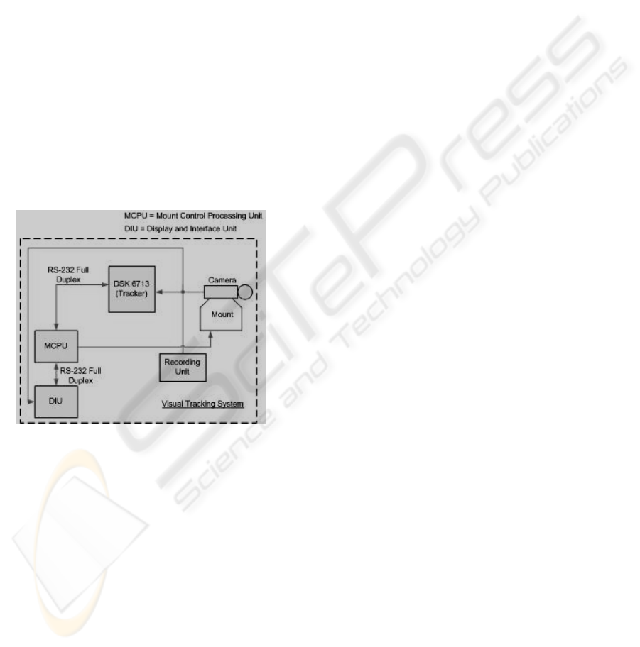
The simplified block diagram of the system is
depicted in Figure 1.
Figure 1: Block Diagram of the visual tracking system.
There are three blocks performing different tasks:
A personal computer is used as Display and
Interface Unit (DIU) to provide a user friendly
interface as well as display the tracking video.
TMS 320C6713 DSP Starter Kit (DSK) is
used along with a video daughter card to grab
the video frames for image processing and
provide real-time target location to the MCPU
and DIU for update and display.
An Intel 586 processor based engine is used as
Mount Control and Processing Unit (MCPU)
to transform the tracking error in pixels from
the DSP into angular displacement and to
position the tracking mount accordingly.
2.2 Tracking Algorithm
The tracking algorithm used in the system is based
on rejecting the background from a certain region of
interest to highlight the target. This is achieved by
manually placing a track-gate around the target to
specify the region of interest. The boundaries of the
track-gate are processed and the corresponding
intensity values are marked as the background
region. A histogram of the intensities for the region
inside the track-gate is made and everything inside
the track-gate that has an intensity level different
from the range of background intensities is
nominated as the target.
As the algorithm is based on the intensity
values of the target; therefore, the iris level of the
tracking camera should be adjusted to provide high
contrast between the target and the background. The
initial acquisition is performed by the DIU, where
the user clicks on the target such that it is inside the
track-gate region identified by the white rectangle on
the screen.
2.3 Display and Interface Unit
The user interface of the system is designed in
Visual Basic (VB) 6.0. A video card is used to
capture video in parallel with the DSP kit. The user
interface is used to display the real-time video with
track gate, the azimuth and elevation feedbacks from
the MCPU, and the location of target in pixels from
the DSK.
As the DIU is implemented in windows based
environment, the track gate is placed by clicking on
the video using mouse. The actual video size used
for processing in DSK is ‘352x288’ pixels from
Common Interchange Format (CIF). However, for
better display the video is scaled by a constant
multiplier (3 for this system). When the user clicks
on the target for initial acquisition, the location of
the target is communicated to the DSK and upon
receipt of an acknowledgement the track gate turns
green to indicate that a lock is obtained. The DSK
continually sends the gate target location in pixels to
the DIU at a rate of 25 packets per second in
conformance with 25 frames/seconds for PAL
standard.
Apart from updating gate location, the DIU also
provides the facility to change the tracking
parameters. The track-gate size can also be adjusted
depending upon the size of the target being tracked
by using the arrow keys of the keyboard. Seven
different gate sizes supported by the system are
given in Table 1.
VISAPP 2008 - International Conference on Computer Vision Theory and Applications
636
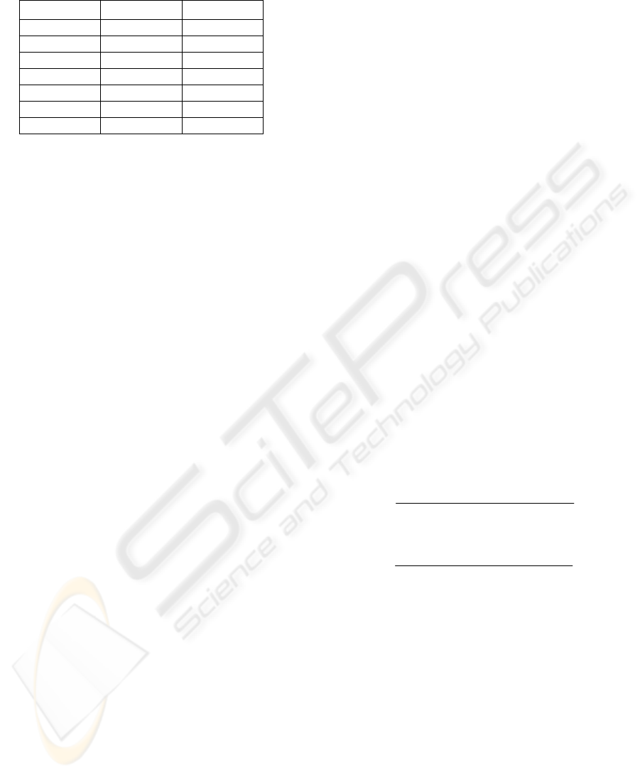
Table 1: List of gate sizes with their corresponding
identification codes.
Gate size X (pixels) Y (Pixels)
0 24 20
1 32 32
2 64 32
3 64 64
4 128 64
5 128 128
6 256 128
The location of the target in pixels is received
every 40ms from the DSK and is updated on the
labels for X and Y axis. The azimuth and elevation
values for the mount are also received from the
MCPU at the same rate and are displayed on the
corresponding label boxes.
2.4 Image Processing using DSK 6713
The tracking algorithm used in this system is
embedded in the DSK board. Texas Instruments®
(TI) TMS 320C6713 DSK board is used for high
speed processing and communication. DSK board
has been selected to facilitate the up gradation of the
tracking algorithm as per requirement in future
without much hardware modifications. As the video
input/output facility is not available on the DSK
board, a third party video daughter card is used for
frame capture. The DSK uses the tracking algorithm
to calculate the target position in pixels and
communicates it to MCPU which relays the packet
to DIU. Both the modules update their position
accordingly i.e. the DIU updates the track-gate on
display, while the MCPU calculates the error
between the current and required mount positions
and drives the servo to centre the target on screen.
2.4.1 Frame Capture and Background
Calculation
The video signal from the camera in PAL format is
applied to the analogue video input of the daughter
card. The video grabbed by the daughter board is
converted into 4:2:2 format of CIF standard with a
resolution of 352x288 pixels. Once a frame has been
captured by the daughter card, an interrupt is
generated to the processor which uses the Enhanced
Direct Memory Access (EDMA) channel to load the
frame. The communication between the daughter
card and the DSK is carried out by high-speed
Multi-Channel Buffered Serial Port (McBSP) of the
DSK 6713. The second serial port is used as
Universal Asynchronous Receiver/Transmitter
(UART) for communication between the DSK and
other modules of the system.
The region of interest initialised by the user on
DIU is extracted from the frame and the gate
boundaries are processed within 8 pixels to be
labelled as background. The intensity values labelled
as background are used as a reference to separate the
target within the gate from the background.
2.4.2 Histogram Formation and Spatial
Model
The gray-scale pixel values from 0 to 255 are
initialised as memory locations of an array to
represent the histogram. All pixels that fall within
background have a value of ‘0’. The region inside
the track-gate is processed and membership function
ψ
target
(x, y) given in Equation 1 is used to determine
whether the pixel (x, y) belongs to target.
otherwise
YyxY
yx
Background
ett
∉
⎩
⎨
⎧
=
),(
0
1
),(
arg
ψ
(1)
Where, Y(x, y) represent the intensity of the
pixel (x, y) and Y
Background
represents the pixel
intensity marked as a member of background region.
The spatial location of the pixels within target
as provided by the membership function is used to
calculate the centre of the target. The mean location
of the target (x
target
, y
target
) at the time instant k is
calculated as (Memon, et al., 2006),
,
),(
),(
arg),(
arg),(
arg
∑
∑
∈
∈
=
iiettRyx
iiettiRyx
ett
yx
yxx
x
ii
ii
ψ
ψ
,
),(
),(
arg),(
arg),(
arg
∑
∑
∈
∈
=
iiettRyx
iiettiRyx
ett
yx
yxy
y
ii
ii
ψ
ψ
(2)
Where R denotes the search area of the target.
2.4.3 Gate Update and Tracking Speed
The default gate-size is 64x64 pixels, which can be
changed by the user in real-time. The DSK updates
the target location and communicates the location to
the DIU. The DIU uses the received word to
calculate the new gate location and updates that on
the screen. The target lock condition is maintained
as long as the DSK sends the target location with
appropriate lock code in command byte of the
packet (Section 2.6). If the number of pixels within
the target drops below a threshold, 2 pixels in our
system, the unlock command is initiated by the DSK
IMPLEMENTATION OF REAL-TIME VISUAL TRACKING SYSTEM FOR AIRBORNE TARGETS
637
for both the DIU and the MCPU and the track gate
on the DIU turns red to notify the user about unlock.
The unlock command can also be generated by the
user by using the right click of mouse anywhere on
the screen. In this case, the DIU generates the unlock
command to DSK and the MCPU to halt the tracker.
The video standard of PAL has a frame rate of
25 frames per second and the tracking algorithm is
required to perform its calculation within 40
milliseconds. However, the algorithm being simple
and efficient takes much lesser time than this. The
maximum frame rate supported by the daughter card
is 30 frames per second and the algorithm is tested
to work reliably at this speed.
2.5 Mount Control and Processing Unit
The third module of the system is the mount control
unit which takes location of the target from the DSK
and transforms that into angular displacement
required to bring the target to the crosshair, or the
centre of the screen. The tracking mount used is the
Kineto tracking mount with maximum speed of 60
degrees per seconds in both elevation and azimuth
axis. The servo drive for the mount is controlled
through a modified Proportional-Integral-Derivative
(PID) controller. The controller takes the angular
feedback from Resolver-to-Digital Converter (RDC)
in binary format with accuracy up to three decimal
places in degrees. This angular information is used
to minimise the error between actual and the
required mount position and is also transferred to
DIU for display.
The Intel 586 based embedded controller with
daughter card for serial interface and Analogue-to-
Digital Converters (ADCs) has been used for mount
control and processing. Apart from the servo
controller, the 586 engine is used to take joystick
inputs through ADC to drive the mount manually to
bring the target in the camera field of view for initial
acquisition. Further, the controller works as a hub
for serial communication between the DSK tracker
and the DIU as illustrated in Figure 1.
2.6 Communication Protocol and
Packet Description
One of the most critical issues in system design is to
select and implement the communication protocol
for data transfer between the three modules. The
communication between the three modules is carried
out using RS-232 standard at a baud rate of
38.4Kbps. A custom data packet format has been
used for all the communications. The packet used
contains eight bytes as shown in Figure 2.
Figure 2: Data packet format for communication between
the three modules.
The first two bytes contain the header to mark
the beginning of valid data. The second byte
contains the action code for the DIU or DSK as
required. Next four bytes contain the parameters to
be used based on the action code received. Finally,
the last byte contains the checksum byte containing
sum of all bytes for error detection.
Table 2: Details of action codes and their corresponding
parameter bytes.
Action
Code
Purpose Useful Parameter
Bytes
0 Lock Command
(From DIU)
4B Æ GateX (2B)
GateY (2B)
1 Object Position
(From DSK)
4B Æ X Coord (2B)
Y Coord (2B)
2-3 Reserved for
Zoom request
RESERVED
4 Gate Size
Change (From
DIU)
1B Æ Gate Select
Code (See Table 1)
5 Unlock
command (DIU
or DSK)
0 Byte (0B)
6 Algorithm Select
(Reserved for
future)
1B Æ Value
0 = Intensity based
1 = Reserved
2 = Reserved
7 RESERVED RESERVED
The details of action code and corresponding
parameter bytes are given in Table 2. All code
values are not used in the system and three bits are
reserved for future advancements.
2.7 Camera Calibration
Different camera calibration schemes have been
proposed over the years for single (Hsu and Aquino,
1999) as well as multiple cameras (Everts, et al.,
2006), specially for applications in robot vision
systems (Corke and Hutchinson, 2000). Recently,
VISAPP 2008 - International Conference on Computer Vision Theory and Applications
638
self camera calibration schemes have also been
introduced to deal with the situations where variable
zoom camera is used and no feedback is available
for focal length (Li and Shen, 2006).
It has been suggested (Corke and Hutchinson,
2000) that the camera calibration required by robot
vision systems is not needed for many applications
and simple calibration techniques involving pixel
size and focal length can be used for vertical and
horizontal angular displacements (Shiao, 2001). If
the camera focal length is known, as in this case,
Equation 3 can be used to calculate the pan and tilt
angles from displacement in pixels.
⎟
⎟
⎠
⎞
⎜
⎜
⎝
⎛
Δ+
=
−
f
ttd
xx
x
)(
tan
1
ε
θ
⎟
⎟
⎠
⎞
⎜
⎜
⎝
⎛
Δ+
=
−
f
ttd
yy
y
)(
tan
1
ε
θ
(3)
Where, f stands for focal length, ε represents
pixel length and d
x
and d
y
represent the error in
pixels for x and y- axis respectively.
Equation 3 has been verified using field-of-
view of the camera in use and the resolution of the
camera by taking different points as reference and
moving the mount to get the angular displacement
for the predefined pixel displacements. In the case of
variable focal length camera, the feedback of the
focal length is available via potentiometers, so there
is no need for self calibration and same calibration
method is used.
3 EXPERIMENTAL RESULTS
As the communication protocol is uniform for all
communications, initially, only DSK tracker and
DIU were used to verify the reliability of the
algorithm and its constraints. After initial testing, the
MCPU was also interfaced and the loop was
completed with MCPU connected with servo drive
and feedback.
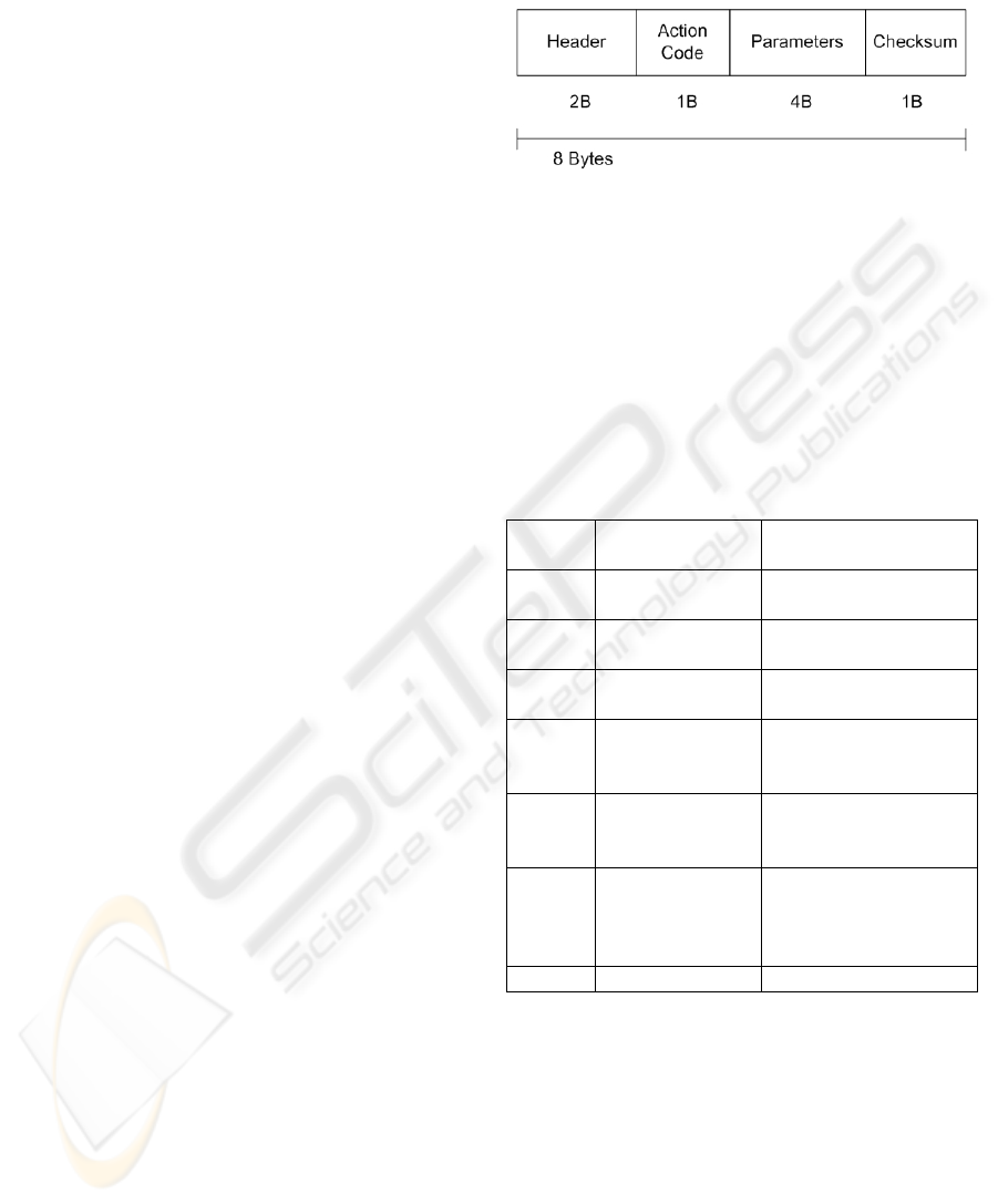
Figure 3: Snapshot of the dummy target being tracked by
the system.
As the system is designed for airborne targets
with assumption of uniform background within track
gate, a dummy target was fabricated with a black
patch in the centre of a white board. The system was
tested on the dummy target with user initialising the
tracking system by clicking on the dummy target.
The system was able to track the target successfully
in stationary as well as moving scenario. The
snapshot of the video while the moving dummy
target was being tracked is shown in Figure 3.
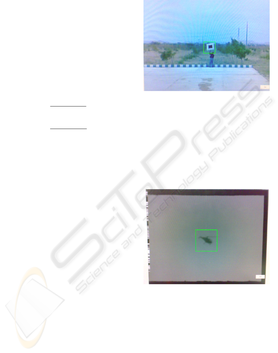
Figure 4: Snapshot of a helicopter being tracked by the
system.
The next step was to track a real airborne target
with the system. A number of commercial airlines
and helicopters were tracked during this practice.
For appropriate contrast conditions (Section 2.2) set
by camera opening, the system was able to track the
flying targets reliably. Different gate sizes were
changed in real-time and it was verified that the
system maintains the lock while shifting from one
gate size to other. However, if the gate size is much
larger than the target size, considerable jitters are
added to tracking because of large search area as
IMPLEMENTATION OF REAL-TIME VISUAL TRACKING SYSTEM FOR AIRBORNE TARGETS
639

compared to the target size. Airborne targets of any
speed can be tracked as long as the object does not
cover a distance equal to half the track-gate size in
successive frames. A snapshot of a helicopter being
tracked by the system is given in Figure 4.
Apart from maintaining lock for different gate
sizes, the system was also verified to keep the target
locked while changing zoom during tracking. As the
algorithm uses target and background intensities, it
loses lock when the background and the target are
very close in intensity i.e. lighting conditions are not
good. Further, if there is more than one target in the
gate, the system will follow the target with more
contrast with the background.
4 CONCLUSIONS
A real-time visual tracking system using gray-scale
video is implemented for the specific application of
tracking airborne targets. The system is designed to
identify the target within a track gate, initialised by
the user, by rejecting the background extracted from
gate boundaries. The system is tested with different
airborne targets and speeds and is able to maintain
lock on the target provided the required lighting
conditions are maintained and the target does not
move more than half the gate size between two
successive frames. Further, provisions have been
provided for future advancements in the system for
adding auto-zoom function and algorithm selection
for different tracking scenarios.
Future research will be oriented to add motion
cue to aid the intensity based tracking system and to
improve the algorithm to adapt with different
surrounding conditions.
ACKNOWLEDGEMENTS
This work was supported and funded by
Instrumentation division of Pakistan Space and
Upper atmosphere Research Commission
(SUPARCO). We wish to thank our colleagues and
higher authorities for their support and cooperation
during the project.
REFERENCES
Avidan, S., (2007). Ensemble Tracking. IEEE
Transactions on Pattern Analysis and Machine
Intelligence, 29(2):261-271
Boni, A., Dolce, A., Rovetta, S., Zunino, R., (1996). A
Neural Networks Based Visual Tracking System. In
International Workshop on Neural Networks for
Identification, Control, Robotics, and Signal/Image
Processing (NICROSP '96), pages 128-135, Italy.
Cohen, I., and Medioni, G., (1998) Detecting and tracking
moving objects in video from and airborne observer.
In Proc. IEEE Image Understanding Workshop, pages
217--222.
Comaniciu, D., Ramesh, D., Meer, P., (2000). Real-Time
Tracking of Non-Rigid Objects Using Mean Shift, in
Proc. of 1
st
Conf. Comp. Vision Pattern Recognition,
2:142-149.
Corke, P., Hutchinson, S., (2000). Real-Time Vision,
Tracking and Control. In Proceedings of ICRA 2000,
pages 622-629
Everts, I., Sebe, N., Jones, G., (2007) Cooperative Object
Tracking with Multiple PTZ Cameras, International
Conference on Image Analysis and Processing,
Modena, Italy (to be published).
Gemignani, V., Provvedi, S., Demi, M., Paterni, M.,
Benassi, A., (1999). A DSP-Based Real Time Contour
Tracking System, in Proceedings of the 10th
International Conference on Image Analysis and
Processing, pages 630-635, Italy.
Hsu, L., Aquino, P.L.S., (1999). Adaptive visual tracking
with uncertain manipulator dynamics and uncalibrated
camera, In Proceedings of the 38th IEEE Conference
on Decision and Control, 1999. 2:1248-1253.
Li, H., Shen, C., (2006). An LMI Approach for Reliable
PTZ Camera Self-Calibration. IEEE International
Conference on Video and Signal Based Surveillance,
2006. AVSS '06. pages 79-84.
Memon, M.A., Angelov, P., and Ahmed, H., (2006). An
Approach to Real-time Color-based Object Tracking.
In 2006 International Symposium on Evolving Fuzzy
Systems, pages 82-87, UK.
Mihaylova, L., Brasnett, P., Canagarajah N., and Bull, D.,
(2007). Object Tracking by Particle Filtering
Techniques in Video Sequences, in Advances and
Challenges in Multisensor Data and Information
Processing, Vol. 8, NATO Security Through Science
Series: Information and Communication Security, E.
Lefebvre (Ed.), IOS Press, pages 260-268, the
Netherlands.
Morelande, M.R., Challa, S., (2005). Manoeuvring target
tracking in clutter using particle filters, IEEE
Transactions on Aerospace and Electronic Systems,
41(1):252 – 270.
Ribaric, S., Adrinek, G., and Segvic, S., (2004). Real-time
active visual tracking system, in Proceedings of the
12th IEEE Mediterranean Electrotechnical
Conference, pages 231-234, Dubrovnik, Croatia.
Schiele, B., and Sagerer, G., (2003). editorial: Computer
vision systems, International Journal of Machine
Vision and Applications, 14:3-4.
Shiao Y-S., (2001). Design and implementation of real-
time tracking system based on vision servo control.
Tamkang Journal of Science and Engineering. 4
(1):45-58.
VISAPP 2008 - International Conference on Computer Vision Theory and Applications
640
