HARMONIC DEFORMATION MODEL FOR EDGE BASED
TEMPLATE MATCHING
Andreas Hofhauser
Technische Universit
¨
at M
¨
unchen, Boltzmannstr. 3, 85748 Garching b. M
¨
unchen, Germany
Carsten Steger
MVTec Software GmbH, Neherstr. 1, 81675 M
¨
unchen, Germany
Nassir Navab
Technische Universit
¨
at M
¨
unchen, Boltzmannstr. 3, 85748 Garching b. M
¨
unchen, Germany
Keywords:
Deformable Template Matching, Pattern Recognition in Image Understanding, Object recognition.
Abstract:
The paper presents an approach to the detection of deformable objects in single images. To this end we
propose a robust match metric that preserves the relative edge point neighborhood, but allows significant
shape changes. Similar metrics have been used for the detection of rigid objects (Olson and Huttenlocher,
1997; Steger, 2002). To the best of our knowledge this adaptation to deformable objects is new. In addition,
we present a fast algorithm for model deformation. In contrast to the widely used thin-plate spline (Bookstein,
1989; Donato and Belongie, 2002), it is efficient even for several thousand points. For arbitrary deformations,
a forward-backward interpolation scheme is utilized. It is based on harmonic inpainting, i.e. it regularizes the
displacement in order to obtain smooth deformations. Similar to optical flow, we obtain a dense deformation
field, though the template contains only a sparse set of model points. Using a coarse-to-fine representation
for the distortion of the template further increases efficiency. We show in a number of experiments that the
presented approach in not only fast, but also very robust in detecting deformable objects.
1 INTRODUCTION
The fast, robust, and accurate localization of a given
2D object template in images has been a research
topic for many decades. The results of these ef-
forts have enabled numerous different applications,
because the detection of the pose of an object is the
natural prerequisite for any useful operation. If the
object is deformable, not only the pose, but also the
deformation of the object must be determined simul-
taneously. Extracting this information allows to un-
warp the found region in the image and facilitates
OCR or a comparison with a prototype image for, e.g.,
detection of possible manufacturing errors. Various
application domains, which necessitate the detection
of deformable objects, can still not be comprehen-
sively solved. This is due to the fact that on the one
hand conventional pose estimation algorithms, like
generalized Hough transform or template matching,
do not allow the object to alter its shape nonlinearly.
On the other hand, descriptor-based methods notori-
ously fail if the image contains not enough or only a
small set of repetitive texture like in figure 1.
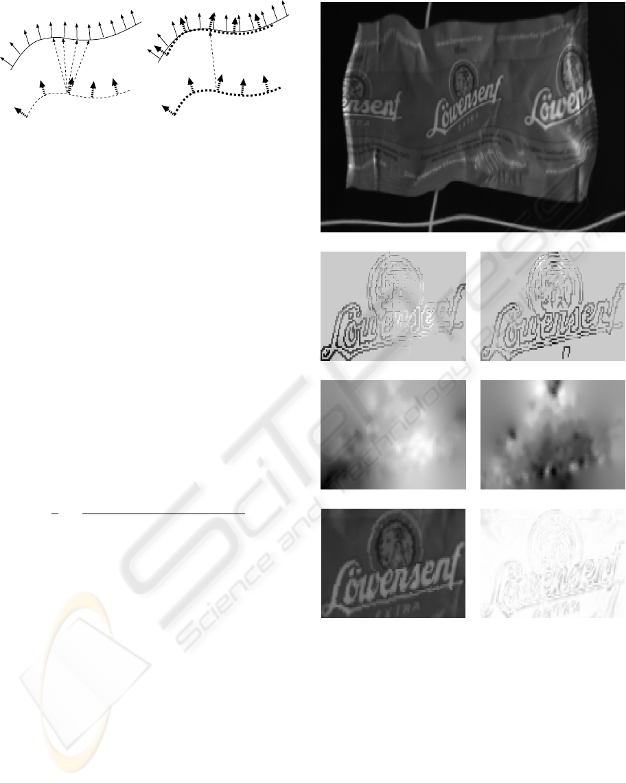
Figure 1: Two images of a deformed logo. The detected
deformed model is overlaid in white. The detection works
robustly even though the object contains only repetitive pat-
terns.
1.1 Related Work
We roughly classify algorithms for pose detection into
template matching and descriptor-based methods. In
75
Hofhauser A., Steger C. and Navab N. (2008).
HARMONIC DEFORMATION MODEL FOR EDGE BASED TEMPLATE MATCHING.
In Proceedings of the Third International Conference on Computer Vision Theory and Applications, pages 75-82
DOI: 10.5220/0001071800750082
Copyright
c
SciTePress

the descriptor-based category, the rough scheme is to
first determine discriminative “high level” features,
extract from these feature points surrounding discrim-
inative descriptors, and to establish correspondence
between model and search image by classifying the
descriptors. The big advantage of this scheme is that
the runtime of the algorithm is independent of the de-
gree of the geometric search space. Recent prominent
examples, which fall into this category, are (Belongie
et al., 2002; Lowe, 2004; Berg et al., 2005; Pilet et al.,
2005; Bay et al., 2006). While showing outstanding
performance in several scenarios, they fail if the ob-
ject has only highly repetitive texture or only sparse
edge information. The feature descriptors overlap in
the feature space and are not discriminating anymore.
In the template matching category, we subsume algo-
rithms that perform an explicit search. Here, a simi-
larity measure that is either based on intensities (like
SAD, SSD, NCC and mutual information) or gradi-
ent features is evaluated. Using intensities is popular
in optical flow estimation and medical image registra-
tion, where a rough overlap of source and target image
is assumed (Horn and Schunck, 1981; Modersitzki,
2004). However, the evaluation of intensity-based
metrics is computationally expensive. Additionally,
they are typically not invariant against nonlinear illu-
mination changes, clutter, or occlusion.
For the case of feature-based template matching, only
a sparse set of features between template and search
image is compared. While extremely fast and ro-
bust if the object undergoes only rigid transforma-
tions, these methods become intractable for a large
number of degrees of freedom, e.g. when an ob-
ject is allowed to deform perspectively or arbitrar-
ily. Nevertheless, one approach for feature-based de-
formable template matching is presented in (Gavrila
and Philomin, 1999), where the final template is cho-
sen from a learning set while the match metric is eval-
uated. Because obtaining a learning set and applying
a learning step is problematic for many scenarios, we
prefer to not rely on training data except for the origi-
nal template. Another approach is to use a template
like (Felzenszwalb, 2003) or (Zhang et al., 2004).
Here an adapting triangulated polygon model is rep-
resenting the outer contour. Unlike this representa-
tion, our model is a set of edge points allowing us to
express arbitrarily shaped objects e.g. curved or com-
posite objects. In (Jain et al., 1996) and (Gonzales-
Linares et al., 2003) a deformable template model is
adapted while tracking object hypotheses down the
image pyramid. Here, for each match candidate a
global deformation field represented by trigonometric
basis functions is optimized. Unfortunately, this rep-
resentation of the deformations is global, so that small
adaptations in one patch of the model propagate to all
areas, even where the object remains rigid. In contrast
to this, we preserve local neighborhood, and therefore
do not encounter this problem. However, we note that
these works are the closest approaches to ours and in-
spired us in several ways.
1.2 Main Contributions
This paper makes the following contributions: The
first contribution is a deformable match metric that al-
lows for local deformations, while preserving robust-
ness to illumination changes, partial occlusion and
clutter. While we found a match metric with normal-
ized directed edge points in (Olson and Huttenlocher,
1997; Steger, 2002) for rigid object detection, and
also for articulated object detection in (Ulrich et al.,
2002), its adaptation to deformable object detection
is new.
The second contribution is an efficient deformation
model, allowing a dense unwarping, even though the
template contains only a sparse set of points. There-
fore, we first propagate the deformation into regions
between the points and then back-propagate these de-
formations into the original model. Hence, we ob-
tain a reprojected smooth displacement field from
the original deformation. The proposed forward-
backward harmonic inpainting does not have the
problems of folding typically encountered with the
popular thin-plate splines (TPS) (Bookstein, 1989).
Additionally, the manipulation of our model only de-
pends on the size of the enclosing rectangle, but not
on the number of model points. To the best of our
knowledge these appealing properties have not yet
been exploited in the field of deformable object de-
tection.
2 DEFORMABLE SHAPE-BASED
MATCHING
In the following, we detail the deformable shape-
based model generation and matching algorithm. The
problem that this algorithm solves is particularly dif-
ficult, as in contrast to optical flow, tracking, or med-
ical registration, we assume neither temporal nor lo-
cal coherence. While the location of deformable ob-
jects is determined with the robustness of a template
matching method, we avoid the necessity of expand-
ing the full search space as if it was a descriptor-based
method.
VISAPP 2008 - International Conference on Computer Vision Theory and Applications
76

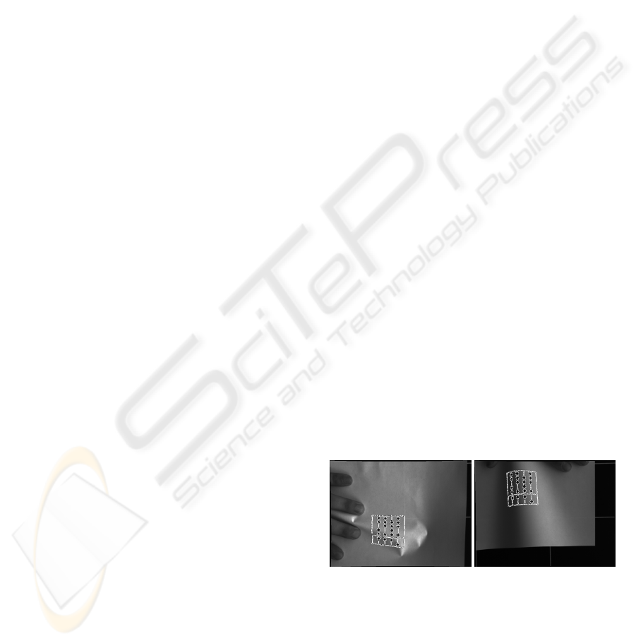
Figure 2: In the top image the rectangular white ROI de-
fines the template. The bottom image depicts the extracted
neighborhood graph of the model.
2.1 Shape Model Generation
As mentioned in section 1.1, we want our model to
represent arbitrary objects. For the generation of our
model, we decided to rely on the result of a simple
contour edge detection. This allows as to represent
objects from template images as long as there is any
intensity change. Note that in contrast to corners or
other point features, we can model objects that con-
tain only curved contours. Furthermore, directly gen-
erating a model from an untextured CAD format is
in principle possible. For all descriptor based ap-
proaches, a manual alignment between template im-
ages that show the texture and the CAD model would
be required. Therefore, our shape model M
rig
is com-
posed as an unordered set of edge points
M
rig
=
r
i
, c
i
, d
m
i
, n
i1
, . . . , n
ik
|i = 1 . . . n
(1)
Here, r and c are the row and column coordinates of
the model points. d
m
denotes the normalized gradi-
ent direction vector at the respective row and column
coordinate of the template. At model generation, we
index for every model point the nearest k model points
n
i1
, . . . , n
ik
. This allows us to access them efficiently
at runtime. As the model generation is completely
learning-free and the calculation of the neighborhood
graph is realized efficiently, this step needs, even for
models with thousands of points, less than a second.
One example of this model generation by setting a re-
gion of interest and the extracted neighborhood graph
is depicted in figure 2.
2.2 Deformable Metric based on Local
Edge Patches
Given the generated M
rig
, the task of the deformable
matching algorithm is to extract instances of the
model in new images. As mentioned in section 1.2,
we therefore adapted the match metric of (Steger,
2002). This score function is designed such that it
is inherently invariant against nonlinear illumination
changes, partial occlusion and clutter. The score func-
tion for rigid objects reads as follows:
s(r, c) =
1
n
n
∑
i=1
hd
m
i
, d
s
(r+r
i
,c+c
i
)
i
kd
m
i
k · kd
s
(r+r
i
,c+c
i
)
k
(2)
where d
s
is the direction vector in the search image,
h·i is the dot product and k · k is the Euclidean norm.
Three observations are important: First, the point set
of the model is compared to a dense gradient direction
field of the search image. Even with significant non-
linear illumination changes that propagate to the gra-
dient amplitude the gradient direction stays the same.
Furthermore, a hysteresis threshold or non maximum
suppression is completely avoided resulting in true in-
variance against arbitrary illumination changes. Sec-
ond, partial occlusion, noise, and clutter results in ran-
dom gradient directions in the search image. These
effects lower the maximum of the score function but
do not alter its location. Hence, the semantic mean-
ing of the score value is the ratio of matching model
points. Third, comparing the cosine between the gra-
dients leads to the same result, but calculating this
formula with dot products is several orders of mag-
nitudes faster.
To extend this metric for deformable object detec-
tion, we instantiate globally only similarity transfor-
mations. By allowing successive local deformations,
we implicitly evaluate a much higher class of non-
linear transformations. Following this argument, we
distinguish between an explicit global score function
s
g
, which is evaluated for, e.g. similarity, and a local
implicit score function s
l
, that allows for local defor-
mations. Similar to the rigid case, the global score
function s
g
is a sum over all the model points local
contributions. If the model is partially occluded, only
this ratio of all the model points change.
s
g
(r, c) =
1
n
n
∑
i=1
s
l
(r, c, i) (3)
One observation that is important for designing the
local score function is depicted in figure 3. If we
allow the model points to deform independently, the
gradient direction is not discriminative anymore. Fur-
thermore, if we allow a point to deform with a rota-
tion its local score value gives us a match for all po-
sitions. Even if we prevent rotations from occurring,
HARMONIC DEFORMATION MODEL FOR EDGE BASED TEMPLATE MATCHING
77
Independent Model Gradients
Image Gradients
Ambiguity
Gradients with Neighbors
No Ambiguity
Image Gradients
Figure 3: In the left image, each model point is considered
independently. This results in displacements that are highly
ambiguous. As depicted in the right picture, taking the local
neighborhood into account allows to resolve this ambiguity.
the ambiguity, particularly along edge contours, is not
resolved. With clutter or noise it is essential that the
model can be discriminated from the background or
from similar objects.
As a remedy, we add rigidity constrains that take the
movement and location of neighborhood points into
account. We assume that even after deformation the
neighborhood of each model point stays the same and
is approximated by a local euclidean transformation.
Hence, we instantiate local euclidean transformations
T
l
for each point and apply it on the local neighbor-
hood. The local score then is the maximum alignment
of gradient direction between the locally transformed
model points and the search image. Accordingly, the
proposed local score functions s
l
is:
s
l
(r, c, i) =
max
T
l
1
k
k
∑
j=1
hT
l
(d
m
n
i j
), d
s
(r+T
l
(r
n
i j
),c+T
l
(c
n
i j
))
i
kd
m
n
i j
k · kd
s
(r+T
l
(r
n
i j
),c+T
l
(c
n
i j
))
k
(4)
For the sake of efficiency, we exploit the neighbor-
hood graph that was generated in the offline phase for
accessing the neighboring points (the n
i j
matrix). Fur-
thermore, we cache T
l
(d
m
n
i j
), T
l
(r
n
i j
) and T
l
(c
n
i j
) since
they are independent of r and c.
2.3 Deformable Shape Matching
After defining an efficient score function that toler-
ates local deformations, we integrated it into a gen-
eral purpose object detection system. We decided to
alter the conventional template matching algorithm
such that it copes with deformed objects. Hence, the
deformable shape matching algorithm first extracts
an image pyramid of incrementally zoomed versions
of the original search image. At the highest pyra-
mid level, only the rough location of the model is
determined. To speed up this exhaustive search the
evaluation of the score function can be transparently
restricted in our implementation to relevant search
(a)
(b) (c)
(d) (e)
(f)
(g)
Figure 4: In (a) a part of a search image deformed by a
random TPS-transformation is depicted. The images in (b)
and (c) show the displacements at model points with re-
spect to row and column coordinates. A medium gray value
means no deformation, brighter gray values denote positive,
dark negative displacements. As depicted in (d) and (e), we
obtain a smooth deformation after forward-backward har-
monic inpainting. The image (f) contains the unwarped
image region. The inverted difference image between un-
warped and original model area is shown in (g). We observe
only a small difference that is due to sampling effects.
regions or to a restricted amount of rotation/scale
ranges. The rough location resides at the local max-
VISAPP 2008 - International Conference on Computer Vision Theory and Applications
78

ima of the score s
g
function (3). This initial set of
candidates are further refined until either the lowest
pyramid level is reached or no match candidates are
above a certain score value. While tracking the can-
didates down the pyramid, a rough deformation was
already extracted during evaluation of the current can-
didate’s parent on a higher pyramid level. Therefore,
we first use the deformation originating from the can-
didate’s parent to warp the model up to the known
deformation. Now, starting from this deformed can-
didate the deformation is iteratively refined by evalu-
ating only the local score function with (4). Here, we
keep the best displacements T
l
and reproject the can-
didate given the deformation model that we discuss
later in section 2.4. As a result of these local iterative
refinements, we obtain the best instance of the model
with respect to the score function and the deformation
model. This deformed candidate is defined as:
M
de f
= {r, c, M
rig
, dr
i
, dc
i
} (5)
Here, r, c is the pose and dr
i
, dc
i
denote a displace-
ment vector that brings each model point from the
rigid to the deformed position. Hence, we known the
exact displacements only at locations where there are
model points.
However, for two reasons we need to infer defor-
mations for positions, that we do not know from
measurements. First, when we propagate deforma-
tions between pyramid levels, contour segments of
our model exist only at certain pyramid levels. Hence,
we bring the model that is deformed to the pyramid
level of the source deformation. Then we apply the
deformation and bring the model back to the original
scale. Second, when we finally unwarp the detected
image region, we have to interpolate deformation at
image regions where there are no model points.
For the rigid planar case of a perspective deforma-
tion, we estimate the parameters of a homography
by the well-known normalized DLT algorithm. This
parametrized warp is applied in a straightforward
way. As we think that this is not new, we do not
discuss this case further. However, for arbitrary de-
formations one need a suitable model.
2.4 Harmonic Deformation Model
Because no a priori information is known about the
exact physical behavior of our objects, we need a gen-
eral deformation model. This model is used for prop-
agating the deformation down the image pyramid and
to unwarp found instances (see section 2.3). Even
though we know the exact displacements at model
points, we expect it to give outliers, because no metric
is resistant to occasional failure. Preliminary experi-
ments with the widely used Thin Plate Spline model,
where we interpret model points as landmarks, failed.
The main problem is to suppress crossings of the
moving landmarks, leading to foldings. Particularly
problematic are the cases, where different landmark
points end up at exactly the same point or when two
nearby points move into different directions. Even
with the best local match metric, it is hardly possible
to suppress this entirely. Therefore, we take different
measures for e.g. preventing foldings due to outliers.
As a first step we insert M
de f
into a row and column
deformation image. Hence, only pixels, where model
points are located, are set. One example for an in-
serted row/column deformation is shown in figure 4
(b) and 4 (c). In the next step, we infer the deforma-
tion of areas that are not lying at model points (The
medium gray pixels of the deformation images). We
state this task as an inpainting problem where the non-
model region is regarded as destroyed pixels and must
be interpolated. The reconstruction that we use solves
the discrete Laplace equation,
u
xx
+ u
yy
= 0 (6)
for the corresponding pixel value u that originates
from the deformation vector dr
i
and dc
i
. This particu-
lar inpainting function can be decomposed into inde-
pendent row and column coordinates allowing an ef-
ficient solution by a gradient decent solver. This is re-
ferred as harmonic interpolation in the image restora-
tion literature (Aubert and Kornprobst, 2006). In the
original region discontinuities and crossing are still
present. Therefore, after we have extrapolated the
gray values, we apply the inpainting on the inverse
(original) model region. Hence, the original point dis-
placements are only approximated. This implicitly re-
solves the problem of crossings of landmark move-
ments that are encountered along contours. While
harmonic inpainting gives reasonable results only for
small regions (because, e.g., edges or texture is lost),
in our application it generates the desired deformation
field (see image 4 (d) and (e)). It strongly penalizes
abrupt changes in the model. Furthermore, it smooths
out small errors of the detection that are encountered
frequently e.g. along contours.
3 EXPERIMENTS
For evaluation of the robustness of the proposed ob-
ject detection algorithm we conducted experiments
under synthetic and real world conditions. Under sim-
ulated conditions we independently measure the influ-
ence of the proposed score function in section 3.1 and
the deformation model in section 3.2.
HARMONIC DEFORMATION MODEL FOR EDGE BASED TEMPLATE MATCHING
79
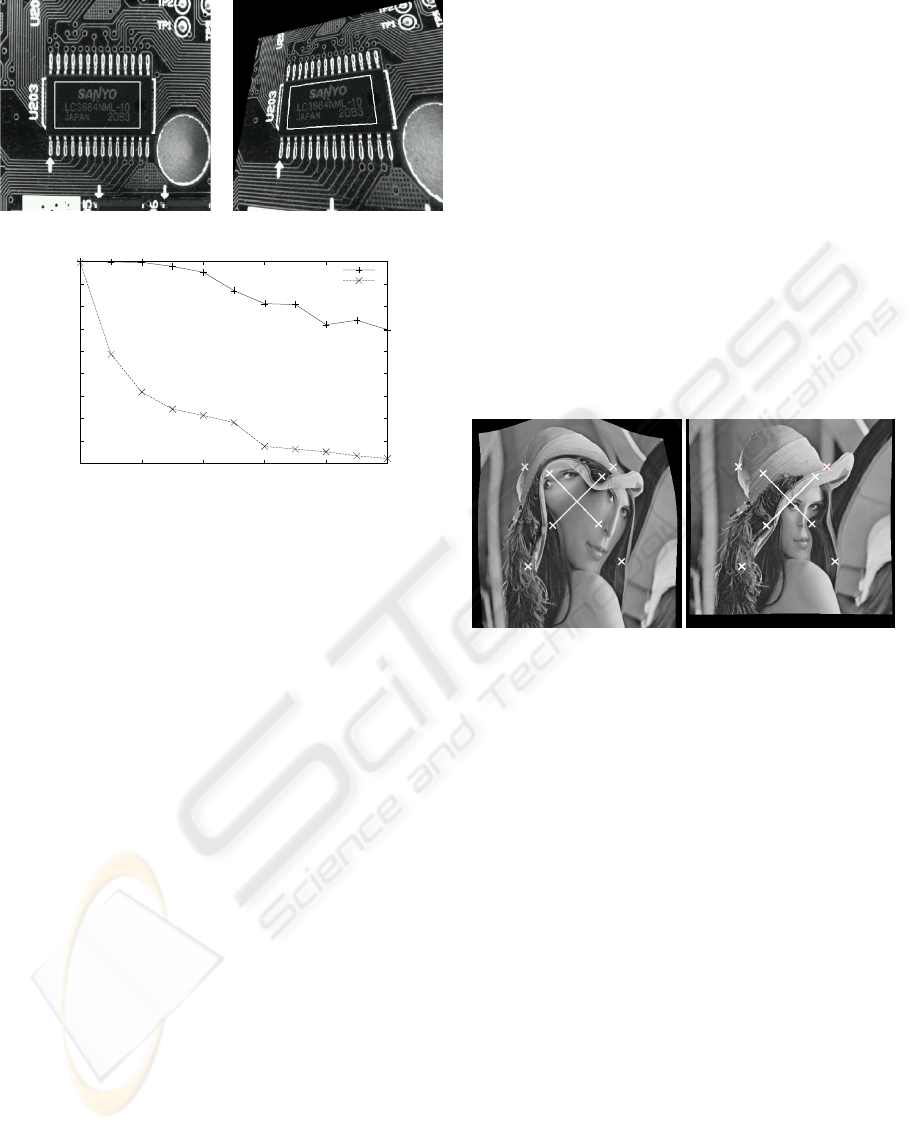
(a) (b)
0.1
0.2
0.3
0.4
0.5
0.6
0.7
0.8
0.9
1
0 2 4 6 8 10
Recognition Percentage
Pixel Random Displacement
Recognition Example Industrial Image
Shape-based
Descriptor-based
Figure 5: Synthetic experiments: In the picture (a) the orig-
inal template image is depicted. The region of interest is
overlaid in white. In (b) a perspectively distorted test im-
age is shown. The detected template is denoted with the
white rectangle. In the bottom the results of the detection
experiments is plotted.
3.1 Comparison with Descriptor-Based
Matching
In order to compare the proposed method with state
of the art detection algorithms, we decided in a first
step to restrict the deformation to a perspective dis-
tortion. Hence, the simulated model remains rigid and
only the robustness of the detection is measured, not
the underlying deformation model. Here we are par-
ticularly interested to compare the proposed method
with a descriptor-based approach. We choose (Lep-
etit et al., 2005), as it is known for its robustness even
in the presence of big perspective changes. There-
fore, we generate homographies by random move-
ments of the corner points of the rectangle that de-
fine the model. These displacements define a per-
spective distortion that we apply onto the original im-
age (see figure 5 (a) for original and (b) for distorted
image). Both the shape matching and the descriptor-
based approach try to extract a homography from this
image. For (Lepetit et al., 2005) we choose 25 trees
of depth 11, favoring robustness instead of speed. For
each size of the movement we generated 500 ran-
dom views. We tested different images with differ-
ent textured content. For highly textured objects the
proposed method only slightly outperforms (Lepetit
et al., 2005). However, we observe a significant dif-
ference in objects like in figure 5. The robustness of
the descriptor-based method decreases rapidly even
for small displacements. In contrast to this, the pro-
posed method is robust despite increasing distortions.
This is mainly due to the fact that the repetitive struc-
tures (like the leads at the chip) pose a problem for the
descriptor-based method. Furthermore, we observe
that extracting edges is superior to interest points not
only in terms of robustness but also accuracy.
3.2 Simulated Tps and Harmonic
Deformation
Figure 6: Simulated Deformations: On the left image with
TPS deformation and on the right with the harmonic defor-
mation model. The landmark correspondences are shown
with the source/target points as white crosses.
For testing reasons we generated various synthetic de-
formations with the TPS and our proposed harmonic
model. In figure 6 the behavior for an exemplary re-
sult of the two models under artificial displacements
is depicted. This artificial displacement is defined by
six landmark points. The four that are at the corners
of a quadrilateral are static and two that are inside this
quadrilateral move away such that their path crosses.
These crossings could originate from mismatches as
discussed in section 2.4. Hence, the crossing of
the landmark points induce a non-diffeomorphic dis-
placement. Under the TPS model the image is dis-
torted in an unnatural way. By penalizing the TPS
deformation parameters except the affine transforma-
tion (see (Bookstein, 1989)), we hoped to solve this
problem. Unfortunately, it is difficult to adjust the
regularizing parameter and control this kind of shape
change. A further observation is that a global defor-
mation is extrapolated outside the area of the land-
marks. In contrast to this, the forward-backward har-
monic deformation model is parameter free and does
VISAPP 2008 - International Conference on Computer Vision Theory and Applications
80
not fold. It only bends the image locally according
the displacements. Also, only a translation is extrap-
olated globally, but not the nonlinear shape change.
We admit that this is a totally artificial example, but
the robustness of a deformation model with respect to
outliers play a crucial role when a detection system
is constructed that must handle complex models auto-
matically.
Another important observation is that the proposed
harmonic deformation model is an order of magni-
tude faster than the TPS deformation. The reason for
this is that the computational complexity for our har-
monic deformation model is linear in the size of the
deformation field that is to be inpainted. Furthermore,
it is independent of the number of landmark points. In
contrast to this, the complexity of calculating the TPS
is cubic with the size of the model points and there-
fore becomes intractable for large-scale models like
the one we use. However, efficient approximations
for TPS functions are still target of current research
(see, e.g., (Donato and Belongie, 2002)). While this
difference cannot be noticed for a small amount of
landmark points (for less than 10 landmarks the TPS
is even faster), the difference is dramatic for large
models. If we take typical example images like fig-
ure 4 (a), the calculation of the TPS parameters and
unwarping takes several minutes. With the harmonic
inpainting this is calculated in ms.
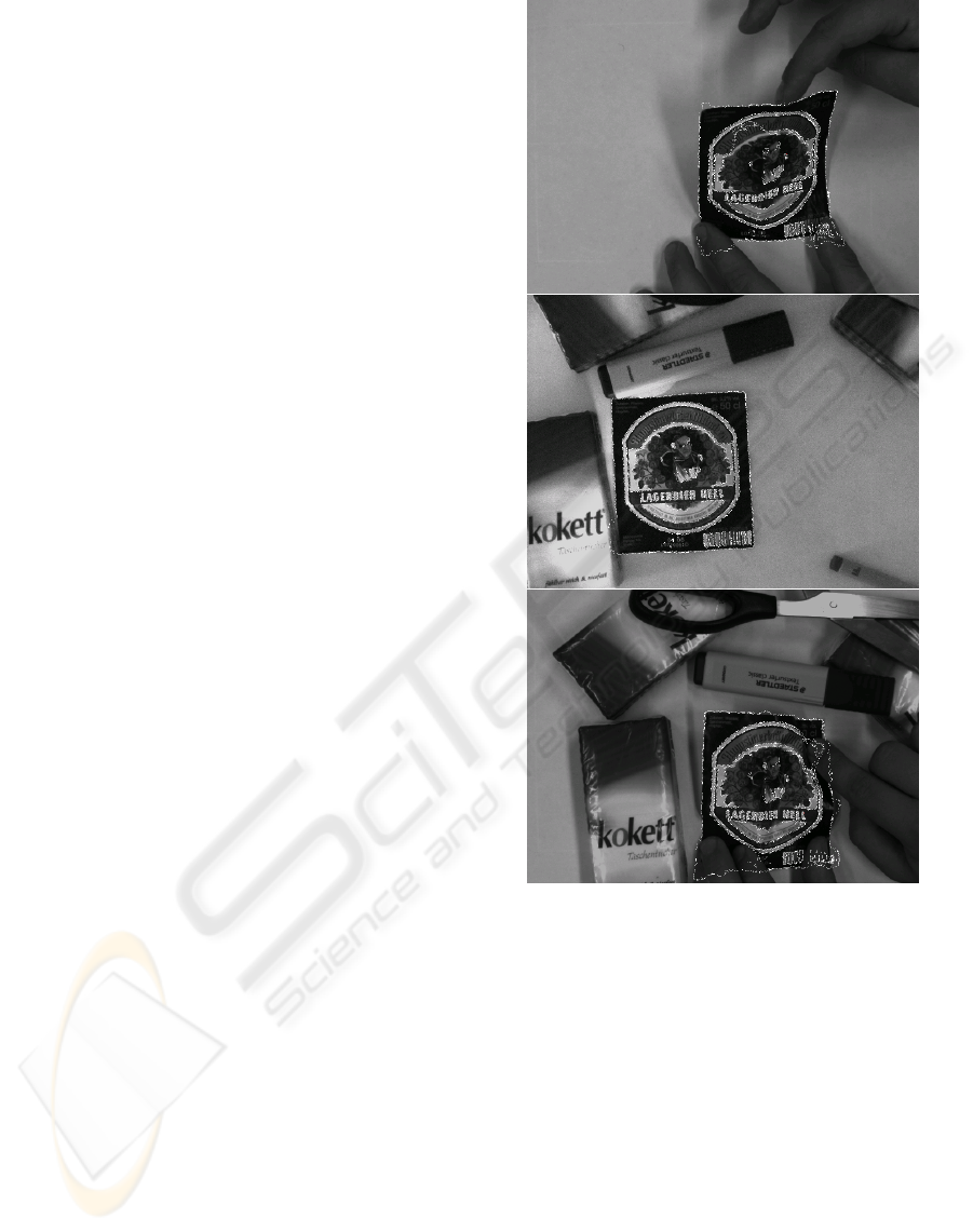
3.3 Real World Experiments
The proposed object detection algorithm was tested
on real sequences. Sample frames are depicted in
figure 7. The object to be found is deformed, par-
tially occluded, and illuminated in changing ways.
After detection, we overlay the original image with
the model. Despite the different adverse conditions
the object is found globally with high robustness. One
remaining problem is that in case of partial occlusion
we currently don’t distinguish between deformation
and occlusion. Furthermore, some model parts tend to
match with nearby edges of the same polarity. Even
though this is not a problem for the global detection,
this issue will be addressed in future work. Here, we
expect even better results by adding further regular-
ization conditions to the model. If we instantiate a full
rotation for the model, detection and unwarping takes
typically around 1 second on a desktop computer.
4 CONCLUSIONS
In this paper we presented a solution for deformable
template matching that can be utilized in a wide range
Figure 7: Detection of a deformed object in the presence
of clutter, noise, illumination changes and occlusion. The
video sequence is provided in the supplementary material.
It shows the strength and limitations of our approach.
of applications. For this, we extended an already ex-
isting edge polarity based match metric for tolerat-
ing local shape changes. The proposed deformation
model, which is based on minimizing the Laplacian
of the deformation field, allows a precise unwarping
and enforces smooth displacement fields in an elegant
way.
Future work will be to further reduce the runtime of
the algorithm by an optimized implementation. Addi-
tionally, this deformable shape matching can be used
as a module for compound object detection. While
currently all model points have the same importance,
leading to a split into a local-global match metric, we
HARMONIC DEFORMATION MODEL FOR EDGE BASED TEMPLATE MATCHING
81

plan to introduce a multi-level hierarchical decompo-
sition of our model, such that different layers and dif-
ferent local sub-parts are considered independently.
REFERENCES
Aubert, G. and Kornprobst, P. (2006). Mathematical Prob-
lems in Image Processing: Partial Differential Equa-
tions and the Calculus of Variations (second edi-
tion), volume 147 of Applied Mathematical Sciences.
Springer-Verlag.
Bay, H., Tuytelaars, T., and Gool, L. V. (2006). Surf:
Speeded up robust features. European Conference on
Computer Vision.
Belongie, S., Malik, J., and Puzicha, J. (2002). Shape
matching and object recognition using shape contexts.
IEEE Transactions on Pattern Analysis and Machine
Intelligence, 24(4):509–522.
Berg, A., Berg, T., and Malik, J. (2005). Shape matching
and object recognition using low distortion correspon-
dences. In Conference on Computer Vision and Pat-
tern Recognition, San Diego, CA.
Bookstein, F. L. (1989). Principal warps: Thin plate splines
and the decomposition of deformations. IEEE Trans-
actions on Pattern Analysis and Machine Intelligence,
11:567–585.
Donato, G. and Belongie, S. (2002). Approximate thin plate
spline mappings. European Conference on Computer
Vision, 2:531–542.
Felzenszwalb, P. F. (2003). Representation and detection of
deformable shapes. In Computer Vision and Pattern
Recognition, volume 1, pages 102–108.
Gavrila, D. M. and Philomin, V. (1999). Real-time object
detection for “smart” vehicles. In 7th International
Conference on Computer Vision, volume I, pages 87–
93.
Gonzales-Linares, J., N.Guil, and E.L.Zapata (2003). An
efficient 2d deformable object detection and location
algorithm. In Pattern Recognition, volume 36, pages
2543–2556.
Horn, B. K. P. and Schunck, B. G. (1981). Determining
optical flow. Artifical Intelligence, 17:185–203.
Jain, A. K., Zhong, Y., and Lakshmanan, S. (1996). Object
matching using deformable templates. IEEE Trans-
actions on Pattern Analysis and Machine Intelligence,
18(3):267–278.
Lepetit, V., Lagger, P., and Fua, P. (2005). Randomized
trees for real-time keypoint recognition. In Confer-
ence on Computer Vision and Pattern Recognition,
San Diego, CA.
Lowe, D. G. (2004). Distinctive image features from scale-
invariant keypoints. International Journal of Com-
puter Vision.
Modersitzki, J. (2004). Numerical Methods for Image Reg-
istration. Oxford University Press Series: Numerical
Mathematics and Scientific Computation.
Olson, C. F. and Huttenlocher, D. P. (1997). Automatic
target recognition by matching oriented edge pixels.
IEEE Transactions on Image Processing, 6(1):103–
113.
Pilet, J., Lepetit, V., and Fua, P. (2005). Real-time non-rigid
surface detection. In Conference on Computer Vision
and Pattern Recognition, San Diego, CA.
Steger, C. (2002). Occlusion, clutter, and illumination in-
variant object recognition. In Kalliany, R. and Leberl,
F., editors, International Archives of Photogrammetry,
Remote Sensing, and Spatial Information Sciences,
volume XXXIV, part 3A, pages 345–350, Graz.
Ulrich, M., Baumgartner, A., and Steger, C. (2002). Au-
tomatic hierarchical object decomposition for object
recognition. In International Archives of Photogram-
metry and Remote Sensing, volume XXXIV, part 5,
pages 99–104.
Zhang, J., Collins, R., and Liu, Y. (2004). Representation
and matching of articulated shapes. In Computer Vi-
sion and Pattern Recognition, volume 2, pages 342–
349.
VISAPP 2008 - International Conference on Computer Vision Theory and Applications
82
