
BIO-INSPIRED DATA AND SIGNALS CELLULAR SYSTEMS
Andr´e Stauffer, Daniel Mange and Jo¨el Rossier
Logic Systems Laboratory, Ecole polytechnique f´ed´erale de Lausanne (EPFL), CH-1015 Lausanne, Switzerland
Keywords:
Self-organization, configuration, cloning, cicatrization, regeneration.
Abstract:
Living organisms are endowed with three structural principles: multicellular architecture, cellular division,
and cellular differentiation. Implemented in digital according to these principles, our data and signals cellular
systems present self-organizing mechanisms like configuration, cloning, cicatrization, and regeneration. These
mechanisms are made of simple processes such as growth, load, branching, repair, reset, and kill. The data
processed in the self-organizing mechanisms and the signals triggering their underlying processes constitute
the core of this paper.
1 INTRODUCTION
Borrowing three structural principles (multicellular
architecture, cellular division, and cellular differenti-
ation) from living organisms, we have already shown
how to grow cellular systems thanks to two algo-
rithms: an algorithm for cellular differentiation, based
on coordinate calculation, and an algorithm for cellu-
lar division (Mange et al., 2004). These cellular sys-
tems are endowed with self-organizing properties like
configuration, cloning, cicatrization, and regeneration
(Stauffer et al., 2005).
In a previous work (Stauffer et al., 2006), the
configuration mechanisms (structural and functional
growth), the cloning mechanisms (cellular and organ-
ismic growth), the cicatrization mechanism (cellular
self-repair), and the regeneration mechanism (organ-
ismic self-repair) were already devised as the result of
simple processes like growth, load, branching, repair,
reset, and kill. The goal of this paper is to point out the
data processed in these mechanisms and the signals
triggering their underlying processes. Starting with a
minimal system, a cell made up of six molecules, Sec-
tion 2 will introduce digital simulations to describe
the data and the signals involvedin the self-organizing
mechanisms and the corresponding processes. We de-
fine then a small organism made of three cells, the
“SOS” acronym, as an application example for the
simulation of our mechanisms and processes (Sec-
tion 3). A brief conclusion (Section 4) summarizes
our paper and opens new research avenues.
2 SELF-ORGANIZING
MECHANISMS
2.1 Structural Configuration
The goal of the structural configuration mechanism is
to define the boundaries of the cell as well as the liv-
ing mode or spare mode of its constituting molecules.
This mechanism is made up of a structural growth
process followed by a load process. For a better un-
derstanding of these processes, we apply them to a
minimal system, a cell made up of six molecules ar-
ranged as an array of two rows by three columns, the
third column involving two spare molecules dedicated
to self-repair.
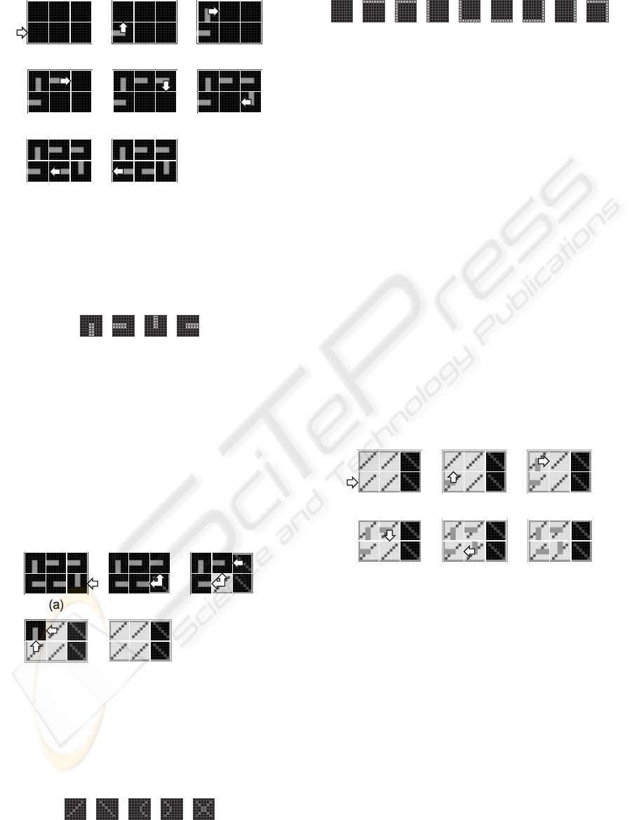
The growth process starts when an externalgrowth
signal is applied to the lower left molecule of the cell
(Fig. 1a) and this molecule selects the corresponding
eastward data input (Fig. 1b). According to the struc-
tural configuration data or structural genome, each
molecule of the cell generates then successively an
internal growth signal and selects an input (Fig. 2),
in order to create a data path among the molecules of
the cell (Fig. 1b-g). When the connection path be-
tween the molecules closes, the lower left molecule
delivers a close signal to the nearest left neighbor cell
(Fig. 1h). The structural configuration data is now
moving around the data path and ready to be trans-
mitted to neighboring cells.
The load process is triggered by the close sig-
nal applied to the lower right molecule of the cell
(Fig. 3a). A load signal propagates then westward
and northward through the cell (Fig. 3b-d) and each of
203
Stauffer A., Mange D. and Rossier J. (2008).
BIO-INSPIRED DATA AND SIGNALS CELLULAR SYSTEMS.
In Proceedings of the First International Conference on Bio-inspired Systems and Signal Processing, pages 203-207
DOI: 10.5220/0001057402030207
Copyright
c
SciTePress
(e)
(f)
(g)
(a)
(b) (c)
(d)
(h)
Figure 1: Structural growth process of a minimal system, a
cell made up of six molecules. (a) External growth signal
is applied to the lower left molecule. (b-g) Generation of
internal growth signals to build the structural data path. (h)
Closed path and close signal delivered to the nearest left
neighbor cell.
(a) (b) (c) (d)
Figure 2: Data input selection. (a) Northward. (b) East-
ward. (c) Southward. (d) Westward.
its molecules acquire a molecular mode (Fig. 4) and
a molecular type (Fig. 5). We finally obtain an homo-
geneous tissue of molecules defining both the bound-
aries of the cell and the position of its living mode and
spare mode molecules (Fig. 3e). This tissue is ready
for being configured by the functional configuration
data.
(b)
(c)
(d)
(e)
Figure 3: Load process. (a) External close signal applied
to the lower right molecule by the nearest right neighbor
cell. (b-e) Generation of internal load signals propagating
westward and northward to store the molecular modes and
types of the cell.
(a) (b) (c) (d)
(e)
Figure 4: Molecular modes. (a) Living. (b) Spare. (c)
Faulty. (d) Repair. (e) Dead.
(b) (c) (d)
(a)
(e) (f)
(g) (h)
(i)
Figure 5: Molecular types. (a) Internal. (b) Top. (c) Top-
left. (d) Left. (e) Bottom-left. (f) Bottom. (g) Bottom-right.
(h) Right. (i) Top-right.
2.2 Functional Configuration
The goal of the functional configuration mechanism
is to store in the homogeneous tissue, which already
contains structural data (Fig. 3e), the functional data
needed by the specifications of the current applica-
tion. This mechanism is a functional growth process,
performed only on the molecules in the living mode
while the molecules in the spare mode are simply by-
passed. It starts with an external growth signal ap-
plied to the lower left living molecule (Fig. 6a). Ac-
cording to the functional configuration data or func-
tional genome, the living molecules then successively
generate an internal growth signal, select an input,
and create a path among the living molecules of the
cell (Fig. 6b-f). The functional configuration data is
now moving around the data path and ready to be
transmitted to neighboring cells.
(a)
(b) (c)
(d)
(e)
(f)
Figure 6: Functional configuration of the cell performed as
a functional growth process applied to the living molecules.
(a) External growth signal is applied to the lower left
molecule. (b-e) Generation of internal growth signals in or-
der to build the functional data path. (f) Closed functional
data path.
2.3 Cloning
The cloning mechanism or self-replication mecha-
nism is implemented at the cellular level in order to
build a multicellular organism and at the organismic
level in order to generate a population of organisms.
This mechanism suppose that there exists a sufficient
number of molecules in the array to contain at least
one copy of the additional cell or of the additional or-
ganism. It corresponds to a branching process which
BIOSIGNALS 2008 - International Conference on Bio-inspired Systems and Signal Processing
204
takes place when the structural and the functionalcon-
figuration mechanisms deliver northward and east-
ward growth signals on the borders of the cell during
the corresponding growth processes (Fig. 7).
(a)
(b) (c)
(d)
Figure 7: Generation of growth signals triggering the
cloning mechanism. (a) Northward structural branching
process. (b) Eastward structural branching process. (c)
Northward functional branching process. (d) Eastward
functional branching process.
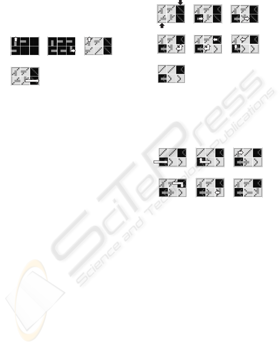
2.4 Cicatrization
Fig. 6f, shows the normal behavior of a healthy min-
imal cell, i.e. a cell without any faulty molecule. A
molecule is considered as faulty, or in the faulty mode,
if some built-in self-test detects a lethal malfunction.
Starting with the normal behavior of Fig. 6f, we sup-
pose that two molecules will become suddenly faulty
(Fig. 8a): (1) The lower left molecule, which is in the
living mode. (2) The upper right molecule, which is in
the spare mode. While there is no change for the up-
per right molecule, which is just no more able to play
the role of a spare molecule, the lower left one triggers
a cicatrization mechanism. This mechanism is made
up of a repair process involving eastward propagating
repair signals (Fig. 8b-c) followed by a reset process
performed with westward and northward propagating
internal reset signals (Fig. 8d-g). This tissue, com-
prising now two molecules in the faulty mode and
two molecules in the repair mode, is ready for be-
ing reconfigured by the functional configuration data.
This implies a functional growth process bypassing
the faulty molecules (Fig. 9).
2.5 Regeneration
Our minimal system comprises a single spare
molecule per row and tolerates therefore only one
faulty molecule in each row. A second faulty
molecule in the same row will cause the death of the
whole cell, and the start of a regeneration mechanism.
Fig. 10 illustrates the repair process and kill process
involved in this mechanism. Starting with the nor-
mal behavior of the cicatrized cell (Fig. 9f), a new
(a)
(b) (c)
(d)
(e)
(f)
(g)
Figure 8: Cicatrization mechanism performed as a repair
process followed by a reset process. (a) Living and spare
molecules becoming faulty. (b-c) Generation of repair sig-
nals propagating eastward. (d-f) Generation of internal re-
set signals propagating westward and northward. (g) Cell,
comprising two faulty and two repair molecules, ready for
functional reconfiguration.
(a)
(b)
(c)
(d)
(e)
(f)
Figure 9: Functional reconfiguration of the living and repair
molecules. (a) External growth signal bypassing the lower
left faulty molecule. (b-e) Generation of internal growth
signals to build a functional data path bypassing the faulty
molecules. (f) Closed functional data path within the living
and repair molecules.
molecule, the upper middle one, becomes faulty. In a
first step, the new faulty molecule sends a repair sig-
nal eastward, in order to look for a spare molecule,
able to replace it (Fig. 10b). In a second step, the sup-
posed spare molecule, which is in fact a faulty one,
enters the lethal dead mode and triggers kill signals
which propagate northward, westward and southward
(Fig. 10c-f). Finally in Fig. 10g, all the molecules of
the array are dead as well as our minimal system.
BIO-INSPIRED DATA AND SIGNALS CELLULAR SYSTEMS
205
(a)
(b) (c)
(d)
(e)
(f)
(g)
Figure 10: Regeneration mechanism performed as a repair
process followed by a kill process. (a) Living molecule be-
coming faulty. (b) Eastward repair signal. (c-f) Genera-
tion of internal and external kill signals propagating north-
ward, westward and southward. (g) Cell made up six dead
molecules.
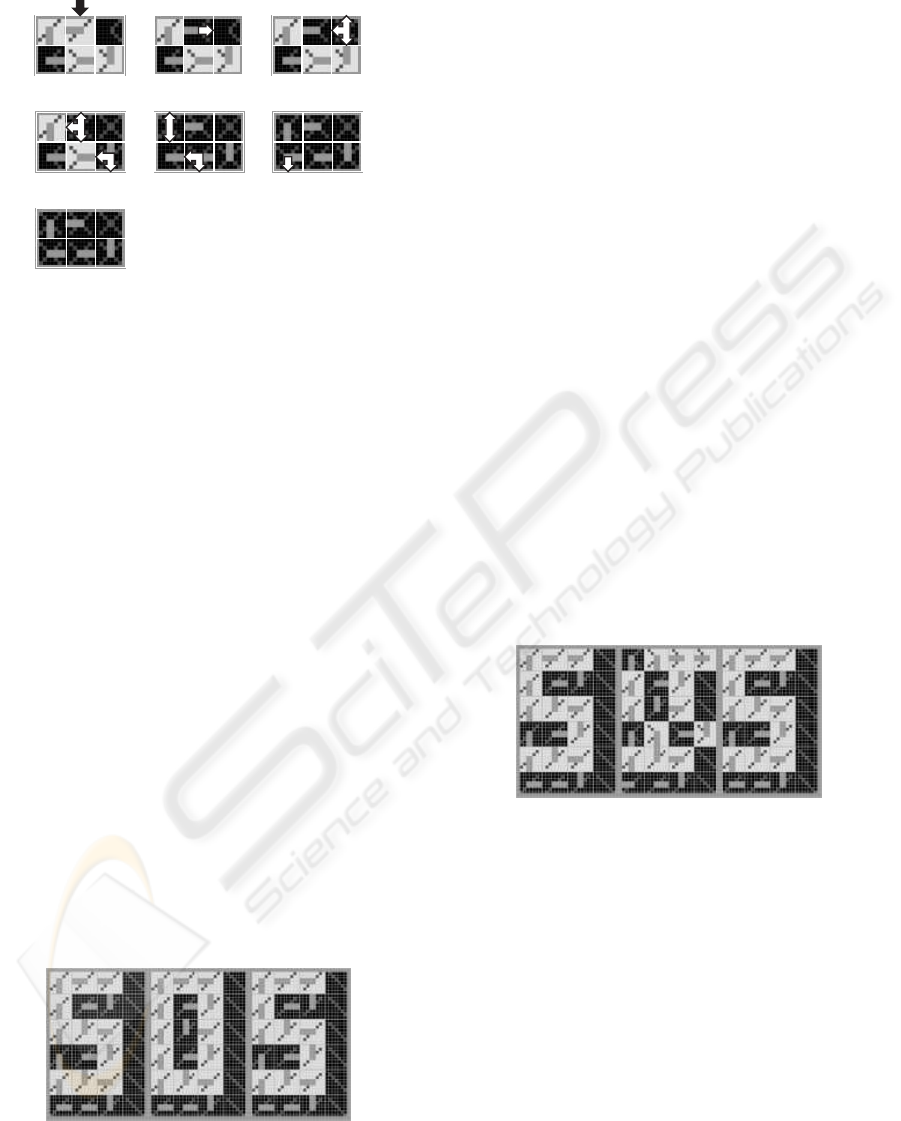
3 SOS ACRONYM APPLICATION
3.1 Structural Configuration,
Functional Configuration and
Cloning
Even if our final goal is the self-organization of com-
plex bio-inspired data and signals cellular systems,
we will use an extremely simplified application ex-
ample, the display of the “SOS” acronym, in order
to illustrate its basic mechanisms. The system that
displays the acronym can be considered as a one-
dimensional artificial organism composed of three
cells (Fig. 11). Each cell is identified by a X coor-
dinate, ranging from 1 to 3. For coordinate values
X = 1 and X = 3, the cell implements the S character,
for X = 2, it implements the O character. Such a cell,
capable of displaying either the S or the O character,
is a totipotent cell comprising 4× 6 = 24 molecules.
X=1
2 3
Figure 11: One-dimensional organism composed of three
cells resulting from the structural configuration, functional
configuration and cloning mechanisms applied to a totipo-
tent cell.
In order to build the multicellular organism of
Fig. 11, the structural configuration mechanism, the
functional configuration mechanism, and the cloning
mechanism are applied at the cellular level. Starting
with the structural and functional configuration data
of the totipotent cell, these mechanisms generate suc-
cessively the three cells X = 1 to X = 3 of the organ-
ism “SOS”.
3.2 Cicatrization and Functional
Reconfiguration
The cicatrization mechanism (or cellular self-repair)
results from the introduction in each cell of one col-
umn of spare molecules (Fig. 11), defined by the
structural configuration of the totipotent cell, and the
automatic detection of faulty molecules. Thanks to
this mechanism, each of the two faulty molecules
of the middle cell (Fig. 12) is deactivated, isolated
from the network, and replaced by the nearest right
molecule, which will itself be replaced by the near-
est right molecule, and so on until a spare molecule is
reached. The functional reconfiguration mechanism
takes then place in order to regenerate the O charac-
ter of the organism “SOS”. As shown in Fig. 12, the
regenerated character presents some graphical distor-
tion.
X=1
2 3
Figure 12: Graphical distortion resulting from the cicatriza-
tion and reconfiguration mechanisms applied to the middle
cell of the organism.
3.3 Regeneration
The totipotent cell of the organism “SOS” havingonly
one spare column allows only one faulty molecule per
row. When a second one is detected, the regeneration
mechanism (or organismicself-repair) takes place and
the entire column of all cells to which the faulty cell
belongs is considered faulty and is deactivated (col-
umn X = 2 in Fig. 13; in this simple example, the col-
umn of cells is reduced to a single cell). All the func-
tions (X coordinate and configuration) of the cells to
the right of the column X = 1 are shifted by one col-
umn to the right. Obviously, this process requires as
BIOSIGNALS 2008 - International Conference on Bio-inspired Systems and Signal Processing
206

many spare cells to the right of the array as there are
faulty cells to repair. As shown in Fig. 13, the repara-
tion of one faulty cell needs one spare cell to the right
and leaves a scar in the organism “SOS”.
X=1
2 3
Figure 13: Scar resulting from the regeneration mechanism
applied to the organism.
4 CONCLUSIONS
The self-organizing mechanisms are made of simple
processes like growth, load, branching, repair, reset,
and kill. They allow the data and signals cellular
systems to possess three bio-inspired properties: (1)
Cloning or self-replication at cellular and organismic
levels. (2) Cicatrization or self-repair at the cellular
level. (3) Regeneration or self-repair at the organis-
mic level.
Starting with a very simple system, a cell made
of six molecules, we realized digital simulations in
order to describe the data and signals involved in the
self-organizing mechanisms. The “SOS” acronym, an
organism made of three cells, was introduced as an
application example for the simulation of our mecha-
nisms and processes.
The functional configuration mechanism pre-
sented here will be implemented in the ubichip (Up-
egui et al., 2007), a programmable circuit that draws
inspiration from the multi-cellular structure of com-
plex biological organisms.
REFERENCES
Mange, D., Stauffer, A., Petraglio, E., and Tempesti, G.
(2004). Self-replicating loop with universal construc-
tion. Physica D, 191(1-2):178–192.
Stauffer, A., Mange, D., and Tempesti, G. (2005). Em-
bryonic machines that grow, self-replicate and self-
repair. In J. Lohn, e. a., editor, Proceedings of the
2005 NASA/DoD Conference on Evolvable Hardware
(EH’05), pages 290–293. IEEE Computer Society,
Los Alamitos, CA.
Stauffer, A., Mange, D., and Tempesti, G. (2006). Bio-
inspired computing machines with self-repair mecha-
nisms. In Ijspert, A., Masuzawa, T., and Kusumoto,
S., editors, Biologically Inspired Approaches to Ad-
vanced Information Technology. Proceedings of The
Second International Workshop Bio-ADIT 2006, Lec-
ture Notes in Computer Science. Springer-Verlag,
Heidelberg.
Upegui, A., Thomas, Y., Sanchez, E., Perez-Uribe, A.,
Moreno, J.-M., and Madredas, J. (2007). The Per-
plexus bio-inspired reconfigurable circuit. In J. Lohn,
e. a., editor, Proceedings of the NASA/ESA Conference
on Adaptative Hardware and Systems (AHS-2007),
pages 600–605. IEEE Computer Society, Los Alami-
tos, CA.
BIO-INSPIRED DATA AND SIGNALS CELLULAR SYSTEMS
207
