
WIDEBAND WIRELESS LINK FOR BCI CONTROL
100 kHz – 8/16 Channel for High Resolution EEG
C. P. Figueiredo, N. Dias, J. H. Correia and P. M. Mendes
DEI, University of Minho, Campus de Azurém, 4800-058 Guimarães, Portugal
Keywords: Wireless, Wideband, Biotelemetry, BCI.
Abstract: This work presents a solution to obtain a wireless biopotential acquisition system with high data rate.
Wireless systems are currently emerging with the possibility of being used for monitorization of several
physiological parameters. However, most of the solutions are based on standard wireless systems. Besides
the wireless throughput limitation, those systems are also limited in their software solutions and data
acquisition capabilities. A trade-off solution between commercial of-the-shelf and custom design was
explored by interfacing a MICAz with external instrumentation, while maximizing the rate of
communication. The wireless system is being used for BCI control, operates at 2.4 GHz (Zigbee compliant),
with a data rate of 250 Kbps for wireless link, and up to 1 Mbps for serial communication. Signals down to
about 23 µV can be detected, and 8/16 single-ended channels are provided with 100 kHz sampling rate.
1 INTRODUCTION
The use of wireless sensor networks to assist in
biomedical applications is being pursued by many
researchers and will become available as soon as the
required sensors and network solutions are made
available (Schwiebert et al. 2001). However, before
turning it into reality there are a few challenges to
overcome.
The system must have low power consumption
and the network nodes must operate under limited
computation. Also, since these systems must operate
in the human body, they do have some material
constraints. Moreover, continuous operation is
required, with high robustness and fault tolerance
capability (Schwiebert et al.). Recently, the
widespread availability of low power sensor devices
with physiological monitoring ability is pushing
researchers to include them in smart suits that can be
used to monitor biological signals in different
situations. Their application ranges from
monitorization embedded in space suits (Simons et
al. 2004), to monitorization during jogging activity
(Marculescu et al. 2003).
However, the requirements of sending only
cardiac or respiratory rhythm data are not enough
anymore for modern monitorizing systems. Today,
in many monitorization devices, it is necessary to
route all the acquired data for storage and further
processing. The development trend on physiological
data acquisition is demanding more and more
available bandwidth. As an example, the Brain-
Computer Interface (BCI) operation, demands
several electroencephalogram (EEG) channels with
large bandwidth, which leads to large information
amounts handling for feature and artefact extraction.
BCI is trusted to be a very useful tool for
impaired people, both in invasive and non-invasive
way. Although subjects using invasive approaches
usually show evidence of better device control than
non-invasive method users, it is barely preferred due
to the high risk involved in its research and practical
implementation. BCI has the potential to enable
people to control a device with their brain signals. In
several studies, different BCI approaches have been
tested that enable impaired people to communicate
and control specific devices (Wolpaw et al. 2000).
This paper will start with the presentation of the
hardware platform that was used in this work.
Afterwards, the requirements for physiological data
acquisition for BCI are introduced, as well as the
required hardware modifications. After highlighting
the limitations of the available platform, a solution is
proposed to overcome them and the obtained results
are presented.
202
P. Figueiredo C., Dias N., H. Correia J. and M. Mendes P. (2008).
WIDEBAND WIRELESS LINK FOR BCI CONTROL - 100 kHz – 8/16 Channel for High Resolution EEG.
In Proceedings of the First International Conference on Biomedical Electronics and Devices, pages 202-205
DOI: 10.5220/0001054102020205
Copyright
c
SciTePress
2 WIRELESS BCI
The BCI system is mainly made by four
software/hardware modules: (1) EEG signal
acquisition, (2) features extraction, (3) translation
algorithm, and (4) actuator and feedback system.
The system that is being used for BCI records
EEG data using a Labview platform, which receives
data from a BrainProducts® Quickamp through a
socket connection. The Data are digitized at 250 Hz
and passed through a 6th order (48 dB per octave)
band-pass Butterworth filter of 1-50Hz. This
platform extracts the subject specific features,
provides feedback and graphical interface to subject.
There are many challenges to be solved before
BCI systems can show their full potential. A
wideband low-power wireless acquisition platform is
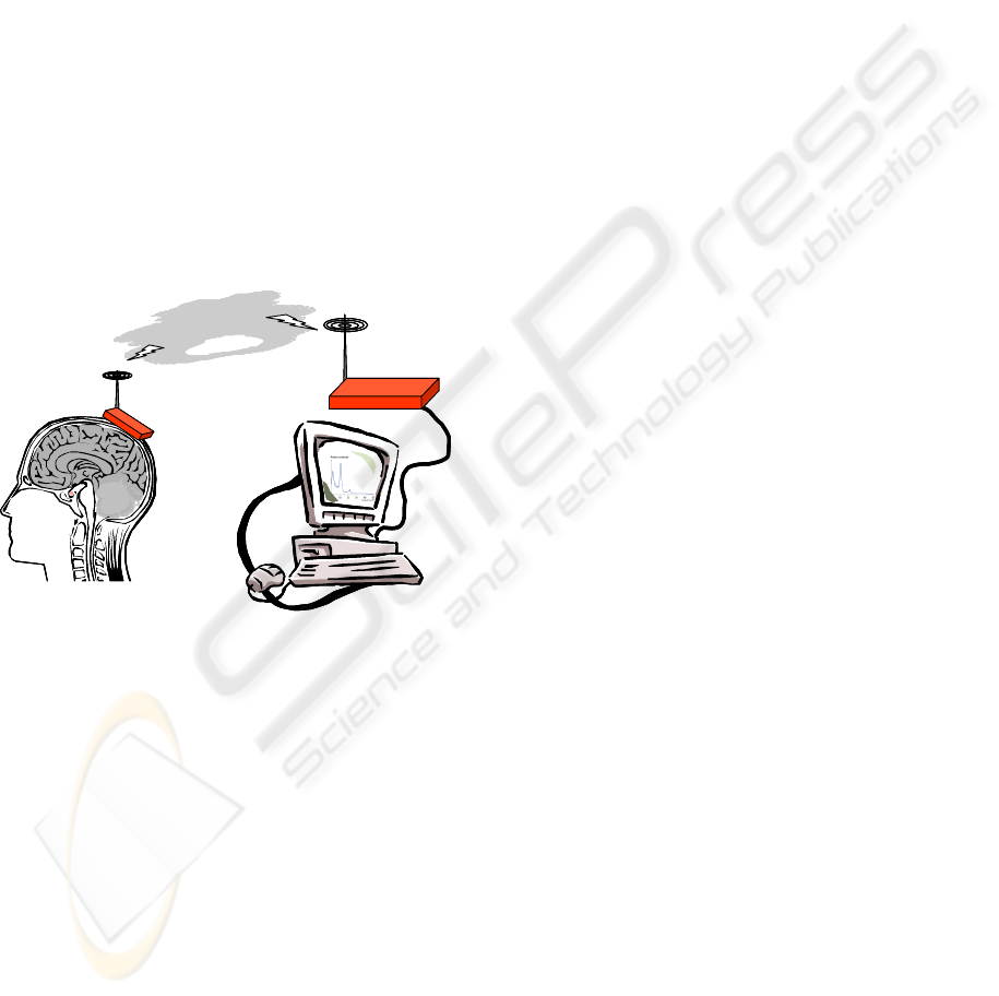
of most relevance for BCI operation. Fig. 1 shows a
possible solution for a wireless BCI system. The
presented solution uses a ZigBee link to transmit the
EEG signals.
Z
i
g
B
e
e
S
e
r
i
a
l
L
i
n
k
Z
i
g
B
e
e
S
e
r
i
a
l
L
i
n
k
Figure 1: Wireless BCI system under development, (red
modules are the target of this work).
2.1 Wideband BCI
A BCI is usually based on the ongoing rhythms of
EEG signals. Those rhythms are the so called delta
(0.5-4 Hz), theta (4-7.5 Hz), alpha (7.5-13 Hz), beta
(15-20 Hz) and gamma waves (20-42 Hz). A
bandwidth of 100 Hz would suffice for the
acquisition of these potentials. However, during BCI
operation, the reactivity of a rhythm to a mental task
is usually identified in power spectra that are
calculated using the FFT algorithm.
A good BCI control, from the user point of view,
is a system with real time feedback. Any action will
happen as soon as the user thinks about it. To obtain
this, the system should collect as much data as
possible in the shortest period of time, limited by the
spectral resolution required. In this way, for a
specific time window, the higher the number of
sampled points, the higher is the spectral content in
the calculated spectra. Once 1000 samples per
second are recorded, the FFT of a 1 s time window
achieves 1 Hz resolution in the frequency domain,
together with a spectral content up to 1000 Hz. This
sampling rate able the acquisition system to track
surface EMG (2-500 Hz bandwidth) signals in order
to detect task related muscle activity (Prutchi and
Norris, 2004), since a BCI system is supposed to
operate in the absence of muscle activity.
BCI systems can be greatly improved if more
complex and faster algorithms can be used but this
would require routing all the available data to a
powerful computing system. The acquisition
systems are, due to power saving requirements, very
limited to perform this task.
2.2 Wireless Platform
One key element required to implement a wireless
BCI system is the wireless platform. There are many
solutions to implement it but the MICAz is a very
popular one. This platform allows easy
implementation of a wireless sensor network formed
by individual wireless nodes. Fig. 2 a) shows the
node core available for system development. This
core includes the microcontroller, the ADC with 10
bits resolution, the ZigBee wireless interface, and
the serial interface.
The microcontroller is the ATMEL Atmega128,
running the TinyOS operating system. The micro
provides access to the ADC, allowing data
acquisition at 76.9K samples/s, with a resolution of
10 bits, from a maximum of 7 differential or
8 single-ended channels. The acquired data can then
be routed trough the wireless ZigBee link, which
allows a throughput of 250 kbps. The other option is
to route the data through the serial interface. It uses a
RS-232 link with the maximum data rate of
115.2 kbps.
2.3 Data Acquisition
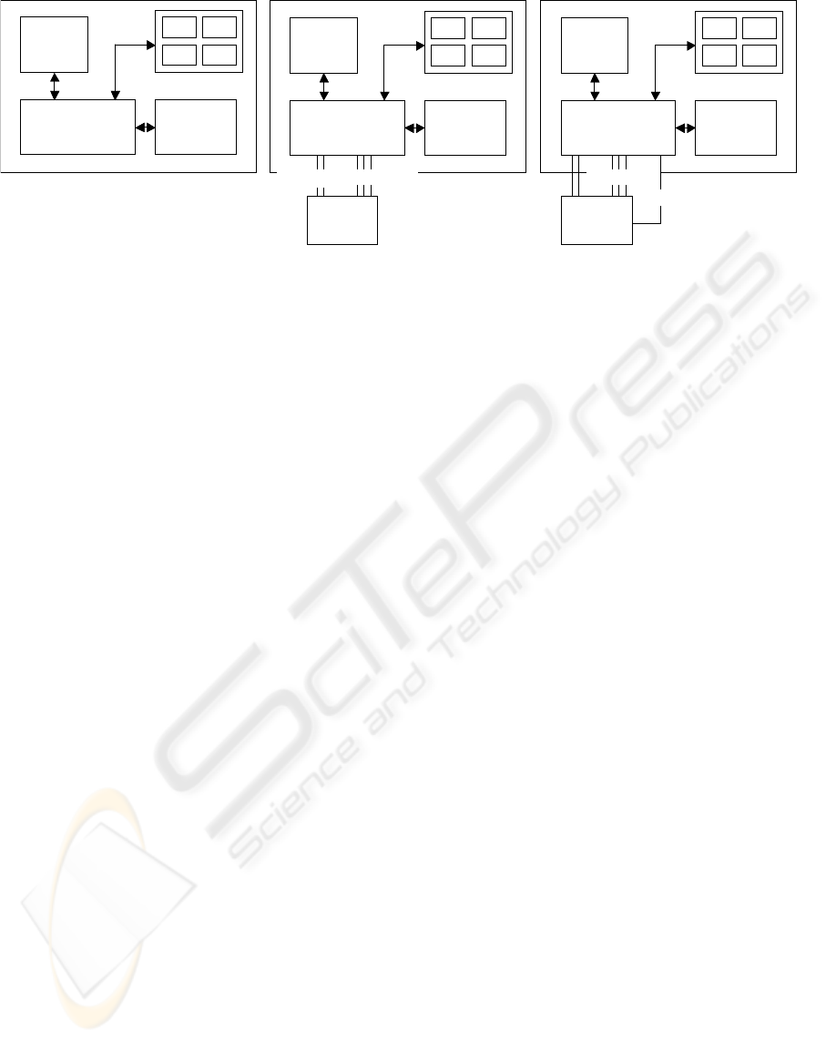
The system can use three different node types, as
shown in Fig. 2. The first is the standard wireless
platform (Fig. 2-a)), which has a microprocessor
with a built in analogue-to-digital converter (ADC).
This device allows a maximum data transfer rate of
115.2 kbps. This limitation comes from the serial
port connection (RS232), where the PC USART is
limited to this speed.
When more resolution is required, it is necessary to
use an external ADC. This is required for high
resolution EEG and ECG, e.g., to enable the
WIDEBAND WIRELESS LINK FOR BCI CONTROL - 100 kHz – 8/16 Channel for High Resolution EEG
203
Microc on tr oller
ZigBee
10-bit
ADC
Serial Interface
μC
Tri-s tate RS232
Adapter
Microc on tr oller
ZigBee
10-bit
ADC
Serial Interface
μC
Tri-s tate RS232
Adapter
Microc ontr oller
ZigBee
10-bit
ADC
Serial Interface
μC
Tri-s tate RS232
Adapter
16/24-bit
ADC
16/24-bit
ADC
Bus I
2
C/SPI
Control
Bus I
2
C/SPI
INT0
a)
b) c)
Microc on tr oller
ZigBee
10-bit
ADC
Serial Interface
μC
Tri-s tate RS232
Adapter
Microc on tr oller
ZigBee
10-bit
ADC
Serial Interface
μC
Tri-s tate RS232
Adapter
Microc ontr oller
ZigBee
10-bit
ADC
Serial Interface
μC
Tri-s tate RS232
Adapter
16/24-bit
ADC
16/24-bit
ADC
Bus I
2
C/SPI
Control
Bus I
2
C/SPI
INT0
a)
b) c)
Figure 2: Wireless nodes involved in the physiological data acquisition. a) with internal ADC; b) with external ADC driven
by software interrupt; c) with external ADC drive by hardware interrupt.
recording of EEG signals for BCI. For the second
node type it the AD7714 ADC was selected for
external operation, connected to the Mote I2C bus
using a serial link with the SPI port available in the
ADC. This solution allows 16 or 24 bits of
resolution, with a maximum sampling frequency of
1028 samples/s. However, the data acquisition from
the external ADC requires the use of commands
from the operating system, the TinyOS. Due to
operating system timings, the maximum sampling
speed is 4000 samples/s. In this way, it was
necessary to implement the third solution, which is a
modified version of solution two. Instead of
implementing all the external ADC control by
software, the time critical tasks were implemented
using hardware interruptions. With the third node
type it is possible to sample the analogue channels at
8K samples/s, with 16 or 24 bits of resolution. The
system limitation is on channel switching, made by
software, which takes 3 ADC conversion periods to
change between channels, due to resettling of the
sigma delta modulator and digital filter.
To overcome this switching limitation, the use of the
ADS8345 is proposed. It is an 8-channel, 16-bit,
sampling Analog-to-Digital (A/D) converter with a
synchronous serial interface. This ADC allows data
acquisition from 8 channels at 100 kHz. The channel
switching time is only 500 ns, and typical power
dissipation is 8mW at a 100kHz throughput rate.
2.4 Data Routing
After solving the problem of data acquisition, it is
required to send the EEG data to the host station.
This requires a wireless link and a RS-232 link. The
first hop will be the wireless link, a ZigBee link with
a data rate of 250 kbps. If we consider sampling at
1 kHz, 8 channels, and 16 bits per sample, we have
an overall data rate requirement of 128 kbps. This
means that the wireless link will be enough to
support it.
After receiving the data, the base station needs to
route it to the processing unit, a PC. This is done
using the RS-232 interface. This means we have a
bottleneck in the system since the RS-232 will allow
a maximum data transfer rate of 115.2 kbps.
However, the microcontroller Atmega128 allows the
configuration of his RS-232 port to operate at
921.6 kbps, and it is also possible to use a RS-232 to
USB interface, having the possibility to achieve a
maximum data rate of 1 Mbps. Considering this, the
bottleneck will be on the ZigBee link, but we have
then a bandwidth of 250 kbps.
3 PLATFORM PERFORMANCE
3.1 Data Acquisition
In the second solution (fig. 3 b)), the bottleneck is
the software driven interruption. To test the
maximum sampling frequency, a timer was
implemented and each sample was sent together
with its time stamp. We have found that the smallest
sampling time, Ts, is about 1s (with a 2.5 MHz
crystal). Thus, it is not a timer problem, since when
the Ts was reduced below 1ms, the system started to
fail on the delivering of some data points. In this
way, the system does not allow to obtain all the
signals at maximum sample rate. The third solution
(fig. 2-c)), with the hardware driven interruption,
was able to read 16 bit samples at a maximum data
rate of 1028 samples/s. This makes an overall bit
rate of 131584 bps, which is not a problem for the
ZigBee link. However, the data was not reaching the
host station, despite the serial configuration of
almost 1 Mbps.
BIODEVICES 2008 - International Conference on Biomedical Electronics and Devices
204
3.2 Serial Link
To test the maximum speed possible with this link, it
was used the solution of Fig. 2-c) and the INT0 line
was used to trigger the data transmission. Instead of
sending data from the ADC, the data was generated
and transmitted through the system. To detect the
wrong samples, each sample was generated from the
previous, by adding a fixed amount. In this way,
each time a sample was missed, the difference
between two consecutive samples allowed the
detection of a missing sample. The results are shown
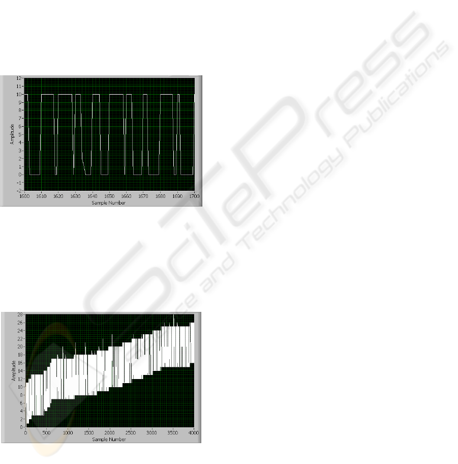
in Fig. 3 and Fig. 4. It shows the effect of increasing
the sample rate, with the nonzero values
representing instants where data packets (of 10
samples) were lost.
Figure 3: Error plot when data is sampled at 3.95 kHz.
The previous figure shows the received samples
when the interrupt signal was set to 3.95 kHz. This
corresponds to a total bit rate of 113.76 bps. From
the plot, we can see that some data values are
corrupted but the system is able to proceed with the
transmission of correct values.
Figure 4: Error plot when data is sampled at 4.3 kHz.
In the previous plot, the overall data rate is
123.84 kHz and we can see that the system is not
able anymore to recover and transmit correct values.
The microcontroller associated with this block,
which controls the programming steps of the main
microcontroller, also allows 1 Mbps and was not the
problem. The bottleneck resides on the voltage
adapter, responsible for the conversion between PC
voltage levels to the micro voltage levels.
This is the MAX3223, which guarantees only
120 kbps of throughput. Our proposal is to use the
MAX3223E, fully compatible with the available
board, which guarantees a 250 kbps throughput. If
required, another adapter for achieving higher data
rate can be used. However, the ZigBee link will limit
data rate to 250 kbps.
4 CONCLUSIONS
A solution to obtain a high date rate wireless link for
physiological data acquisition was presented,
operating at 2.4 GHz, with a minimum detectable
signal of about 23 µV, and power consumption of
15 mW. The solution is based on a MICAz mote and
is used for external ADC management as well as
transmitting the acquired data via wireless link to
another mote connected to a computer’s serial port.
The written TinyOS components detect the end of
conversion by the ADC via external interrupt,
avoiding sampling jitter, and perform read and write
operations on its registers through the SPI interface.
This solution was tested for BCI control
applications. With the proposed solution it is
possible to acquire data from 8/16 channels at 100
kHz sampling frequency, with a data rate limit of
250 kbps.
REFERENCES
Marculescu, D., et al., 2003, “E-textiles: ready to ware,”
IEEE Spectrum, Volume 40, Issue 10, pp. 28 – 32.
Prutchi, D., Norris, M., 2004, Design and Development of
Medical Electronic Instrumentation, Wiley, ISBN:
978-0-471-67623-2.
Schwiebert, L., et al., 2001, "Research Challenges in
Wireless Networks of Biomedical Sensors,"
International Conference on Mobile Computing and
Networking, Rome, Italy, pp. 151 – 165.
Simons, R. N., at al., 2004, “Spiral Chip Implantable
Radiator and Printed Loop External Receptor for RF
Telemetry in Bio-Sensor Systems,” IEEE Radio and
Wireless Conference, 19-22 Sept., pp. 203 – 206.
Wolpaw, J. R., et al., 2000, "Brain–Computer Interface
Research at the Wadsworth Center," IEEE
Transactions On Rehabilitation Engineering, vol. 8,
no. 2, pp. 222-226.
WIDEBAND WIRELESS LINK FOR BCI CONTROL - 100 kHz – 8/16 Channel for High Resolution EEG
205
