
COMPACT PULSE OXIMETER USING PIC18F4550
MICROCONTROLLER
Leonardo Zane Vilhegas, Adir José Moreira and Ronaldo Domingues Mansano
Departamento de Engenharia de Sistemas Eletrônicos
Escola Politécnica da Universidade de São Paulo
Av. Prof. Luciano Gualberto, 380 – Bloco A – Sala 46 – CEP: 05508-900, Brazil
Keywords: Oxygen Saturation, microcontroller, PIC18F4550, heart rate, USB.
Abstract: In this paper is propose one compact pulse oximeter system using a PIC18F4550 micrcontroller, which use
of USB (Universal Serial Bus) communication technology. The device has one LCD (Liquid Crystal
Display) 20x4 to continuous check and has the possibility to get one parallel communication with a PC
(Personal Computer) to analysis more detailed. The system is compound for oxygen saturation measures
(SpO
2
) and heart rate. The equipment is compact and show easy to handle and simple use.
1 INTRODUCTION
In the 80 decade beginning, already had emphasized
the necessity of the improvement and of scientific
development in the biomedic instrumentation area in
Brazil, in order to reach the excellency of the
medical services (Moraes & Vita, 1981).
With this mind and due to great integration
capacity increase of the eletronics devices, as well as
the fast technological advance of the
microcontrollers, a wide development of
applications in the diverse areas of biomedical
engineering was allowed (Moron, 2005).
The oxygen is fundamental and vital for the
correct functioning of each cell of the human body
and its absence, for a drawn out time, it can cause
the deaths of these cells (Webster, 1997). The pulse
oximetry (Moyle, 1994 - Wukitsch, 1987) is a non-
invasive method to measure the arterial oxygen
saturation (SpO
2
) using two diferents wavelenghts to
determine the relative oxyhemoglobin concentration
(HbO
2
) and deoxyhemoglobin (Hb) in the blood.
Already, the pulse oximeter is a device that uses an
empirical measurement method and actually is an
important SpO
2
continuous monitor device where it
offers oxygen saturation results trustworthy similar
the convencional methods.
In this article is propose a development of the
compact pulse oximeter system. The system is
compound for one prototype sensor, one software
interface and one pulse oximeter device with a LCD
20x4, where the device contained one PIC18F4550
microcontroller that produce all control of the
circuit. The PIC contained the USB technology
integrated where the implementation and
compacting was easily.
The primary interface has been the ubiquitous
serial port. Intel developed the USB in the early 90s,
and while many personal computers peripherals now
support this interface. Each USB port can support up
to 127 devices (Lichtel, 2004).
2 MATERIALS AND METHODS
2.1 Overview of the System
The aim of this study is to design and implement one
compact system and with handle facilities and use to
SpO
2
monitoring and heart rate. The figure 1 shows
the architecture of the considered and developed
system.
The major design requirements of project was
the following: a) It should be portable and easy
mobility; b) it should be easiness to get na supply
source; c) it should have a userfriendly interface; d)
Compacting of the circuit using the PIC18F4550; e)
Possibility to record the data received in a PC; f) it
should collect physiological data of arterial oxygen
saturation and the heart rate (BPM).
194
Zane Vilhegas L., José Moreira A. and Domingues Mansano R. (2008).
COMPACT PULSE OXIMETER USING PIC18F4550 MICROCONTROLLER.
In Proceedings of the First International Conference on Biomedical Electronics and Devices, pages 194-197
DOI: 10.5220/0001053701940197
Copyright
c
SciTePress
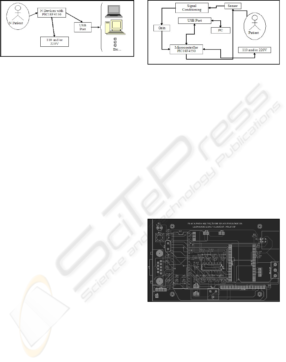
Figure 1: Overview of the development system. Device
can be supply by PC or directly by AC 110/220V, using a
converter to 5V.
2.2 Prototype Sensor
In the prototype device of the article hadn`t been use
neither comercial sensor, it was developed one
prototype sensor using comercials LEDs from
CROMATEK and one photodiode TSL251R, from
TAOSINC ,with transimpedance amplifier
integrated. The LEDs has wavelengths of 660nm
(red) and 940nm (infrared). The photodiode choice
was done by yours caracteristics and someone are
about transimpedance amplifier integrated, rise time
about 70us, linear voltage response in respect to
intensity light, spectral response and good angular
displacement, becoming the alignment between
emitter and receptor less critical.
2.3 Physiological Acquisition Signals
Device
The compact pulse oximeter device using the
microcontroller PIC18F4550 has the circuit supply
directly by USB port. Using the USB cable, the
device can be conect directly in PC and/or using the
adaptor, where can be connected directly to
electricity network and visualize the data directly on
the LCD.
The USB port has 5V and 500mA, this is enough
to supply the circuit. The circuit is compound for
first condicionning step signal, that proceeding from
the sensor, that have a filter pass-band and a signal
gain. After the signal treatment the PIC is
responsible for diverse other necessary functions of
the pulse oximeter device. The sampling frequency
that the microcontroller works is 1kHz and takes
care of to the necessities of the Nyquist theorem and
prevents the aliasing problem. The prototype also
has a LCD 20x4 to visualize the data received for
the optic sensor. The implementation of the LCD in
the system becomes interesting therefore is not
necessary no complex computational system to get
the value of SpO2 and the cardiac beating. In figure
2 the diagram of blocks of the physiological signals
acquisition system can more be seen detailed.
Figure 2: Diagram of blocks of the compact pulse
oximeter device.
3 RESULTS
All the prototype system had been developed and
implemented. The device (already with protection
circuit), which includes the physiological signals is
compound (120x80x30mm) and light (<300g). In
figure 3 the image prototype device circuit can be
seen. The photo of the pulse oximeter with LCD
connected together with the USB cable and the
eletricity network found in the figure 4. For the
sensor development was done one
photospectroscopy of the LEDs that had been used
in the prototype, to verify if they are in the specific
band wavelenght fo the aplication. In figure 5, the
graphs of the tests realized through with the emitters
can be seen.
Figure 3: Image of the prototype pulse oximeter device
circuit using the PIC18F4550.
The prototype sensor was development with the
concern to keep total isolated of the invironment. In
figure 6 it can be seen the sensor images, the
armored cable and used connector DB9 to realize the
connection with device.
COMPACT PULSE OXIMETER USING PIC18F4550 MICROCONTROLLER
195
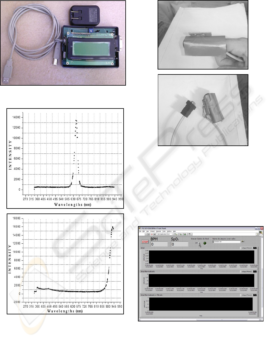
Figure 4: Photograph of the device with the connected
LCD, USB cable and adapter for electricity network.
a)
b)
Figure 5: Photospectroscopy: a) LED 660nm (red); b)
LED 940nm (infrared).
The program of use for interface the pulse
oximeter device with the PC was developed through
the utilization of LabVIEW software. The program
has the information about amount of oxygen arterial
blood
(SpO
2
), of the photopletysmography signal
a)
b)
Figure 6: Pototype sensor: a) Sensor to hardwired to the
indicating finger; b) Sensor with covering against
surrounding light connected with one armored cable and
connector DB9.
and heart rate. The software also diverse other
funtions as for example, to record the data of the
signals received by device, acknowledgment of
emergency, etc. In figure 7 the display of the
software main control developed for interface of the
system can been seen.
Figure 7: Main display of the responsible interface fo the
communication with the device.
BIODEVICES 2008 - International Conference on Biomedical Electronics and Devices
196

4 CONCLUSIONS
The pulse oximeter device using the microcontroller
PIC18F4550 was developed. In the module are
measured physiological samples of oxygen
saturation in the arterial pulse, of
photopletysmography and heart rate. The software
developed to interface with the computer revealed
very friendly however. With resources limited fo not
being the focus of the article. The data presented in
the LCD are oxygen saturation and cardiac
frequency. The supply device for the USB port using
a PC or the adapter presented great easiness and
fastest in its aplication. The photopletysmography
are not presented in the LCD for the display not to
be graphical.
REFERENCES
Costill, D. L., Wilmore, J. H., Fisiologia do Esporte e do
Exercício, São Paulo, Segunda edição, Ed. Manole,
2001.
Lichtel, D.: Implementing a USB Equipment Interface
Using the Microchip PIC16C745, QEX, June, 2004.
Moraes, J.C.T.B.; VITA, G.M.; Desafios de problemas da
saúde no Brasil à Engenharia Biomédica, Rio de
Janeiro, Anais do VII Congresso Brasileiro de
Engenharia Biomédica, p.137-7, 1981.
Moron, M.J.; Casilari, E.; Luque, R.; Gazquez, J.A.; A
wireless monitoring system for pulse-oximetry sensors,
Systems Communications, 79 – 84, 2005.
Webster, J.G.; Design of pulse oximeters. 1.ed. U.K.,
Bristol, 1997.
Moyle J., Pulse Oximitery. 1994: BMJ Publishing Group.
Wukitsch M., Pulse oximitery: Historical review of
Ohmeda functional analysis, Journal of Clinical
Monitoring and Computing, 4, 161–166, 1987.
COMPACT PULSE OXIMETER USING PIC18F4550 MICROCONTROLLER
197
