
FPGA-BASED COMPUTATION OF THE INDUCTANCE OF
COILS USED FOR THE MAGNETIC STIMULATION OF THE
NERVOUS SYSTEM
Ionuţ Trestian, Octavian Creţ, Laura Creţ, Lucia Văcariu, Radu Tudoran
Computer Science and Electrotechnics Department, Technical University of Cluj-Napoca, Cluj-Napoca, Romania
Florent de Dinechin
LIP, Ecole Normale Supérieure de Lyon, UMR CNRS / INRIA / ENS-Lyon / Université Claude Bernard Lyon 1
Keywords: Magnetic stimulation, slinky coils, inductance computation, FPGA, floating point, VHDL
Abstract: In the last years the interest for magnetic stimulation of the human nervous tissue has increased
considerably, because this technique has proved its utility and applicability both as a diagnostic and as a
treatment instrument. Research in this domain is aimed at removing some of the disadvantages of the
technique: the lack of focalization of the stimulated region and the reduced efficiency of the energetic
transfer from the stimulating coil to the tissue. Better stimulation coils can solve these problems. Designing
coils is so far a trial-and error process, relying on very compute-intensive simulations. In software, such a
simulation has a very high running time. This paper proposes and demonstrates an FPGA-based hardware
implementation of this simulation, which reduces the computation time by 4 orders of magnitude. Thanks to
this powerful tool, some significant improvements in the design of the coils have already been obtained.
1 INTRODUCTION
The preoccupation for improving the quality of life,
for persons with different handicaps, led to extended
research in the area of functional stimulation. Due to
its advantages compared to electrical stimulation,
magnetic stimulation of the human nervous system
is now a common technique in modern medicine
(Mozek and Flak, 1999).
A difficulty of this technique is the need for
accurate focal stimulation. Another one is the low
efficiency of power transfer from the coil to the
tissue. To address these difficulties, coils with
special geometries must be designed.
This process requires testing a huge number of
geometries to find an adequate solution for the
desired application (Griškoval and Höppner, 2006).
One of the major problems that appear in the
design phase is the computation of the inductivity of
the stimulating coil. For simple shapes of the coils
(circular), one can determine analytical computation
formulas. When, however, the shape and the spatial
distribution of the coil’s turns do not belong to one
of the known structures, a numerical method needs
to be used for determining the inductivity.
The idea is to divide the coils in small portions.
Starting from this method, two computation systems
are presented in the paper:
• The first one is classical and it just consists of a
software implementation (Matlab);
• The second one consists of realizing a hardware
architecture that exploits the intrinsic parallelism
of the problem. The physical support of this
architecture is an FPGA device.
The problem with the software implementation is
its running time. Coils are designed by trial-and-
error, and this approach is impractical if each trial
requires half a day of computation. Besides, as this
time grows with the complexity of the coil, it
prevents designing complex coils. This paper shows
that FPGA-based hardware acceleration is able to
solve this bottleneck.
The simulation of magnetic stimulators with
complex forms requires dividing their coils in
several parts. The self-inductance of the circuit,
divided in n parts, can be computed with formula
151
Trestian I., Cre¸t O., Cre¸t L., V
ˇ
acariu L., Tudoran R. and de Dinechin F. (2008).
FPGA-BASED COMPUTATION OF THE INDUCTANCE OF COILS USED FOR THE MAGNETIC STIMULATION OF THE NERVOUS SYSTEM.
In Proceedings of the First International Conference on Biomedical Electronics and Devices, pages 151-155
DOI: 10.5220/0001050301510155
Copyright
c
SciTePress
(1). This mainly adds up the self-inductivities of the
separate segments with the mutual inductivities of
all the involved segments. The method is well
described in (Creţ et. al., 2007); the operations
involved in computing the inductivity of a coil are:
logarithm, division, addition and multiplication.
()
kiforMLL
n
k
n
i
ki
n
k
k
≠+=
∑∑∑
===
,
111
(1)
2 SOFTWARE
IMPLEMENTATION
A coil is made up of a certain number of turns rolled
around a central rod. Each turn can be considered as
a perfect circle. The coil is structured on several
vertical stages. On each stage there are more turns
(horizontal turns). The coils parameters are: the
radius, the diameter of the metallic turn and the
distance (insulation) between consecutive turns.
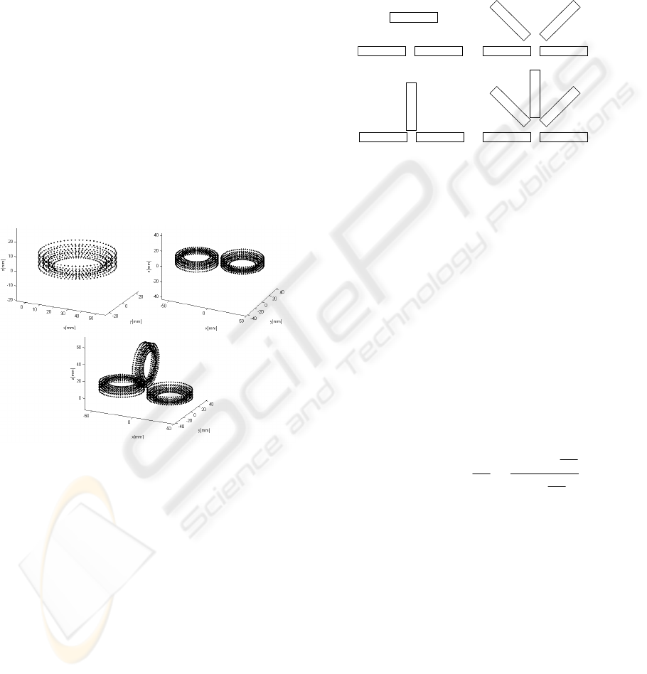
Figure 1: Coil approximation using a finite number of
points.
It is possible to have a different number of turns
on every vertical stage. It is also possible to have a
variable number of vertical stages, as shown in
Figure 1. A complete magnetic stimulation device
contains a Slinky coil. Considering a coil with N
turns, the “Slinky-k” coil is generated by spatially
locating these turns at successive angles of
()
1/180x −ki degrees, were i = 0, 1, …, k-1. If the
current passing through this coil is I, then the central
leg carries the total current N x I. These coils are
shown in Figure 2, where each rectangle represents a
leaf of the coil, viewed in perspective.
The turns are approximated by a finite number of
points. We considered, after a series of tests, that a
suitable amount of points on a turn is 64.
We have to take each of the 64 points and
combine them into segments made up of one point
and the consecutive one. After this, each segment is
held as a reference. Then, formula (1) is applied
using this reference segment and all the other
segments on the coil. For each pair of segments a
value is obtained. These values must be added in
order to obtain the coil’s total inductance.
Slinky_1
Slinky_2
Slinky_3
Slinky_4
Slinky_5
Figure 2: Magnetic coil structures of the stimulation
device.
There are two phases in the functioning of the
software implementation:
• In Phase 1, the coordinates of the points are
generated. These are computed using
trigonometric functions. The results
produced in this phase are also used in the
hardware implementation.
• In Phase 2, the actual computation of the
values is performed. Finally, we
accumulate the values corresponding to the
mutual and self inductivities.
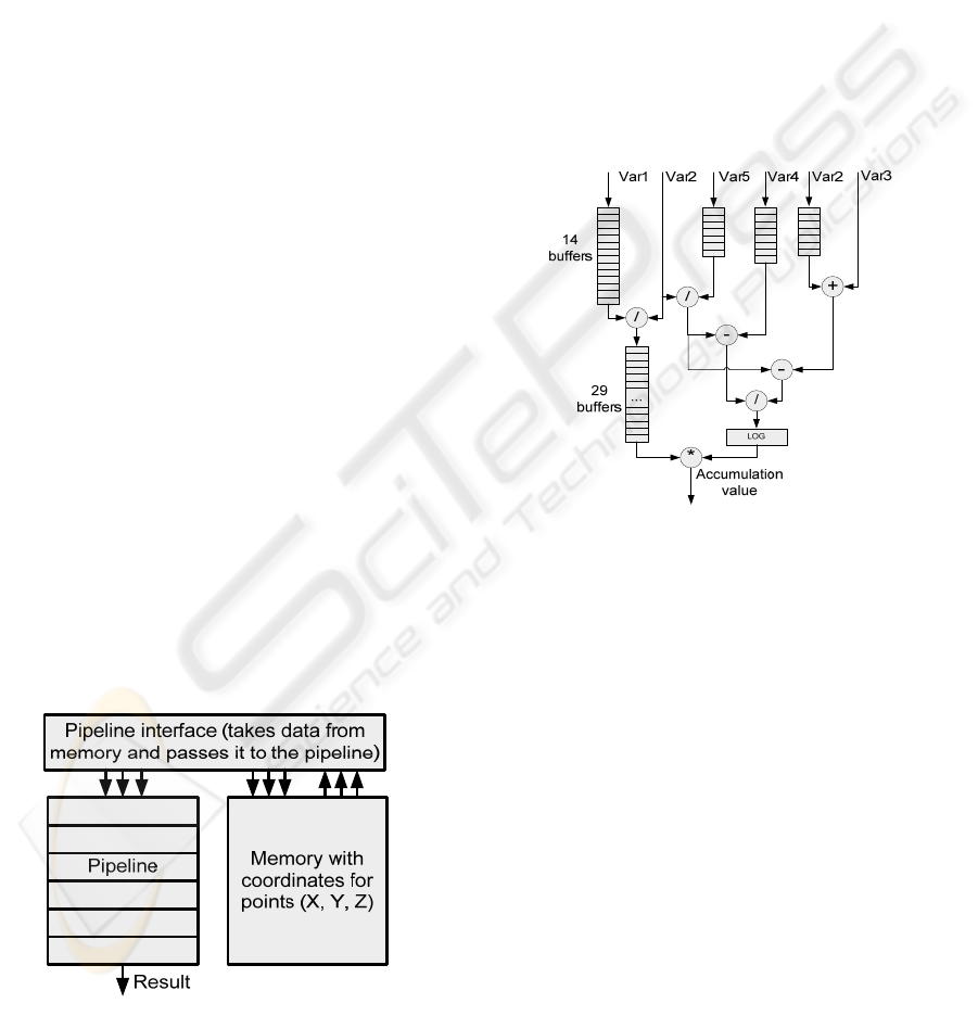
The accumulation value includes some
intermediate values (var1 to 5) according to (Creţ et.
al., 2007):
2
5
4
2
5
23
2
1
var
var
var
var
var
varvar
log
var
var
rAccumulato rAccumulato
−
−+
⋅+=
(2)
The software implementation’s main drawback
is the extremely high running time, which can be in
the order of tens of minutes even for simple
configurations. For complex geometries of the coils,
it can exceed several hours (for instance, for a 58-
turns coil, about 5 hours run time on a recent PC).
3 HARDWARE
IMPLEMENTATION
3.1 FPLibrary
A Field-Programmable Gate Array (FPGA) is a
semiconductor device containing programmable
BIODEVICES 2008 - International Conference on Biomedical Electronics and Devices
152
logic components (“logic blocks”), and interconnect.
Logic blocks can be programmed to perform simple
or more complex functions. In most FPGAs, the
logic blocks also include memory elements, from
flip-flops to more complete blocks of memories.
The hierarchy of programmable interconnects
allows logic blocks to be interconnected as needed
by the system designer, somewhat like a one-chip
programmable breadboard. Logic blocks and
interconnects can be programmed by the
customer/designer, after the FPGA is manufactured,
to implement any logical function (Guell et. al.,
2007).
Several libraries of floating-point operators for
FPGAs have been published. In this work, we use
FPLibrary, developed at Ecole Normale Supérieure
de Lyon (Detrey and De Dinechin, 2005) and freely
downloadable (Detrey and De Dinechin, 2007).
Mantissa size and exponent size parameterize each
operator in FPLibrary, allowing one to choose the
precision and the dynamic range of the numbers. It
provides operators for addition, subtraction,
multiplication, division and square root, some useful
conversions and some elementary functions
(currently exponential, logarithm and sine/cosine). It
is written in portable VHDL (Collange et al., 2006).
3.2 System Architecture
The hardware implementation implies the same two
phases as the software one, but Phase 1 is not
computation-intensive and its implementation is kept
in software.
In the Figure 3 below a block diagram of the
system is displayed. Three main blocks can be
distinguished. The most important block is the
pipeline stage, which receives values, computes
them, and in a final stage accumulates them.
Figure 3: Architecture of the hardware system.
The coordinates are stored in a Block RAM
memory. There are 3 memories, one for each
coordinate, X, Y, and Z. The synchronization logic,
which gives the data to the pipeline, is implemented
in a special interface. This interface consists of
counters and latches. The counters are orchestrated
to generate the proper addresses, while the latches
are needed to implement a caching logic, which
saves some of the memory used.
The design of the Accumulator is the most
important part of the pipeline’s architecture, since it
computes intermediary values and at the end
provides the final result. As mentioned above,
special considerations need to be made with regard
to the accumulator because of the latencies
introduced by the adders in the FPlibrary (3 cycles).
Figure 4: Second stage. Computing accumulation value.
The values that will be accumulated come and
enter the final stage, which is an accumulator having
a classical structure, using a feedback input.
3.3 Hardware Implementation Issues
The performance and feasibility of the hardware
implementation largely depends on its physical
support. Our hardware platform was a Digilent Inc.
board populated with a Xilinx Virtex2PRO30 FPGA
device. The problem with this implementation was
that it is quite large: it depleted the space of the
FPGA device we had available at this moment. To
estimate the total space needed, we synthesized the
design for a larger FPGA device (a Virtex4 160LX).
A report of the device utilization is shown below:
Selected Device: 4vlx160ff1148-12
Number of Slices: 23656 out of 67584 35%
Number of Slice Flip Flops: 20834 out of 135168 15%
Number of 4 input LUTs: 44515 out of 135168 32%
Maximum frequency: 137.552 MHz.
FPGA-BASED COMPUTATION OF THE INDUCTANCE OF COILS USED FOR THE MAGNETIC STIMULATION
OF THE NERVOUS SYSTEM
153

The implementation fits without problems on
this Virtex4 board. Regarding an implementation on
our Virtex2Pro board two options were available.
The first option was to reduce the precision at
which the pipeline operated. This ensured a
reduction of both the buffer stages that provided the
synchronization between the stages and a reduction
in size of the operators.
This option was first implemented. We reduced
the mantissa of the operands by 10 bits. Instead of a
large mantissa having 23 bits, the mantissa now had
only 13 bits. Although the design fitted on a Virtex-
II Pro board at about 98% of its capacity, the results
obtained with this method were discouraging. They
were more then 30% off from the actual result
provided by Matlab. Therefore another method
needed to be found.
The next option was to reduce the frequency at
which the pipeline stage operates and time-multiplex
some of the resources (square root – three
occurrences in design, some of the adders). This has
the advantage of preserving the pipeline’s precision,
the cost being a reduction in speed: the operating
frequency was 85.714, MHz related to the weaker
characteristics of the FPGA device and the more
precise timing requirements.
4 EXPERIMENTAL RESULTS
The main achievement of the hardware
implementation over the software one is the
reduction in computation time. By performing one
accumulation per clock cycle the hardware solution
is indeed efficient and can be used even for the most
complex magnetic stimulation systems.
In terms of complexity, both implementations, in
software and in hardware, have the same
complexity, O(n
2
) with n being the number of
distinct segments. As mentioned in Section 4, the
specific hardware structure performs one
accumulation per clock cycle. That means that each
clock cycle, a mutual inductivity between two
segments is evaluated. The software implementation
performs the same computations in a longer time.
We have analyzed our software and hardware
implementations using the Slinky_1, Slinky_2 and
Slinky_3 configurations (Figure 2). The values are
given in Table 1, where a comparison is shown
between the results provided by the software and the
hardware solutions.
First we analyze simpler cases, 1 to 4 turns. The
outer turns are the widest turns on the coil, while the
inner ones are the neighbors of the outer turns
located closer to the center. Then, the results for
these configurations are presented. The analyzed
quantity was the inductivity. The number of
segments represents an indicator of the complexity.
The results of the two methods analyzed for the
three configurations mentioned always stayed in the
range of 3-4% of each other, with the Matlab results
being slightly bigger than the results given by the
hardware implementation. This can be attributed to
the fact that Matlab uses by default double precision
while in our system we have used only single
precision operations. Indeed, a rough worst-case
error analysis tells us that the accumulation, in the
largest coil test, of 10.1920² floating-point numbers
introduces a cumulative rounding error that may
invalidate up to log
2
(10.1920²) = 25 bits of the
result, when the mantissa of a single-precision
number holds 24 bits only.
This is a worst-case situation: in an actual
simulation, the rounding errors compensate each
other – this is why our results are still accurate.
However, it shows that we will require increasing
the precision of the floating-point format to use this
architecture on larger coils. Fortunately, this extra
precision is mostly useful in the final accumulator.
Table 1: Comparison of results.
Configuration Inductivity
(Hardware)
[μH]
Inductivity
(Software)
[μH]
Number
of
segments
1 outer turn 0.097 0.097 64
2 outer turns 0.30 0.30 128
4 turns (2 out. 2
in.)
0.92 0.93 256
Slinky_1 coil 3.81 3.9 640
Slinky_2 coil 8.4 8.6 1,280
Slinky_3 coil 13.32 13.6 1,920
The flexibility of FPGAs allows us to use
different precisions in different parts of the
architecture. Besides, a format intermediate between
single and double precision may be used. For us, a
32- or 36-bit mantissa would already be overkill
(double-precision has a 53-bits mantissa). We will
test this as soon as we get hold of a board with a
larger FPGA than the Virtex-II used here. It should
be noted that this more accurate pipeline will require
more hardware, but the same execution time: it will
still compute one accumulation per cycle.
One can see from Table 2 that the software
running time is very large, so software computation
becomes prohibitive for large systems.
BIODEVICES 2008 - International Conference on Biomedical Electronics and Devices
154
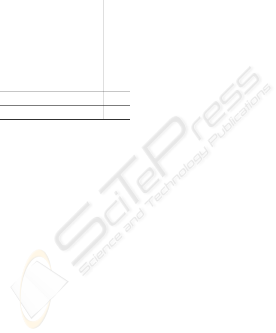
Table 2: Comparison of performance.
Configuration Duration
(hardware)
[no. of
clock
cycles]
Running
speed*
(hardware)
[seconds]
Running
speed
(software)
[seconds]
1 outer turn 40,960 0.0004
7
4.2
2 outer turns 163,84
0
0.0019
4
18
4 turns
(2 out. 2 in.)
655,36
0
0.0076
4
72
Slinky_1 coil 4,096,
000
0.0470
5
420
Slinky_2 coil 16,384
,000
0.1941
1
1,680
Slinky_3 coil 36,864
,000
0.4294
1
3,600
* at 85.714 MHz, clock period 11.66 ns
As a global comparison, the hardware solution
runs approximately four orders of magnitude faster
then the software one. The frequency is related to
the physical board we had available, but for a more
recent FPGA chip (i.e. Virtex4LX160, for which we
did some simulations, or Virtex5), the device’s
capacity as well as the working frequency will
increase, thus leading to an improved performance.
5 CONCLUSIONS AND FUTURE
WORK
An adequate geometry of the stimulation coil can
lead to a better focality of the stimulus (the ability of
a coil to stimulate a small area of the tissue) and it
can also improve the efficiency of the energy
transfer from the coil to the target tissue. The form
and size of the turns, their position inside the coil,
the insulation gap between turns are all important
parameters that should be considered when
designing a magnetic coil. Therefore, in order to
establish the most suitable coil geometry for a
specific medical application, a large number of
structures have to be tested, making of coil design a
trial-and-error process, even if the risk involved is
only computation time.
In (Creţ et. al., 2007), we analyzed the influence
that space distribution of the magnetic coils’ turns
has on the efficiency of energy transfer from the
stimulator to the target tissue. The analysis was
performed for a Slinky_3 coil configuration, with
applications on transcranial magnetic stimulation
(TMS). It turned out that the electrical energy
dissipated in the circuit of the stimulator – required
in order to achieve the activation threshold – is 25%
lower for the most efficient configuration than for
the less efficient one, and the coil heating per pulse
is also 35% smaller!
This estimation was based on the inductivity
calculus described in this paper, and the large
number of analyzed structures required a less time-
consuming computation technique, the hardware
implementation described above.
Since every medical application requires its own
optimal structure of the magnetic coil, the results
emphasized in this paper can play an important role
for future work on coil design.
Because of the large amount of operations
involved (several tens of millions just for one coil) it
is very hard to debug such a hardware system at
least at an acceptable level, but the obtained results
show an excellent concordance with those obtained
in software. Our implementation has the advantage
of greatly speeding up the computation time and
hence shortening the design process. On larger
FPGA devices the process can achieve a greater
speed by accommodating more computational
structures in parallel. These structures would
evaluate multiple pairs of segments in parallel and
accumulate them to the final value.
REFERENCES
Collange, S., Detrey, J., & De Dinechin, F. (2006).
Floating Point or LNS: Choosing the Right Arithmetic
on an Application Basis. In Proceedings of the 9
th
EUROMICRO Conference on Digital System Design,
Dubrovnik, Croatia, 197-203.
Creţ, L., Pleşa, M, Micu, D.D., & Ciupa, R. (2007).
Magnetic Coils Design for Focal Stimulation of the
Nervous System. In Proceedings of EUROCON 2007,
IEEE International Conference on Computer as a
Tool, Warsaw, Poland, 1998-2003.
Detrey, J, & De Dinechin, F. (2005). A Parameterizable
Floating-Point Logarithm Operator for FPGAs. In
Proceedings of the 39
th
Asilomar Conference on
Signals, Systems & Computers, 1186 – 1190.
Detrey, J, & De Dinechin, F. (2007). FPLibrary.
https://lipforge.ens-lyon.fr/projects/fplibrary/.
Griškova1, I., & Höppner, J. (2006). Transcranial
magnetic stimulation: the method and application.
Medicina (Kaunas), 42(10), 792-804.
Guell, D., El-Ghazawi, T., Gaj, K., & Kindratenko, V.
(2007). High-Performance Reconfigurable Computing,
IEEE Computer, 40 (3), 23-27.
Mozeg, D., & Flak, E. (1999). An Introduction to
Transcranial Magnetic Stimulation and Its Use in the
Investigation and Treatment of Depression. University
of Toronto Medical Journal, 76 (3), 158-162.
FPGA-BASED COMPUTATION OF THE INDUCTANCE OF COILS USED FOR THE MAGNETIC STIMULATION
OF THE NERVOUS SYSTEM
155
