
A MECHATRONIC DEVICE FOR THE REHABILITATION OF
ANKLE MOTION
Giuseppe Bucca, Alberto Bezzolato, Stefano Bruni
Department of Mechanical Engineering, Politecnico di Milano, Via La Masa 34, Milano, Italy
Franco Molteni
Valduce Villa Beretta Rehabilitation Centre, Italy
Keywords: Mechatronics, gait analysis, biomechanic models.
Abstract: The paper presents the main results from a research aiming at the design of an electro-mechanical actuator
to assist walking movements of the ankle articulation, for use in the rehabilitation of lower limb motion in
patients suffering neurological disease. Motivations for the research project are discussed within the
framework of the application of mechatronic concepts within rehabilitation practice. The entire design
process is then described, from the definition of project target through the mechanical concept and control
design steps until design validation by means of numerical simulations and tests on a prototype.
1 INTRODUCTION
In recent years, mechatronics has emerged as a
powerful approach to provide innovative solutions in
many technical fields related with mechanical and
electronic engineering, and also in the field of
bioengineering. This paper presents an application of
mechatronic concepts to improve the effectiveness
of therapies addressing the rehabilitation of lower
limb motion in patients suffering neurological
disease.
The project is being developed as a joint
cooperation of the Politecnico di Milano (Technical
University of Milan) and the Villa Beretta rehabilita-
tion centre, part of Valduce Hospital, and is part of
HINT@Lecco, a large research program aiming at
the promotion of research fostering new applications
in the fields of medical diagnostics and therapy.
Aim of the project is to design an electro-
mechanical actuator to assist walking movements of
the ankle articulation, referred to as “ankle actuator”.
The system has been designed for use either as
integrated with the Lokomat rehabilitation device
(Colombo et Al, 2000) presently in use at Villa
Beretta, or as a standalone device to assist
physiotherapy.
In the paper, the need and possible applications of
the ankle actuator are described under the point of
view of rehabilitation practice (Section 2), then the
results of measurements and numerical simulations
based on biomechanic multi-body models are
reported, with the aim of setting the targets for the
project (Section 3). The mechatronic design of the
system and the identification of appropriate control
strategies to meet the targets of the project are
described in Sections 4 and 5. Finally, Section 6
reports about the final assessment of system
performances, that was pursued by a combination of
testing on a prototype demonstrator and multi-
physics simulation of the actuator fitted on a person,
involving the modelling of the lower limb and of the
actuator together with the control unit.
2 USE OF THE DEVICE FOR
REHABILITATION PURPOSES
The equinovarus foot is the most common
pathological lower limb posture after lesions that
result in an upper motor neuron syndrome (UMNS).
The lack of normal motor control and/or the
presence of static foot deformity alters the cyclical
kinematic pattern of lower limb and trunk during
gait. There may be impairment of advancement of
the body weight over the supporting limb and to
56
Bucca G., Bezzolato A., Bruni S. and Molteni F. (2008).
A MECHATRONIC DEVICE FOR THE REHABILITATION OF ANKLE MOTION.
In Proceedings of the First International Conference on Biomedical Electronics and Devices, pages 56-63
DOI: 10.5220/0001047500560063
Copyright
c
SciTePress
swing the unloaded limb forward in preparation for
the next step. Foot pain, skin breakdown (lateral
border, fifth metatarsal) and knee hyperextension
(and/or varus) are frequently associated to this gait
deviation and the compensation needed for the lack
of adequate base of support, limitation of ankle
dorsiflexion, dysrhytmic and restrained forward
translation of body mass, asymmetrical weight
transfer and interference with weight bearing on the
involved limb. Gait deviations and compensations in
the involved limb induce compensations for the non-
involved limb, pain and fatigue.
The equinovarus foot impairment is the result of
different combinations of the following
dysfunctions:
a) decrease of dorsiflexor muscles motor control
during swing phase;
b) increase activity of plantarflexor muscles;
c) reduction of the elastic properties of the calf
muscles.
The main goal of rehabilitation procedures is to
maintain ankle passive range of motion , to reduce
“learning non use” due to weakness of dorsiflexor
muscles, to maintain the elastic properties of
dorsiflexor/plantarflexor muscles.
3 TARGETS FOR THE PROJECT
A first step of the research consisted in defining
quantitative targets for the mechatronic ankle
actuator, in view of allowing the correct choice of
the actuation system and the proper mechanical
design of the system. This was done through a
combination of experiments to measure relevant
gait parameters and of gait mechanics modelling
and simulation by a biomechanical multi-body
model.
3.1 Measure of Gait Parameters
An experimental campaign was performed on
healthy subjects, with the aim of obtaining the
references corresponding to correct motion, to be
reproduced under the assistance of the mechatronic
ankle actuator. Lower limb movements were
measured by means of an ELITE opto-electronic
system for motion analysis, whereas contact forces
under the footprint were measured by means of
dynamometric platforms.
These measurements allowed to quantify the
required maximum speed, maximum force and
power targets for the ankle actuator. Furthermore, a
rather large set of measured data was made
available, allowing the validation of the bio-
mechanical multi-body model in view of its use in a
later stage of the project (see Section 6.1). Some of
the experimental results are shown in the next
paragraph, where they are compared with the results
of a simulation model. Despite it is known that in
case of patients with neurological diseases, muscle
configurations may present a different situation
compared to the healthy population, the aim of this
device is to reproduce a healthy subject gait on
patients with moderate neurological diseases.
Applications on subjects with more serious diseases
have to be verified by means experimental tests.
3.2 Numerical Simulations
A multi-body human model was defined in
ADAMS/LifeMOD environment, with the aim of
complementing measurements to define the targets
of the project. Moreover, the same model was used
in a later stage of the project, being interfaced with a
model of the ankle actuator, for performance
assessment purposes (see Section 6.1).
The model includes the pelvis and the two legs,
and was used to perform inverse and forward
dynamic simulations. In the target definition phase,
numerical simulations were used to evaluate gait
parameters that could not be directly measured, as
the ankle torque, and to derive gait parameters under
conditions that could not be tested.
The multi-body model was validated based on
comparison with the measurements described in
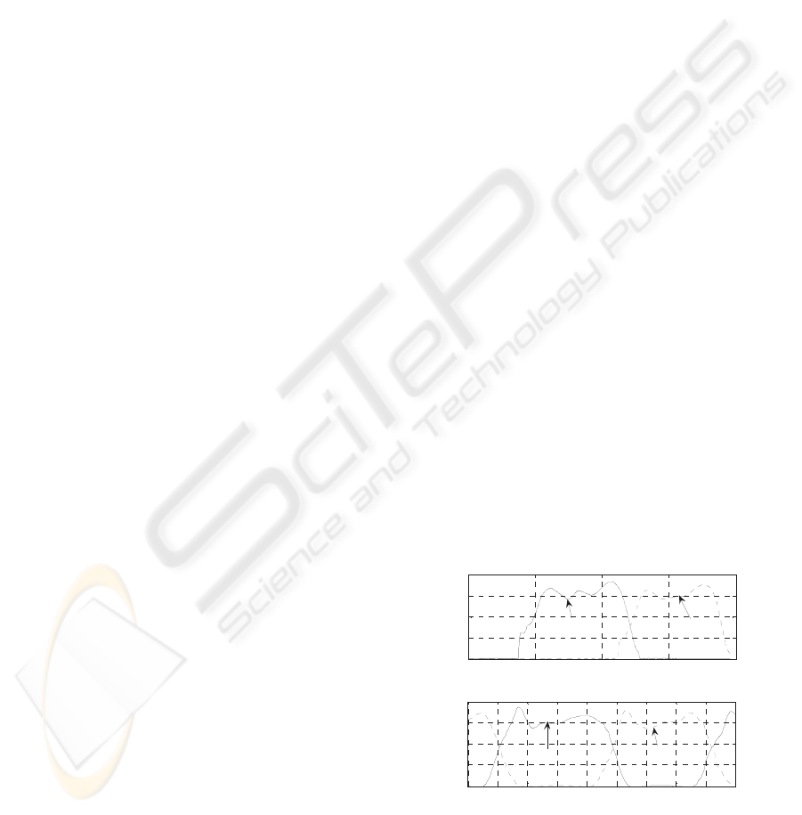
Section 3.1. As an example, Figure 1 shows the time
history of the measured and simulated vertical
contact force component for a healthy male person
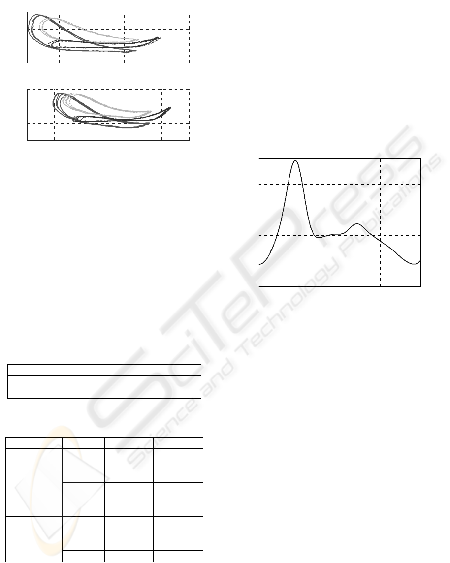
weighting of 68kg and being 1,72m tall. Figure 2
shows the experimental vs. numerical comparison of
right foot marker position during gait on a treadmill,
for the same subject as in Fig. 1.
0 0.5 1 1.5 2
0
200
400
600
800
t[s]
[N]
Experimental results
1.2 1.4 1.6 1.8 2 2.2 2.4 2.6 2.8
0
200
400
600
800
t[s]
[N]
Simulation results
Left foot
Right foot
Right foot
Left foot
Figure 1: Contact forces for a male person. Up:
experimental results; down: results of numerical
simulation.
A MECHATRONIC DEVICE FOR THE REHABILITATION OF ANKLE MOTION
57
0 200 400 600 800 1000
100
200
300
400
x[mm]
y[mm]
Experimental results
-200 0 200 400 600 800 1000
100
200
300
400
x[mm]
y[mm]
Simulation results
Figure 2: Right foot marker position for a male person: a)
experimental results; b) results of numerical simulation.
The comparison of measured vs. simulated results
allows to conclude that the mathematical model is
able to capture correctly the main issues of gait
mechanics and can be hence used to evaluate gait
parameters under conditions that cannot be
physically tested.
After validation, the model was used to derive
quantitative targets for the ankle actuator, taking into
consideration the effect of the Lokomat body weight
support (b.w.s) system. The kinematic targets, not
dependent upon the b.w.s. level, are listed in
Table 1, while torque and power requirements for
different levels of b.w.s. are compared in Table 2.
Table 1: Kinematic targets for the ankle actuator.
MIN MAX
Ankle rotation -10° 20°
Ankle velocity -200°/s 150°/s
Table 2: Torque and power targets corresponding to
different body weight support (b.w.s) levels.
MAX RMS
Torque 112 Nm 54.4 Nm
b.w.s 0%.
Power 152.6 W 48.6 W
Torque 81.6 Nm 43.6 Nm
b.w.s 25%
Power 125.9 W 41.5 W
Torque 65.1 Nm 31.2 Nm
b.w.s 50%
Power 90 W 29.3 W
Torque 31.8 Nm 15.6 Nm
b.w.s 75%
Power 53.8 W 14.5 W
Torque 24 Nm 8.37 Nm
b.w.s 90%
Power 34 W 7.36 W
Measurements described in a companion paper
(Bocciolone et Al., 2008) showed that the Lokomat
body weight support system provides a relief of at
least 85% of patient’s weight. Accordingly, torque
and power targets for the project were assumed in a
precautionary way to correspond to 75% body
weight support.
The target motion of the ankle articulation was
derived based on ELITE measurements (averaged to
remove the intrinsic variability of each step) and on
multi-body simulations. This was made considering
a healthy subject, since the target of the system is to
have the ankle performing a physiologically correct
motion. As an example, the reference time history of
ankle rotation for the same male subject considered
above and for a walking speed of 2km/h is presented
in Figure 3.
0 0.5 1 1.5 2
-5
0
5
10
15
20
t[s]
[°]
Reference motion law - ankle angle
Figure 3: Reference motion law (talo-crural joint) for a
male person.
4 THE CONCEPT
Besides the quantitative performance requirements
resumed in Section 3, a number of qualitative
requirements were defined for the ankle actuator, as
detailed below:
– high intrinsic safety;
– fast and simple installation on the patient’s leg
(wearability);
– low weight, small size and low visual impact;
– low emission of noise and heat;
Furthermore, in case the device is used on a
Lokomat machine, the mounting/dismounting of the
ankle actuator over the Lokomat exoskeleton should
not require any modification of the original
structure.
The concept phase was then divided in two stages:
selection of the type of actuator and design of the
interface with the patient.
As far as the choice of the actuator is concerned,
four alternatives were initially identified:
BIODEVICES 2008 - International Conference on Biomedical Electronics and Devices
58

a) controlled electrical drive with rotating motor;
b) controlled electrical drive with linear motor;
c) controlled pneumatic actuator;
d) controlled Shape Memory Alloy (SMA)
actuator.
These solutions were thoroughly analysed and
compared evidencing for each advantages and weak
points in view of the specific application. The main
results of this comparison are summarized in Table
3.
Table 3: Comparison among main possible solution for the
actuators of device.
Solution
Requirement
Rotating
motor
Linear
motor
Pneumatic
actuator
SMA
actuat
or
Max.
Torque
Good
Very
good
Very
good
Poor
Dynamical
response
Very
good
Very
good
Good Poor
Wearability Good Good Short Fair
Cost Good Fair Fair Fair
Weight and
dimensions
Very
good
Very
good
Poor Good
The electrical drive with a rotating motor (DC or AC
brushless) satisfies all main requirements: it has low
weight and appropriate dimensions, affordable cost
and simple structure which allows to build a device
with a good wearability. Finally, a quite wide variety
of solutions (in terms of size and specific features) is
available on the market, allowing to tailor the choice
in view of the requirements of the specific
application. The drawback of this solution is the
need of using an epicycloidal gear reducer, because
rotating motors present high speed and low torque,
while for ankle actuation, mechanical power is
needed in the form of a relatively high torque acting
at relatively low speed. The use of a gear reducer
implies an increase in the weight of the device,
which can be however kept within reasonable limits.
The linear motor mainly has the same advantages
of the rotating motor and does not bear the drawback
of using a gear reducer, because linear motors
provide relatively high force at low speed, but is
much more expensive than rotating motors, requires
a more complicate mechanical design of the system
and less alternatives are offered on the market.
Pneumatic actuation was considered also
referring to previous applications to ankle actuation:
(Sawicki, 2005) and (Ferris, 2005) showed that this
kind of actuation is able to reproduce with good
accuracy the features of actual ankle motion. In view
of the aims of this project however, this solution
compared to electromechanical solution provides
lower actuation speed, lower maximum control force
and requires auxiliary systems of relatively large
size and potentially disturbing, like the air
compressor.
The SMA actuator solution was also considered
based on some tentative applications in the bio-
medical field, including a parallel project within the
HINT research project. However, besides some
practical disadvantages like the need for a rather
complicated cooling system, present SMA actuation
technology appears to suffer from an insufficient
dynamical response which is not able to ensure the
required actuation speed to implement ankle motion
control.
Based on the analysis summarized above, the
solution based on rotating electric motor was
identified as the most appropriate in terms of
technical requirement and related costs and was
chosen for development. In particular, a 150 W DC
motor (MAXON RE40 150W), driven by a 4-Q-DC
servoamplifier (MAXON ADS 50/10) and coupled
with an epicycloidal gear reducer with a gear ratio of
1:113 (MAXON GP 52C) was chosen.
The second stage of the concept development
consisted in the design of the interface between the
actuator and the leg. The basic idea underlying this
activity was to implement a configuration similar to
the one used in the Lokomat machine. On that
device, the feet are restrained by a sling held by an
arm rigidly connected to the exoskeleton (Figure 4).
The concept for interfacing active ankle actuation
with the patient’s leg was then based on the idea of
replacing the passive arm with an articulated
mechanical system, properly connected with the
motor, so that ankle actuation may be obtained by an
appropriate movement of the final link in the
articulated system. The functional scheme of the
solution identified is reported in Figure 5a: a support
is fixed over the Lokomat exoskeleton, and
connected by a hinge with a link which is actuated
by a crank fitted on the gear output shaft. The
rotation of the link produces a vertical motion of the
sling holding patient’s foot, which can be suitably
controlled by the electric motor. Figure 5b shows a
3D rendering of the ankle actuator, including
motor+gear, crank, link and connection to the
Lokomat exoskeleton.
As shown in Figure 6, the mechanism has a gear
ratio between the rotation of the gear output shaft
and the rotation of the link which is almost constant
and equal to 1:2.5. Figure 7 shows a picture of the
developed device.
A MECHATRONIC DEVICE FOR THE REHABILITATION OF ANKLE MOTION
59
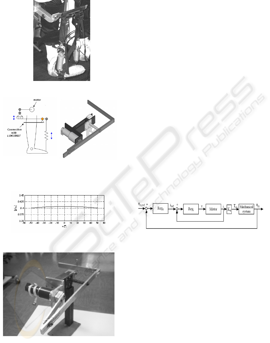
Figure 4: Passive sling of LOKOMAT.
(a) (b)
Figure 5: a) Concept of active ankle actuation; b)
Mechanical design of the ankle actuator.
Figure 6: Gear ratio of kinematic mechanism versus angle
of crank α.
Figure 7: The developed device.
5 CONTROL DESIGN
A relevant part of the research consisted in the
design of the control system for the electro-
mechanical ankle actuator. A typical control
architecture for electrical motors is composed of an
internal feedback loop (called current loop) and an
external feedback loop which in this case was
defined to control the angular position of the motor
(position loop), as shown in Figure 8. This
configuration enables to increase the performances
of the control system and to control at any time the
electrical motor current in order to avoid working
condition potentially dangerous for the electrical
actuator.
The current feedback loop is implemented by the
servoamplifier, which has a very high dynamic
response. Control parameters for the current loop are
optimised by the manufacturer, so it was decided to
use it without any modifications. On the other hand,
the regulator for the position loop was implemented
using a programmable control board (DSP board).
The inputs for the DSP board are the reference
position signal and rotor position measured by an
encoder, whereas the output of the position regulator
is the reference current signal, which is fed into the
current regulator.
Figure 8: Block diagram of control system.
In order to define the reference signal for the
position regulator, first of all a typical wave shape
for ankle angular motion was derived taking into
account the patient’s anthropometry, by means of
numerical simulations supported by measurements,
as described in section 3. Figure 3 shows an example
of reference motion law for ankle rotation.
Then, under the simplifying assumption of having a
constant gear ratio between the output shaft of the
gear and the ankle, the reference for ankle rotation
was converted into a reference for the angular
position of the motor.
In this first stage of study, a proportional-
derivative (PD) regulator has been used for the
design of the position loop. The gains of regulator
were chosen to provide a good performance of
control system and to assure a good dynamic
BIODEVICES 2008 - International Conference on Biomedical Electronics and Devices
60

response. For the optimal design of the regulator, a
simple linear model of the ankle actuator was
defined. The model equations are:
e
dt
di
LiRv ++⋅=
me
Ke θ⋅=
iKT
tm
⋅=
(1)
n
)t(T
TJ
c
mtotm
*
−η=θ⋅
(2)
where v and i are respectively the voltage and the
current of electrical motor characterized by a
resistance R and an inductance L, e is the
electromotive force, K
e
and K
t
are respectively the
speed and torque constants, T
m
is the torque of
motor, J
*
is the equivalent moment of inertia of all
parts of device,
θ
m
is the angular rotation of motor,
η
tot
is the coefficient of efficiency of the reducer, T
c
the resistant torque and n the total gear ratio.
For the control design, the resistant torque T
c
is
considered as a known noise input signal and for this
reason it’s not considered during the design of
regulator.
Finally, numerical tests were performed to verify
the correct tuning of the gain parameter for the
position regulator, using the more detailed non-
linear model described in section 6.1.
6 SIMULATIONS AND TESTS
FOR FINAL ASSESSMENT
6.1 Multi-physics Simulations
A multi-physics model of the ankle actuator was
established, to verify the correct design of the
system (including the regulator) and to assess its
overall performances. The model is composed of:
– an electro-mechanical component, representing
the electrical motor and the gear (see Fig. 9a);
– an electronic component, reproducing the control
loops implemented in the motor drive (Fig. 9a);
– a multi-body biomechanical component, repre-
senting the lower limb and the mechanical
linkages connecting the motor with the foot
(Fig. 9b).
Contrarily to the simplified model used to perform
the control design stage of the project, the multi-
physics model used for verification and assessment
is fully non-linear and accounts for the interaction
effects between the different components of the
system.
In particular, the linear equation (2), representing in
a simplified way the mechanical component of the
system, is replaced by a non-linear equation for the
gear and by a fully non-linear model of the leg and
of the mechanical linkages.
As far as the gear is concerned, a non-linear
formulation is used, accounting for the different
expression of power dissipation in the gear
depending on the power flow being directed from
the motor to the output shaft or vice-versa (Hannah,
Hiller, 1995), so that having defined the mechanical
power flowing in the gear from the motor to the
output shaft W
g
according to the following
expression:
(
)
mmmmg
JTW
θθ
−=
(3)
the mechanical equation of the motor takes the
following non-linear expression:
0for
0for
2
2
<
⎟
⎟
⎠
⎞
⎜
⎜
⎝
⎛
+=+
>
⎟
⎟
⎠
⎞
⎜
⎜
⎝
⎛
+=+
gm
cr
m
cr
m
gm
c
md
c
md
W
n
J
J
n
T
T
W
n
J
J
n
T
T
θ
ηη
θηη
(4)
where J
m
is the moment of inertia of the rotor and
gear input shaft, J
c
is the moment of inertia of the
gear output shaft,
η
d
and
η
r
are the efficiency
coefficients of the gear (for other symbols, see
Section 5).
The leg and the linkages in the ankle actuator are
represented by a multi-body model with an excess of
30 states defined in ADAMS/LifeMOD environ-
ment. The model takes as input the rotation of the
gear output shaft
θ
c
defined as:
mc
n
θ
θ
=
(5)
and by solving the direct dynamic problem for the
linkages and leg returns the motion of the modelled
bodies and the value of the resistant torque T
c
, which
is fed back into equation (4). The use of the non-
linear multi-body model allows to represent in full
detail the actual non-constant gear ratio of the
linkage (see Figure 6), and to take into account the
effect of actual loads (e.g. contact forces exchanged
in the footprint) in the calculation of the resisting
torque T
c
, avoiding the simplifying assumptions that
were introduced for control design purposes.
The model was implemented in Matlab/Simulink
environment, using co-simulation with ADAMS to
account for the coupling between the electro-
A MECHATRONIC DEVICE FOR THE REHABILITATION OF ANKLE MOTION
61
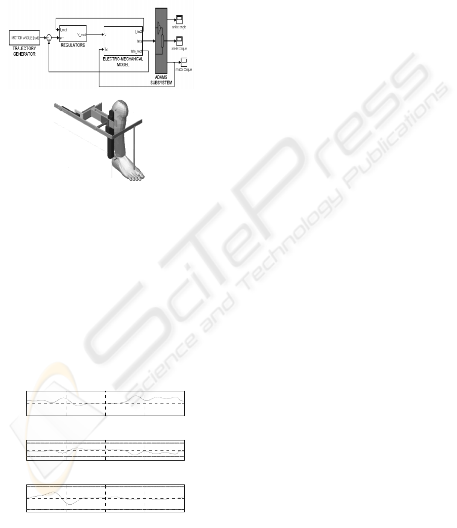
mechanical and electronic components of the model
(implemented in Simulink) and the bio-mechanical
model component (implemented in ADAMS).
Figure 9a shows a high-level representation of the
complete Simulink model, where co-simulation with
the ADAMS subsystem is represented.
(a)
(b)
Figure 9: a) Co-simulation model; b) detail of ADAMS
subsystem.
Figure 10 shows the results of a simulation
reproducing the behaviour of the ankle actuator
under the reference motion law shown in Figure 3
and considering 75% of body weight support. In the
upper subfigure, the deviation of motor rotation with
respect to the reference value is plotted: it is
observed that the maximum deviation is in the range
of 0.3%, indicating that the design of the regulators
was performed correctly, so that the actuator is able
to track position reference within accuracy levels
that are fully satisfactory for the considered
application.
0 0.5 1 1.5 2
-0.5
0
0.5
ankle angle error
t[s]
[%]
0 0.5 1 1.5 2
-5
0
5
motor current
t[s]
[A]
0 0.5 1 1.5 2
-50
0
50
motor voltage
t[s]
[V]
Figure 10: Co-simulation results.
In the central and lower subfigures of Figure 10,
motor voltage and current are plotted, together with
their respective limit values that cannot be exceeded
to prevent damage and ensure durability of the
motor. It is observed that for both voltage and
current the maximum values achieved during the
simulation are well below the limit values,
demonstrating the correct dimensioning of the motor
and actuator for the considered application.
In order to quantify the further ability of the
device to withstand higher working loads (produced
e.g. by unforeseen additional disturbances or by
uncertainties in some design parameters), safety
factors can be defined for voltage and current as the
ratio between the limit value and the actual
maximum absolute value of each quantity. For
motor voltage, the safety factor is 1.70 whereas for
motor current the safety factor is 1.32. These values
are high enough to ensure the robustness of the
system, but not so high to suggest the over-
dimensioning of the motor.
6.2 Tests on a Demonstrator
Preliminary tests were performed on the physical
demonstrator shown in Figure 7, to assess
experimentally the performances of the device. At
the present stage of the research, the demonstrator is
not yet connected to the patient’s leg, so passive
masses are used to produce a resisting torque and
inertial effect reproducing in first approximation the
connection with the ankle.
In this section, three working conditions are
considered:
a) An unloaded condition, which means that no
external or inertial load is applied on the ankle
actuator;
b) A loaded condition obtained by connecting a 5kg
mass to the extremity of the sling, thus
introducing a resisting force of about 50N and an
additional inertial effect;
c) A loaded condition realised through a 10kg
mass, producing a resisting force of about 100N
and an inertial effect higher than in case b).
Tests were performed on the ankle actuator by using
the reference ankle rotation represented in Figure 3
and measuring the actual motor position and the
motor current.
Figure 11 shows the results obtained for working
condition c) in the list above, corresponding to the
most loaded condition. It is observed that the
positioning error is always below 2%, which is a
quite low value but still higher that the one obtained
from the numerical simulation. This result could
however be affected by some electrical noise
disturbance in the measure of the motor angular
BIODEVICES 2008 - International Conference on Biomedical Electronics and Devices
62
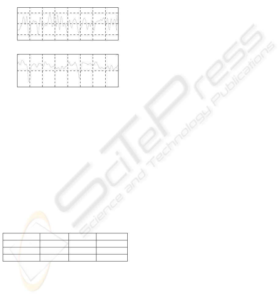
position, so that the actual positioning error could be
in the same range of values as the one obtained by
numerical simulation. More accurate tests are
planned in order to clarify this point.
The motor current is quite low, with maximum
value below 1A, to be compared with a limit value
of 3.33A. This means that there is a large margin for
further loading of the actuator.
0 0.5 1 1.5 2 2.5 3 3.5 4
-2
0
2
ankle angle error
t[s]
[%]
0 0.5 1 1.5 2 2.5 3 3.5 4
0
0.5
1
motor current
t[s]
[A]
Figure 11: Experimental result in 100N load condition.
Up: position error; down: motor current.
Table 4 compares the results of tests performed in
working conditions a) to c), in terms of maximum
angular position error of the motor and of maximum
and r.m.s. value of the motor current required by the
actuator. The maximum position error in the
unloaded condition is much higher than in the two
loading conditions. This is produced by the effect of
plays that are present in the mechanical parts
connecting the final link with the gear output shaft.
The effect of plays is otherwise eliminated by the
presence of the gravitational load applied by the
masses in working conditions b) and c).
Table 4: Values of maximum ankle angle error, maximum
motor current and RMS motor current in different loading
condtions.
Error
max
I
max
I
RMS
No load 5.12% 0.42A 0.1A
50N load 1.95% 0.71A 0.59A
100N load 2.55% 0.82A 0.64A
Considering a different working condition where the
ankle actuator is connected with the patient’s leg, the
effect of plays can seriously affect the performances
of the system, and therefore a new stage of the
research was started to find an alternative design for
the connection between the gear output shaft and the
final link moving the patient’s foot. A solution based
on the use of toothbelt was developed and is
presently under realisation. This new solution is
expected to improve substantially the performances
of the device in actual working conditions.
7 CONCLUSIONS
The paper has reported some results from an
ongoing research having as objective the
development of an electro-mechanical ankle actuator
for use in the rehabilitation of lower limb motion in
patients suffering neurological disease.
Preliminary results obtained by numerical
simulation and tests show the ability of the
developed system to actuate ankle motion within
accuracy levels that are appropriate for rehabilitation
purposes. Research is on going on introducing this
device in physiotherapy. Preliminary test on healthy
and diseased subjects are foreseen in a short time.
ACKNOWLEDGEMENTS
The work presented here was made possible through
the financial support of CARIPLO foundation within
the HINT@Lecco (Health Innovation Network
Technology@Lecco) research project.
REFERENCES
Colombo G, Joerg M, Schreier R, Dietz V., 2000.
Treadmill training of paraplegic patients using a
robotic orthosis. Journal of Rehabilitation Research
and Development 37(6):693-700.
M. Bocciolone, M. Lurati, M. Vanali, F. Molteni. Force
measurement during gait therapy assisted by a robotic
treadmill – The case of Lokomat, proposed as poster
presentation for the BIODEVICES 2008 Conference,
Funchal, Madeira, 28-31 January 2008.
G.S. Sawicki, K.E. Gordon e D.P. Ferris, 2005. Powered
lower limb orthoses: applications in motor adaptation
and rehabilitation. 9th International Conference on
Rehabilitation Robotics, June 28 - July 1, 2005,
Chicago, IL, USA.
D. P. Ferris, J. M. Czerniecki, B Hannaford, 2005. An
anckle-foot orthosis powered by artificial pneumatic
muscles. Journal of Applied Biomechanics, 21, pp
189-197.
A.M. Sabatini, C. Martelloni, S. Scapellato, F. Cavallo,
2005. Assessment of walking feature from foot inertial
sensing. IEEE transactions on biomedical engineering
52(3):486-489.
J. Hannah, M.J. Hillier, 1995. Applied Mechanics,
Longman scientific &technical Editions.
A MECHATRONIC DEVICE FOR THE REHABILITATION OF ANKLE MOTION
63
