
TOWARDS UML-RT BEHAVIOURAL CONSISTENCY
Kawtar Benghazi Akhlaki, Manuel I. Capel Tu
˜
n
´
on, Juan A. Holgado Terriza
Departamento de Lenguajes y Sistemas Inform
´
aticos, ETSI Inform
´
atica, Campus Aynadamar
Universidad de Granada, 18071 Granada, Spain
Luis E. Mendoza Morales
Departamento de Procesos y Sistemas, Edificio de Matem
´
aticas y Sistemas
Universidad Sim
´
on Bol
´
ıvar, Apartado 89000, Baruta, Caracas, 1080-A, Venezuela
Keywords:
Timed Sequence Diagram, State Diagram, Formal semantics, CSP+T, Timed Traces. Timing Constraints.
Abstract:
Having an objective of achieving a formal characterisation of Sequence Diagrams (UML-SD) as a means for
Embedded Real-Time software systems ( ERTS ) development and validation, this paper introduces a CSP+T-
based timed trace semantics for most concepts of SD. A trace is sequence of events, which gives the necessary
expressiveness to capture the standard interpretation of UML SD. Timed SD (TSD) depict work flow, message
passing and gives a general view of how system’s components cooperate over time to achieve a result. Such
sequence, often called an scenario, also represents a part of the system behaviour and a possible execution of
a state machine. State machines and SD are used as complementary models for describing system behaviour.
1 INTRODUCTION
Embedded Real-Time software systems , such as in-
dustrial control systems or automotive systems, get
progressively more complex. Often, major sources
of the complexity are interactions between the dis-
tributed system components. The Unified Modelling
Language (UML) (Selic and J, 1998) has become the
de-facto standard for modelling systems. The ver-
sion 2.0 (OMG, 2004) of the UML enhances the pos-
sibility of modelling complex and hierarchical inter-
actions. It provides flexible and powerful constructs
and operators to express conditions, parallel execu-
tion, repetition and hierarchy. Sequence Diagrams
(SD) are defined in the UML 2.0 for specifying in-
teraction between communicating objects represented
by lifelines and they are used in a number of differ-
ent stages during ERTS development process. It is
important that the precise meaning of SD is well un-
derstood by all the stakeholders of a system under
development; in other words, there is a need for a
well-defined semantics of SD. Having as objective to
achieve a formal characterization of SD as a means
for ERTS development and validation, this paper in-
troduces a CSP-based timed trace semantics for most
concepts of SD.
2 RELATED WORK
There are several other formal trace semantics inter-
pretations of SD that have been considered before. In
(Haugen, 2005) STAIRS addresses all the operators
to combine fragments of SD with different behavior.
The temporal view of SD is not complemented with
richer timing expressions than the standard UML an-
notations. This approach can be considered comple-
mentary with our work, since our approach tends to
integrate SD with other UML 2.0 analysis artifacts,
such as state machine, in order to yield an integrated
dynamic object-oriented model of an ERTS accord-
ing to the development process proposed in (Capel
et al., 2005). The work of X.Li et al (Li et al., 2004)
presents a formal semantics of SD in the context of
a class diagram that is also formalized. The dynamic
semantics of a conceptual system model is captured
by a classical flat deterministic state machine. By giv-
ing a formal semantics to both SD and state machine,
it can be checked whether an SD realizes a use case
of the system conceptual model. No temporal view
of the SD or the state machine is addressed there.
Other general contributions based on the formaliza-
tion of the dynamic model that describes the behavior
of different types of systems have been carried out in
the OMT’s dynamic model (Cheng, 2002) and UML’s
612
Benghazi Akhlaki K., I. Capel Tuñón M., A. Holgado Terriza J. and E. Mendoza Morales L. (2007).
TOWARDS UML-RT BEHAVIOURAL CONSISTENCY.
In Proceedings of the Ninth International Conference on Enterprise Information Systems - ISAS, pages 612-615
DOI: 10.5220/0002395006120615
Copyright
c
SciTePress
state machine diagrams (Cobben et al., 1998) none
of the above referred, gives an integrated view of the
system under development from the different comple-
mentary views that are used in ERTS development.
This paper considers SD as a formal vehicle to repre-
sent interaction and timing constraints between event
occurrences within the system behavior. An SD can
be interpreted as a set of timed traces which represents
an scenario that captures how a system’s component
behaves over time. On the other hand, to determine
the existence of temporal consistency between differ-
ent system submodels,SD gives a global view of the
system interaction that subsequently allows reasoning
about timing requirements of each component, as well
as taking into account interactions with its environ-
ment. To demonstrate temporal consistency and to
ease the design of state machine we propose a sys-
tematic transformation from timed sequence diagram
to timed state machine that extends the set of transfor-
mation rules given in (Benghazi et al., 2007) in order
to have a unique representation of timing constraints
that facilitates the detailed design and further imple-
mentation of an ERTS.
3 TIMED SEQUENCE DIAGRAM
SEMANTICS
3.1 Static Semantics
A Timed UML sequence diagram is a tuple SD =
(O, M, TC), where:
O is a finite set of objects
M is a finite set of messages M = (O
s
, O
re
, m,t
s
,t
re
);
With, O
s
is the sender objects and O
re
is the receiver
objects of the message m ,
t
s
is time of message sending and t
re
is the time of the
message reception with t
s
< t
re
TC is a set of timing constraints d
i
corresponds to the
passing message duration.
3.2 Dynamic Semantics
A UML sequence diagram has two dimensions: the
vertical dimension represents time, and the horizontal
represents different objects. Each object is assigned
a column, the messages are shown as horizontal la-
belled arrows. The dynamic semantic of sequence di-
agrams in this paper is interpreted as a trace-based
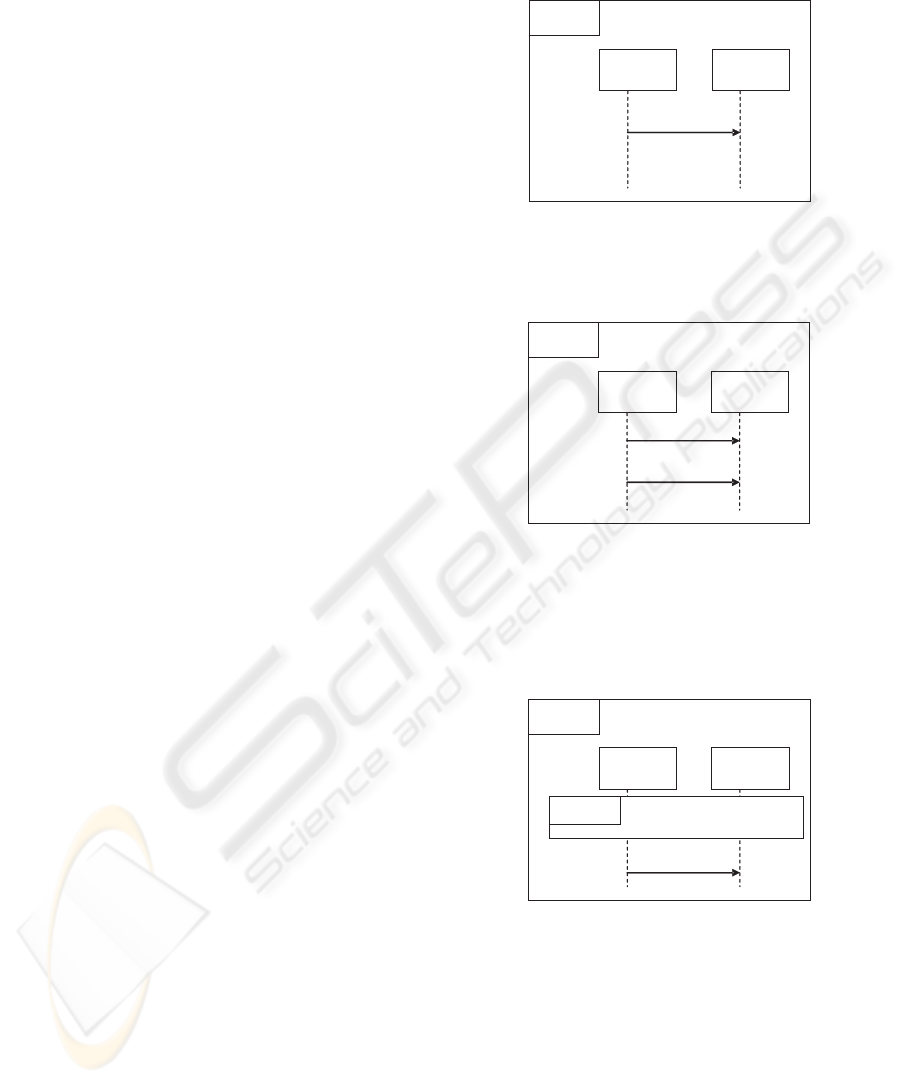
process of CSP+T (Zic, 1994). The interaction of
Fig.1 is almost the simplest interaction there is only
one message from one lifeline to another, the time
of the sending (!m
1
) and receiving event (?m
1
) is
marked by the sending time t
s
and receiving time t
r
respectively.
C1
C2
m1
Sd S0
t
s
t
r
Figure 1: Simple Sequence Diagram.
Fig.1 is represented by CSP+T trace
S0 =< m
1
,t
s1
,t
r1
> =<!m
1
,t
s1
> ˆ <?m1,t
r1
>
C1
C2
m1
m2
Sd S1
t
s1
t
r1
t
r2
t
s2
Figure 2: Message Sequencing.
In Fig.2, after sending m
1
, the component c
1
can
not send any other message until the component c
2
have received it. Thus, t
s2
must be greater than
t
r1
(t
s2
> t
r1
). This is mapped to a CSP+T trace:
S1 =< m
1
,t
s1
,t
r1
> ˆ < m
2
,t
s2
,t
r2
>
C1
C2
m2
Sd S1
Ref S0
t
r2
t
s2
Figure 3: Ref Tag.
Fig.3, is represented by a CSP+T trace:
S1 = S0ˆm
2
=<!m
1
,t
s1
> ˆ <?m
1
,t
r1
>
ˆ <!m
2
,t
s2
> ˆ <?m
2
,t
r2
>
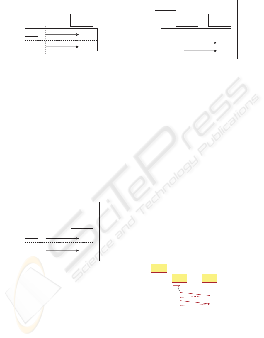
Fig4, shows how the conditional execution in UML
2.0 is presented using a tag alt and diving the body
of the control into multiples subregions by horizontal
dashed lines. Only the messages of one of the subre-
gions can be executed. This SD represents the behav-
ior defined by the union of the sequence trace of both
TOWARDS UML-RT BEHAVIOURAL CONSISTENCY
613
C1
C2
m1
m2
Sd S2
alt
t
s1
t
r1
t
r2
t
s2
Figure 4: Alternative Sequencing.
subregions. Fig4 is mapped to the trace sequence :
S2 = m
2
|m
1
=< m
1
,t
s1
,t
r1
> | < m
2
,t
s2
,t
r2
>
= (<!m
1
,t
s1
> ˆ <?m
1
,t
r1
>)|(<!m
2
,t
s2
>
ˆ <?m
2
,t
r2
>)
The above operator must be understood as an ex-
clusive or. The tag par represent the parallel execu-
tion where the body of the control operator is divided
into multiple subregions by horizontal dashed lines,
each subregions represents an individual computation
that interleaves its events and actions. When the con-
trol operator is entered, all of the subregions execute
concurrently. Concurrency is should be interpreted
here as indistinguishable from non-determinism. The
execution of the message in each subregion is sequen-
tial, but the relative order of messages in parallel sub-
regions is completely arbitrary.
C1
C2
m1
m2
Sd S3
par
t
s1
t
r1
t
r2
t
s2
Figure 5: Parallel Execution.
This semantics is given in CSP+T by:
S3 = (<!m
1
,t
s1
> ˆ <?m1,t
r1
>)ˆ
(<!m
2
,t
s2
> ˆ <?m
2
,t
r2
>) ∨ (<!m
2
,t
s2
>
ˆ <?m
2
,t
r2
>)ˆ(<!m
1
,t
s1
> ˆ <?m
1
,t
r1
>)
In Fig.6, we introduce another construct called itera-
tive execution, represented by a loop tag; the body of
the loop is executed n times, repeatedly.
The semantics of this operator in CSP is given by:
S4 = (m
1
ˆm
2
)
n
= (<!m
1
,t
s1
> ˆ <?m
1
,t
r1
> ˆ <!m
2
,t
s2
> ˆ <?m
2
,t
r2
>)
n
C1
C2
m1
m2
Sd S4
Loop n
t
s1
t
r1
t
r2
t
s2
Figure 6: Parallel Execution.
4 SOUNDNESS WITHIN
TEMPORAL CONSISTENCY
State machine and sequence diagrams have been
widely used in RTS design. State machine are used
for describing the behavior of each component. On
the other hand, a sequence diagram shows possible
interactions between components, it is a structured
representation of components behaviour as a series of
sequential steps over time. It is used to depict work
flow, message passing and gives a general view of
how components cooperate over time to achieve a re-
sult. Such sequence, often called a scenario, also rep-
resents a part of the system behaviour and a possible
execution of a state machine. State machine and SD
are used as complementary models for describing sys-
tem behaviour.
Setting up a correct system requires to guarantee the
temporal consistency of its specification. A SD gives
a general view of the interaction between compo-
nents. Hence, it can be used as a tool to schedule
the message passing as well as time restriction over
time between each system components and its envi-
ronments.
How the timing Constraints are established in a se-
quence Diagram:
A B
m
1
,d
1
m
2
,d
2
t
1
t
2
t
3
>t
1
+d
1
+d
ack
t
4
>t
2
+d
ack
t
0
d
ack
d
ack
T
0
Sd seq
Figure 7: Timed Sequence diagram.
1. The origin of time in each lifeline is marked by
capturing the time occurrence of the first event re-
ception in a sequence diagram lifeline.
2. Within an interaction between two components:
the sender transmits a message and it suspends
ICEIS 2007 - International Conference on Enterprise Information Systems
614
until it receives an acknowledgment from the re-
ceiver.
3. Each message m sent between two components
has a time duration d, which refers to the time
(a) Thus, The time of receiving event (t
re
) must be
greater than a time of the sending event t
s
. t
re
=
t
s
+ d & t
re
> t
s
.
(b) while the interval t
s
< t ≤ t
s
+ d + d
ack
≡ I(d +
d
ack
,t
s
) lasts, the sender remains suspended.
Hence, in this time interval the sender can not
engage in any other communication, i.e., either
sending or receiving any events.
4. In the interval I(d
ack
,t
re
) the receiver(component
B) can not accept to establish any other communi-
cation through the port P
2
.
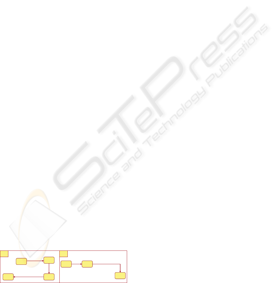
By transforming SDs to state diagrams we guar-
antee that the time constraint specified in SD are re-
ally met by the state machine associated to the com-
ponents in that SD . A sequence diagram implying
N objects are transformed systematically into N ob-
jects state machine, when we transform a sequence di-
agram into a set of timed traces and the state machine
into a set of processes applying the rules established
in our previous work (Benghazi et al., 2007) and then
to set of timed traces, we can prove and therefore, to
prove the consistency between both diagrams as well.
In the timed sequence diagram Fig.7 the message
m
0
, initializes a system, t
0
, mark the time origin of
the system and T
0
represents the initialization dura-
tion. Thus, the sending time of the first message m
1
sent by A must be greater to t
0
+ T
0
, this constraints
is represented in state machine as the specification in-
terval by the CSP+ T term, I(T, t
0
+ T
0
) → !m
1
.The
sending time or reception time of the next message
m
2
must be greater than t
1
+ d + d
ack
, which is the
time of the rendez-vous termination, with d the time
duration between the sending and the reception event.
These constraints are imported to the state machine
as CSP+ T statements: I(T,t
1
+ d + d
ack
) →!m
2
and
I(T,t
2
+ d
ack
). see Fig.8
?m
o
><t
0
\ I(T
o
, t
0
)→ !m
1
\ I(T,t
1
+d
1
+d
ack
)→ !m
2
A
?m
o
><t
0
\ I(T
o
, t
0
)→ !m
1
\ I(T,t
1
+d
1
+d
ack
)→ !m
2
A
?m
1
><t
2
m
2
[I(T ,t
2
+d
ack
) ]><t
4
B
?m
1
><t
2
m
2
[I(T ,t
2
+d
ack
) ]><t
4
B
Figure 8: Communicating Extended State machines.
5 CONCLUSIONS
One aim of this work is to assign a precise meaning to
component interactions that arise in standard UML-
RT diagrams, such as the SD ones. We have firstly
given a timed trace semantics with CSP+T annota-
tions to UML 2.0 SD and then a set of transforma-
tion rules, which allows to check behavioural consis-
tency between SD and state machine. The systematic
derivation of state machines from a SD can be also
obtained as another product of our technique. Vali-
dation techniques based on systematic checking, like
temporal consistency checking can be addressed with
our approach as well. The long vision of our work is
to integrate the timed SD into our RTS development
methodology proposed in previous works (Benghazi
et al., 2007); thus, we plan to use the SD in differ-
ent phases, i.e., analysis, design and verification of a
system development cycle.
REFERENCES
Benghazi, K., Capel, M. I., Mendoza, L. I., and Holgado,
J. A. (2007). A methodological approach to the for-
mal specification of real-time systems by transforma-
tion of uml-rt design models. In Science Computer
Programming. Elsevier.
Capel, M., Benghazi, K., and Holgado, J. (2005). Combin-
ing the description features of uml-rt and csp+t spec-
ifications applied to a complete design of real-time
systems. In IJIT, Information Journal of information
Technology.
Cheng, H. C, E. Y. (2002). Uml for modelling complex
real-time systems. In Software Eng. IEEE Trans. 28.
Cobben, M. H., Engels, A., Mauw, S., and Reniers, M. A.
(1998). A semantic formalization of uml-rt models
with csp+t processes applicable to real-time systems
verification. In Formal Semantics of Message Se-
quence Charts.
Haugen, Knut Eilif Husa, R. K. R. K. S. (2005). Stairs to-
wards formal design with sequence diagrams. In Soft-
ware and System Modeling.
Li, X., Liu, Z., and He, J. (2004). A formal semantics of
uml sequence diagrams. In IEEE Computer Society.
ASWEC’2004.
OMG (2004). Super structure specification. In Software
Eng. Object Managment Group.
Selic, B. and J, R. (1998). Uml for modelling complex real-
time systems. In ObjectTime.
Zic (1994). Timed constrained buffer specifications in csp +
t and timed csp. In ACM Transaction on Programming
Languages and Systems.
TOWARDS UML-RT BEHAVIOURAL CONSISTENCY
615
