
SYNCHRONIZATION ISSUES IN UML MODELS
Marco Costa
INESC-ID / Univ. Lusíada, Lisbon, Portugal
Alberto Rodrigues da Silva
INESC-ID / Instituto Superior Técnico, Lisbon, Portugal
Keywords: Synchronization, Models, QVT, UML, Traceability, Transformations.
Abstract: Information systems have been changing regarding not only technologies but also notations and
methodologies till now. As the complexity of the implemented systems is growing steadily, the need for
ways of systematically develop applications increase. A multitude of tools appear to help in the
development process. Tools are supporting and generating a large number of artefacts but development
teams still have a difficult task: how to manage the coherence of that information in a context of highly
dynamic changes. We discuss some important questions regarding synchronization, not only traceability,
namely how to develop a fully customizable and extensible application in this field, which will instantiate a
new class of applications.
1 INTRODUCTION
Information systems have been changing regarding
not only technologies but also notations and
methodologies. As the complexity of the
implemented systems is growing steadily, the need
for ways of systematically develop applications
increase. Cost and time, as well as quality, were
obvious factors for creating methodologies to
develop and maintain this kind of systems. A
systemic approach was followed and the most part
of the used methodologies accepted the fact that
models are an important conceptual tool to
understand complex information systems. The
model driven development (MDD) has its roots on
the methodologies boom of the 1970s and 1980s
(Jackson, 75; Martin, 89). During the 1990’s the
existing notations where gradually replaced by UML
(Unified Modelling Language) that emerged as an
OMG standard (OMG, i). Meanwhile UML has been
upgraded from versions 1.0 to 1.5 and now 2.0.
Today it is being recognized as the most used
standard notation for information systems design.
This tendency is clearly beneficiating the CASE
tools market reviving it again (Welsh, 2003).
Currently, this kind of tools have gained acceptance
again in the development teams and once again there
are many products competing. Features like code
generation are important assets for CASE tools
(Herrington, 2003), especially if they want to
support the MDA (Model Driven Architecture)
approach.
Still, it is important to identify the current
difficulties with the use of CASE tools. The
methodological know-how is now more known, the
development processes requires CASE tools and the
product prices are more reasonable now than before.
So, why many development teams are still using
CASE tools just for documenting the projects early
phases? The documentation aspect of using CASE
tools is obviously important, but this is not the only,
or even the most relevant feature. One known
difficulty in introducing CASE tools in existing
projects is the “not enforced“ factor (Iivari, 1996). In
projects where these tools are not enforced in the
software process, developers tend to use other tools
as well. Consequences of this approach are currently
seen in many projects: inconsistencies between
documentation and code, different definitions of
concepts in modules of the same application
resulting in compromised subsequent development.
In practice, some of the original goals of CASE tools
are still not achieved. For example, they don’t
eliminate inconsistencies, redundancy or yet don’t
provide correct project documentation when the
project is in the maintenance phase and changes are
made to the initial model.
607
Costa M. and Rodrigues da Silva A. (2007).
SYNCHRONIZATION ISSUES IN UML MODELS.
In Proceedings of the Ninth International Conference on Enterprise Information Systems - ISAS, pages 607-611
DOI: 10.5220/0002393606070611
Copyright
c
SciTePress
In our work we propose a new approach to
synchronize all artefacts involved in the
development process, even when generated or
supported by different tools. We defend the
importance of the synchronization approach as vital
to the future success of the MDA tendency.
Regarding this and the large number of technologies
involved, we propose in this paper a synchronization
model presented and discussed through an
application prototype.
Nowadays, there are several related proposals on
transformations between models, and between
models and code, that we make reference of. The
main focus of this work is not on the transformation
techniques, already studied in other works. Instead
we define what we think must be synchronization
between artefacts and several types of relations wich
should be considered.
2 ARTEFACTS AND
SYNCHRONIZATION
Artefacts are work products generated or crafted by
tools used in some development process, e.g.
diagrams, textual descriptions and code. In complex
projects that deal with several different operating
environments, database management systems, and
interactions with other applications the number of
artefacts can be considerable. The complexity in
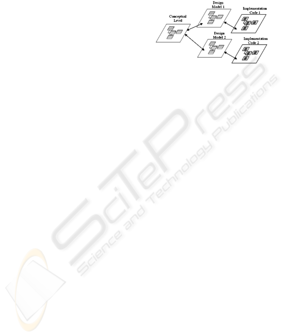
interactions can be illustrated by a simple example:
Let us consider an application with one hundred
business model classes, two different
implementation platforms (like .NET and J2EE),
they have to be translated to two hundred or more
design classes. Of course the real implementations
have at least another two hundred classes, in one or
more programming languages. If the application has
to access a relational database management system,
as well as other data files, the generated overflow
will be even greater. Fig. 1 illustrates this simple
scenario.
With this very basic example we see that classes
at different contexts can be also different
representations of the same concepts. Five hundred
or more classes can be one hundred concepts that
need to be maintained, as the application evolves
over time. All this classes are part of the solution,
not just the implementation ones. Iterative
development, which produces artefacts in some
known sequence, is very common nowadays.
Usually this kind of process regenerates some parts
of the system, protecting the previous specific work
of being deleted. Code generation and/or model
transformation are used for achieving this and there
are already many CASE tools able to generate code
for the most used programming languages. Code, as
already defined, is just a type of artefact in the
development process.
Figure 1: Simple relation between models and code.
However there are specific tools that deal with this
type of artefacts, namely, IDE (Integrated
Development Environment), specific editors or code
optimizers. Reverse and round-trip engineering are
limited features in the current available tools. Even
when they exist, the ways of achieving those
features are tool dependant. Each tool has its own set
of capabilities regarding code generation, from the
simple class model to code (as used in Visual Studio
.NET) to models to models (as used in Codagen).
Even when tools achieve some type of
transformation, each one has it’s own workflow that
may not allow some kind of interaction with other
transformation tools. OMG’s QVT (Queries, Views
and Transformations (OMG, 2005)) is aimed to
standardize not only transformations between
models, which is the main objective, but also other
operations with models like queries and views. As
new QVT compliant products arrive we see
transformations being used more often but the
problem of artefact synchronization, as defined in
our work, is not directly addressed by the standard.
In the next section we introduce a way of describing
synchronization, from a practical viewpoint.
3 DEPENDENCY RELATIONS
Before we define synchronization we must describe
some basic relations between model elements. Let us
define the equivalence relation between two
elements of a model, or from different models, as
when they have the same representation of the same
concept. In this context same representation stands
for having the same data that identifies the concept
in different views, or representations, of a concept.
In Figure 2 there are three different cases to
illustrate elements equivalence, or by extension,
models equivalence.
ICEIS 2007 - International Conference on Enterprise Information Systems
608
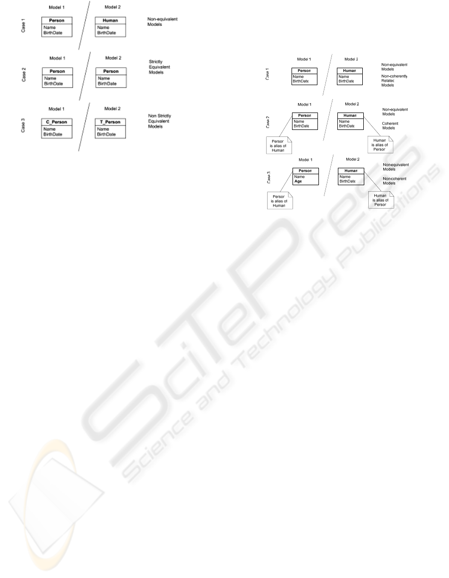
Figure 2: Two different types of equivalence between
models/elements.
In the first case the two representations have
different names so the elements are considered non-
equivalent. This is a very restrictive relationship
between elements. We can extend the relation of
equivalence to models saying that for two equivalent
models M1 and M2:
∀e
1
i
∈ M
1
∃
1
e
2
i
∈ M
2
: e
1
i
⇔
e
2
i
∧
∀e
2
i
∈ M
2
∃
1
e
1
i
∈ M
1
: e
2
i
⇔ e
1
i
(1)
It is relevant to distinguish the equivalence
relation from the identity relation. Two elements are
considered identical if they have the same
representation of the same concept in the same
context. In Fig. 1 the two models can be at different
conceptual levels (e.g., Model 1 can be the domain
model and Model 2 can be the design model).
Identity is obviously more restrictive than
equivalence because it guarantees the same context
to both elements/models, not just the same
representation and concept. The identity between
elements is usually well addressed in the existent
CASE tools, so when someone modifies a graphical
element usually all the views of that element are also
updated elsewhere in other diagrams that use it.
The third case distinguishes between strict and
non strict equivalence. If there is some kind of rule
that systematically changes the identity (or other
concept data), in two different contexts, than it is
possible to say that two elements are still equivalent,
even if not strictly.
In the first case, with the provided information, we
can’t say that the two classes are representations of
the same concept, even if it can be intuitively
known. This kind of problem may occur when the
modelled domain is very complex and there is the
need to have alias for some elements in order to get
more expressivity from the models. In that case we
can say that the two elements are coherent if they are
different representations of the same concept. To
know that there is an identity in concepts between
the two coherent elements there must be some
information showing it. Of course, this information
must be in the model, as we want to visually, as well
as automatically, verify this kind of relation.
Figure 3: Coherence between elements/models.
To illustrate this, in Case 1 of the figure above, the
two classes are not related regarding coherence. We
can’t say if they are coherent or not, since they are
not related by this kind of dependency relation.
In Case 2, with simplified information, was possible
to relate the two classes and turning them coherent,
with information associated to each class. In real
work coherence is more difficult to maintain than
the other two relations. CASE tools are generally
prepared to internally (not graphically) document the
given example with some kind of class properties
but this is probably one of the most usual examples
available. Other coherence relations between
elements can include different types of class
attributes, depending of the context levels (e.g.,
design and programming). Of course, if necessary,
the coherence between two related elements shall be
identified and maintained.
We define synchronization as the activity of
maintaining coherence relations when they exist,
i.e., between all related elements. To be usable, in
real practice, this activity must be supported by
automated tools, even with partial human
intervention.
Relating to the MDA (Model Driven Architecture)
approach we divide artefacts in four levels, each one
having a different conceptual scope (Figure 3).
Synchronization actions can then be classified as:
- Internal synchronization: The set of artefacts
describing the model is coherent. In this case the
model, and by extension his artefacts, are internally
synchronized;
- Horizontal synchronization: The models inside
each level are coherent;
SYNCHRONIZATION ISSUES IN UML MODELS
609
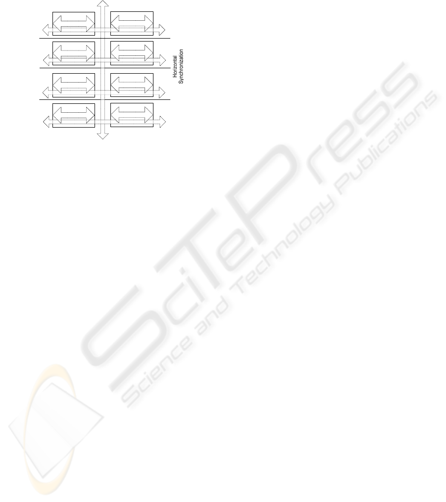
- Vertical model synchronization: Two models of
different levels are coherent;
- Vertical level synchronization: Two levels are
synchronized, i.e., all models of each one are
coherent with the models of the other.
Module 1
Module m
...
PSM Model 1
PSM Model n
...
Code Level
PSM Level
PIM Level
PIM Model 1
PIM Model p
...
CIM Level
CIM Model 1
CIM Model q
...
Vertical
Synchronization
Figure 4: Synchronization dimensions relating with MDA.
To better explain implementation details we can
divide artefacts in two types: models and code.
Synchronization can be also characterized by
artefact type:
- Intermodels: One model is synchronized with
other model;
- Intramodels: Inside one model some elements
can be synchronized;
- Code-model: One or more model elements can
be synchronized with one or more code elements
(e.g., one pattern occurrence like Factory is
synchronized with a group of code classes);
- Code-Code: Two code elements are coherently
related (e.g., one C# class is related with a Java
class).
4 DEFINING A
SYNCHRONIZATION
APPLICATION
To be done, synchronization actions need four
different capabilities from a tool: parsing, transform
between metamodels, coherence exceptions,
traceability and interactivity.
First, the tool must be able to parse data from
different files (which are project artefacts). Data is
not only the models and code that are included in the
project, it can be also metamodels of the different
kinds of models and languages to be deal with. QVT
is very useful regarding this issue as it is possible to
define a metamodel language, graphically and
textually.
The transformations between metamodels are
needed because that is the way to express
systematically a group of transformations. Also it is
necessary to address the coherence issue and that
can be achieved using a collection of exceptions to
the systematic transformations between metamodels.
These exceptions are expressed in terms of the
related metamodels.
Synchronization may be considered a particular
case of traceability in the sense that it is necessary to
maintain links between elements that sometimes
belong to different conceptual levels. But
synchronization also needs interactivity because
changes made to the system may violate the existing
coherence rules. When a change of this kind occurs
some interaction is needed – the application must
know if the coherence rule still holds. The
interaction may be decreased with generic action
rules (e.g., when a table name is changed, and that
table is related to a design class, automatically
change the related name of the design class).
As shown, the coherence relation can be a non
systematic relation. It can be even an exception to
the rules used to transform between models.
The QVT standard does not specify a way of
implementing the traces between objects, but they
are implicitly considered as existing.
5 RELATED WORK
Object Management Group as issued the Meta
Object Facility Queries/Views/Transformations
(OMG, 2005) as the standard for transformations
between models. This specification also defines two
types of approaches to the transformation writing,
namely Relations and Operational Mappings. The
first is a declarative way of expressing queries,
views and transformations. The second is an
imperative approach which may be used to
complement the Relations language.
Software vendors (e.g., Microsoft, Borland,
Sybase) have a particular interest on this problem as
CASE tools or IDE producers. Microsoft Visual
Studio 2005 (Microsoft, 2006) and Borland Together
(Borland, 2006) have already some kind of
synchronization implemented. E.g., it is possible to
see an UML like class diagram representing the
class structure in the source code. Being important it
is not sufficient because we may need several
models in different layers of abstraction representing
MDA’s computer independent models (CIM),
platform independent models (PIM) and platform
specific models (PSM). Not only we want to
generate the lower levels from the upper levels, but
ICEIS 2007 - International Conference on Enterprise Information Systems
610
also maintain the traceability between elements of
each layer. Legacy systems exist and it is necessary
not only to see development cycle from a top-down
perspective but also with integration in mind.
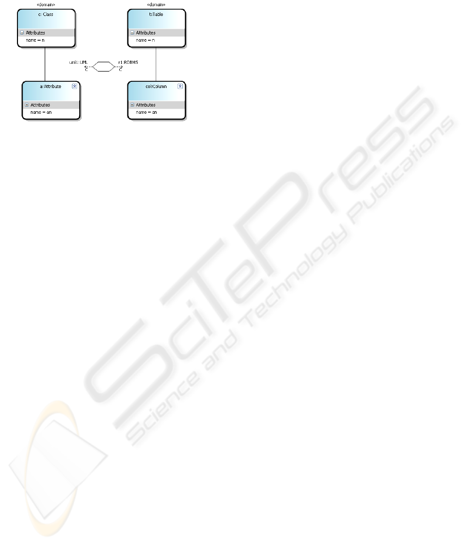
Figure 5: A QVT Relations diagram (made with prototype
application).
With the above referenced tools it is not
possible, for instance, to declare that a class in one
PIM model is mapped to a different named class in
two PSM models that have also different names in
the implemented classes. Other existent tools (e.g.,
Codagen (Codagen, 2006)) focus on automatic code
or models generation. With these tools a part of the
project is automatically generated between phases.
Again this kind of work is necessary but not
sufficient because we need to continually add
changes to different levels and see what impact
those changes have in the overall project.
6 CONCLUSION
The actual variety and proliferation of competing
CASE tools (Baik et al., 2000) may represent a
problem because the produced artefacts have to be
updated along their lifecycles. Notations have been
replaced, programming languages and
methodologies have evolved significantly but, at
large extent, users are still responsible of
maintaining artefacts actualized. Existent tools can
do some kind of synchronization but the ways for
achieving this are tool dependent and with difficult
customization.
The convergence of modelling notations to UML
was an important factor because it gives some
stability to this field. Development teams are still
adopting UML as the notation and practical issues
are emerging with more experience and new releases
of the standard. Synchronization, as defined here,
presents practical difficulties that must be
overridden in order to speed up the application
evolution, especially in large projects. A new class
of tools is necessary, one that could synchronize all
artefacts of the project, using a uniform way of
achieving it. These new tools can be integrated in
existing CASE tools, or operated as standalone
applications. Instead of doing just a predefined set of
synchronizations between code and models, these
tools should perform a user defined set of
verifications and trigger a related set of actions that
will leave the system in a coherent state.
An application prototype was developed wich uses
QVT as its fundamental reference. The application
was implemented using the Microsoft Visual Studio
.NET 2005 Specific Domain Language SDK and is
currently under test.
REFERENCES
Baik, J., Boehm, B., 2000. Empirical Analysis of CASE
Tool Effects on Software Development Effort. Center
for Software Engineering, http://sunset.usc.edu/
publications/TECHRPTS/2000/usccse2000-504/
usccse2000-504.pdf (2000)
Bettin, J. et al., 2003. Generative Model Transformer: An
Open Source MDA Tool Initiative. OOPSLA,
http://www.softmetaware.com/oopsla2003/pos10-
bettin.pdf (2003)
Borland, 2006. Borland Together Technologies,
http://www.borland.com/us/products/
together/index.html
Codagen, 2006. http://www.codagen.com/
Dollard, K.2004. Code Generation in Microsoft .NET.
Apress.
Gardner, T. et al. 2003. A review of OMG MOF 2.0 Query
/ Views / Transformations Submissions and
recommendations towards the final Standard.
http://www.zurich.ibm.com/ pdf/ebizz/gardner-etal.pdf
Herrington, J. 2003. Code Generation In Action. Manning
Pub. Co (2003)
IBM, 2003. MOF Query / Views / Transformations First
revised Submission, http://www.omg.org /docs/ad/03-
08-03.pdf
Iivari, J. 1996. Communications of the ACM. Why Are
CASE Tools Not Used, Oct.1996, Vol.39, Nr.10, Pgs.
94-103, Association for Computing Machinery
Jackson, M. 1975. Principles of Program Design,
Academic Press
Martin, J. 1989. Information Engineering: Introduction,
Prentice Hall
Microsft, 2006. Microsoft Visual Studio Developer
Center, http://msdn.microsoft.com/ vstudio/
OMG: Object Management Group, 2005. MOF QVT Final
Adopted Specification
http://www.omg.org/docs/ptc/05-11-01.pdf
QVTP, 2003. Revised submission for MOF 2.0 Query /
Views / Transformations RFP, Vers. 1.1, QVT-
Partners, http://qvtp.org
Welsh, T., 2003. How Software Modelling Tools Are
Being Used. In Enterprise Architecture Advisory
Service Executive Update Vol. 6, N. 9, 2003-12,
Cutter Consortium.
SYNCHRONIZATION ISSUES IN UML MODELS
611
