
REVISITING THE MARKOV CHAIN MODEL OF IEEE 802.11E
EDCA AND INTRODUCING THE VIRTUAL COLLISION
PHENOMENON
∗
Mohamad El Masri
◦
, Guy Juanole
‡
and Slim Abdellatif
◦
LAAS-CNRS;
◦
INSA,
‡
UPS; University of Toulouse, Toulouse, France
Keywords:
Quality Of Service, Wireless Local Area Networks, Modelling, Markov Chain.
Abstract:
IEEE 802.11e specifies the Enhanced Distributed Channel Access (EDCA) for distributed access with traffic
differentiation to a Wireless Local Area Network (WLAN). Traffic differentiation led to introducing several
traffic queues within each station, thus introducing virtual collision. In this paper, we present a pattern based
Markov chain model of EDCA including the virtual collision phenomenon not found in previous work. We
also correct the misconceptions found in existing Markov chain models of EDCA (Kong et al., 2004). We thus
obtain a more realistic model of IEEE 802.11e EDCA which will allow a more precise performance analysis
that may be used for admission control.
1 INTRODUCTION
The IEEE 802.11e work group (802.11e, 2005) intro-
duced QoS (Quality of Service) mechanisms into the
MAC layer (Medium Access Control) of the legacy
IEEE 802.11 standard. This mainly consisted in the
definition of a new access function: HCF (Hybrid
Access Control) which combines two access modes,
one of these is EDCA (Enhanced Distributed Chan-
nel Access) which is an enhancement of DCF (Dis-
tributed Coordination Function based on a CSMA/CA
scheme). EDCA is the area of interest of our work.
With respect to DCF, EDCA introduces the traffic dif-
ferentiation concept, thus defining four access cate-
gories (AC), each corresponding to a different queue
within the station. A CSMA/CA scheme is imple-
mented by each AC. This scheme is based on the ar-
bitration (characterized by the AIFS parameter (Arbi-
tration Inter Frame Space)) and on the backoff proce-
dure (characterized by the contention window (CW)
and the range [CW
min
,CW
max
]). AIFS and CW play
the same role as DIFS and CW in DCF. The choice
of AIFS and CW allow to prioritize the AC traffic (the
smaller the AIFS and CW, the higher the access prob-
ability). Due to the presence of several queues within
∗
This work is partially funded by both EuQoS and SAT-
SIX projects
a station, EDCA introduces, in addition to real col-
lisions (physical collisions in the channel involving
queues from different stations), a new kind of col-
lisions, named virtual collisions. These latter take
place when at least two queues from the same station
try to access the medium at the same time after their
backoff period. It results in granting the access to the
highest priority queue and penalizing the others (by
widening the CW in the same manner as a real colli-
sion). EDCA involves several complex mechanisms,
those are not always clearly specified thus inducing
a lot of questioning among the people working on it.
The use of formal methods is of great interest to help
the understanding and guide the analysis and the per-
formance evaluation of the protocol. Some models
have already been proposed in the literature (Zhu and
Chlamtac, 2005; Kong et al., 2004; Wu et al., 2006),
models which assume a saturation regime (thus fre-
quent collisions) and which are mainly inspired by
the Bianchi model of DCF (Bianchi, 2000). Zhu and
Chlamtac (Zhu and Chlamtac, 2005) proposed a two
dimensional model of an EDCA AC which considers
neither the virtual collision aspect nor the time elaps-
ing during a transmission on the medium. The model
of Kong et. al. (Kong et al., 2004) captures this lat-
ter aspect (at a cost of a new dimension in the model
- the overall model of EDCA is a three dimensional
76
El Masri M., Juanole G. and Abdellatif S. (2007).
REVISITING THE MARKOV CHAIN MODEL OF IEEE 802.11E EDCA AND INTRODUCING THE VIRTUAL COLLISION PHENOMENON.
In Proceedings of the Second International Conference on Wireless Information Networks and Systems, pages 76-84
DOI: 10.5220/0002149500760084
Copyright
c
SciTePress

discrete Markov chain). However it does not describe
explicitly the virtual collision nor does it represent all
the mechanisms described in the standard (802.11e,
2005; Mangold et al., 2003). Wu et. al.’s approach
(Wu et al., 2006) of the different contention zones is
novel, but the consequences of a virtual collision are
not clearly detailed.
The goal of this work is, based on the model of Kong
et. al.(Kong et al., 2004), to define, in a pedagogical
way, a model of an EDCA AC, as complete as possi-
ble i.e. which integrates all the mechanisms specified
by the standard and which to the best of our knowl-
edge has never been done. This model is introduced
progressively by identifying the main behavioral pat-
terns of the EDCA AC.
The paper, dedicated mainly to a careful modelling,
is organized as follows: first we define a modelling
methodology, we then give the models of the differ-
ent patterns and the global model. We then expose
the formulas, which can be gotten from the model and
which are the basics for performance analysis. A val-
idation of the model in different cases is detailed in
the following section. We then conclude by giving
the perspectives of this work.
2 GUIDES FOR THE
MODELLING
2.1 AC
i
Behavioral View
Access Attempt # (m+h+1)
Retransmission # (m+h)
AIFS + Backoff
Collision # (m+h+1)
Access Attempt # 2
Retransmission # 1
AIFS + Backoff
Collision # 2
Collision # 1
Successful
Transmission
Access Attempt # 1
AIFS + Backoff
Actual Transmission
Attempt
Actual Transmission
Attempt
Actual Transmission
Attempt
Packet Drop
Figure 1: Behavior of an AC
i
.
We give an abstract view of an AC
i
’s behavior
(i ∈ (0, 1, 2, 3) in descending priority order) in fig-
ure 1. The transmission of a packet is implemented
through a series of access attempts. Each is based,
at first, on the sequence of two processes (AIFS and
backoff), defining the medium idleness test before
the actual transmission attempt, and then on the ac-
tual transmission attempt (i.e. the decision to make a
transmission). The result of each actual transmission
is either a successful transmission (following which
the sending of a new packet is considered) or a col-
lision (following which the packet’s retransmission is
considered). Note that on the first attempt we have
CW[AC
i
] = CW
min
[AC
i
]. After a collision situation,
the new value of the contention window is computed
as follows:
CW
new
[AC
i
] = min(2 ∗ CW[AC
i
] + 1,CW
max
[AC
i
]) in
order to try to avoid further collisions. We define m
so that after m transmissions, the value of CW[AC
i
]
is CW
max
[AC
i
], h is the additional number of retrans-
missions needed before reaching the Retransmission
Threshold (R
T[AC
i
] = m+ h). If the retransmission
threshold is reached, the packet is dropped and the
transmission of a new packet is considered. This ab-
stract view highlights the basic patterns for the mod-
elling: AIFS procedure, Backoff procedure, actual
transmission attempt procedure and their results.
2.2 The Basic Patterns
2.2.1 Aifs Procedure
Any transmission attempt starts with the ran-
dom choice of the value of the Backoff Counter
(B
C[AC
i
]) within the current contention window
range [0,CW[AC
i
]] (this value defines the backoff time
which will be used at the end of the AIFS period). The
AIFS procedure consists in the necessity to observe
the medium idleness during the AIFS period. If, dur-
ing the AIFS period (We call A its duration in terms
of time slots), the medium becomes busy, we have the
AIFS decrementing freeze during the medium occu-
pation time (we call N the mean value of this duration
in terms of time slots) after which the AIFS count-
down is reset. At the end of the last slot of AIFS, if
the medium is still idle, two outputs are possible: if
B
C[AC
i
] = 0, the AC will directly attempt a transmis-
sion; if B
C[AC
i
] > 0, the value of B C[AC
i
] is decre-
mented of one, thus initiating the backoff procedure.
2.2.2 Backoff Procedure
A backoff procedure will mainly consist in decre-
menting the value of B
C[AC
i
] while the medium is
idle. The value of B
C[AC
i
] is decremented until it
reaches 0, one slot after which a transmission is di-
rectly attempted if the medium is still idle. If during
REVISITING THE MARKOV CHAIN MODEL OF IEEE 802.11E EDCA AND INTRODUCING THE VIRTUAL
COLLISION PHENOMENON
77

the backoff counter decrementing, the medium be-
comes busy, the decrementing procedure is stopped
and frozen during a time which is the sum of the
medium occupation time and an AIFS period (this
time has the value N + A), if during the AIFS period,
the medium is busy again, the process is repeated. At
the end of the last slot of AIFS, if the medium is still
idle, two outputs are possible: if B
C[AC
i
] = 0, the AC
will directly attempt a transmission; if B
C[AC
i
] > 0,
the value of B
C[AC
i
] is decremented, thus resuming
the backoff procedure.
2.2.3 Actual Transmission Attempt
When an AC
i
decides to initiate a transmission at-
tempt, either it is the only one within the station to
want to transmit, in which case it will directly access
the medium, or there is at least another AC within the
station also wishing to transmit, in which case both
ACs will go into a virtual collision . Within the virtual
collision handler, the AC winner of the virtual colli-
sion (thus accessing the medium) is the higher priority
AC. If AC
i
loses the virtual collision, then the medium
will be accessed by an AC, virtually colliding with AC
i
and having a higher priority. An actual transmission
attempt is followed by three outcomes:
1. The transmission was successful, in which case
AC
i
occupied the medium for a duration ⌈T
s
⌉ (⌈T
s
⌉
is the smallest integer -in time slots- higher than
T
s
the duration of a successful transmission) and
a new packet transmission is then taken into con-
sideration.
2. AC
i
suffered a real collision, in which case AC
i
occupied the medium for a collided transmission
time ⌈T
c
⌉ and the packet may be retransmitted
within the retry threshold limit.
3. AC
i
lost a virtual collision, in which case AC
i
will not occupy the medium, a higher priority AC
within the station will transmit (either suffering
a collision thus occupying the medium for ⌈T
c
⌉
or transmitting successfully thus occupying the
medium for ⌈T
s
⌉). AC
i
’s packet may be retrans-
mitted within the retry threshold limit.
Situations 2 and 3 above define globally, what we call,
the collision situation for AC
i
.
3 AC
I
MODELLING
3.1 Basics for the Modelling
AC
i
Behavior: We represent it by a discrete Markov
chain where the state must be represented without am-
biguity. A state of the discrete Markov chain must
specify both the packet access attempts (we have to
distinguish on one hand the successive attempts and
their corresponding collisions and on the other hand
a successful transmission), the backoff counter (we
have to distinguish on one hand the backoff procedure
where the backoff counter is meaningful and on the
other hand the situations where the backoff counter
is meaningless) and the remaining time to the end of
the different timed actions (AIFS, medium occupancy,
collision, successful transmission). Therefore a state
of the discrete Markov chain is represented by a triplet
( j, k, d) with j representing the state of the packet at-
tempt, k the backoff counter and d the remaining time.
We consider the following values for each of the com-
ponents:
• j: 0 ≤ j ≤ m+h for the successive attempts (j = 0
for the first attempt and 1 ≤ j ≤ m + h for the
following retransmission attempts), each value of
j is associated to all the states of the AIFS pe-
riod before the backoff, the stage of the backoff
procedure where the value of the contention win-
dow CW[AC
i
] is noted W
j
, and the collision situa-
tion; the successful transmission is represented by
j = −1.
• k: 0 ≤ k ≤ W
j
for stage j of the backoff proce-
dure; in the other cases where k is meaningless
we take a negative value for k (different negative
values should be taken, for triplet uniqueness rea-
sons, depending on the situation as we explain af-
ter the specification of the values of d).
• d: 1 ≤ d ≤ ⌈T
s
⌉ for the duration of a successful
transmission of AC
i
or after a virtual collision of
AC
i
(where AC
k
, winner of the virtual collision,
successfully transmits); 1 ≤ d ≤ ⌈T
c
⌉ for the du-
ration of a collision (of either AC
i
or AC
k
winner
of the virtual collision); 1 ≤ d ≤ A for the AIFS
duration; A+1 ≤ d ≤ N +A for the medium occu-
pancy duration occurring during an AIFS period
or during backoff counter decrementing. Note that
⌈T
c
⌉ < ⌈T
s
⌉.
As for each attempt j the AIFS period before the
backoff and the collision situation (in both situations
the backoff counter is meaningless) can have remain-
ing time values which can be identical, it is necessary,
in order to avoid state ambiguity, to distinguish these
states by a different negative value of k; we choose:
k = −1 for the collision situation and k = −2 for the
AIFS period. The value of k for the successful trans-
mission period is not problematic because of the dif-
ferent value of j, we thus choose k = −1.
Transition probabilities: Before defining the dif-
ferent pattern models forming the whole model, we
must define the probabilities that will be associated to
WINSYS 2007 - International Conference on Wireless Information Networks and Systems
78
the transitions. At first we define the following basic
probabilities:
• The probability related to the fact that the medium
is busy (p
b
) or not (1− p
b
).
• The probabilities related to the access attempt of
AC
i
, whether competing or not with the other ac-
cess categories within the station (leading in the
first case to a virtual collision situation):
p
v
i
is the
probability for AC
i
not to go into a virtual collision
when attempting to access, p
wv
i
is the probability
for AC
i
to go into a virtual collision and win it and
p
lv
i
is the probability for AC
i
to go into a virtual
collision and lose it. Note that
p
v
i
+ p
wv
i
+ p
lv
i
= 1.
• The probability for AC
i
to suffer a real collision
during its actual access to the medium (i.e. either
AC
i
went into a virtual collision and won it or did
not go into a virtual collision at all): p
r
i
. We have
p
r
i
+
p
r
i
= 1.
• The probability (after the loss of a virtual collision
by AC
i
) for the AC winning the virtual collision
(let AC
k
be it) to suffer a real collision: p
r
k
. We
have p
r
k
+
p
r
k
= 1.
• The probability of the random choice of the Back-
off Counter (B
C[AC
i
]) within the contention win-
dow for the j
th
retransmission is
1
W
j
+1
.
Based on those basic probabilities, we define the
probabilities characterizing the collision situation:
• p
(2)
i
is the probability of an unsuccessful transmis-
sion attempt resulting in a ⌈T
c
⌉ slot occupation of
the medium, i.e. either AC
i
suffered a real colli-
sion or AC
i
lost a virtual collision and AC
k
win-
ner of this virtual collision suffers a real collision:
p
(2)
i
= (
p
v
i
+ p
wv
i
)p
r
i
+ p
lv
i
p
r
k
.
• p
(3)
i
is the probability of an unsuccessful transmis-
sion attempt resulting in a ⌈T
s
⌉ slot occupation of
the medium, i.e. AC
i
loses a virtual collision and
AC
k
, winner of the virtual collision, successfully
transmits: p
(3)
i
= p
lv
i
p
r
k
.
• p
i
is the probability of a collision of AC
i
(a real
collision or a lost virtual collision): p
i
= p
(2)
i
+
p
(3)
i
.
3.2 Models of the Basic Patterns
We at first present the graphs of each model, we
then indicate how to get the global model from these
graphs. In each of the following models we represent
the input and output states in bold line type and the
internal states in normal line type. The states that do
not belong to the presented pattern (which either lead
to an input state of the pattern or are led to from an
output state) are represented in dotted line type (note
that those external states are necessarily output/input
states of other patterns). All the transitions are la-
belled with the transition probabilities presented in
section 3.1.
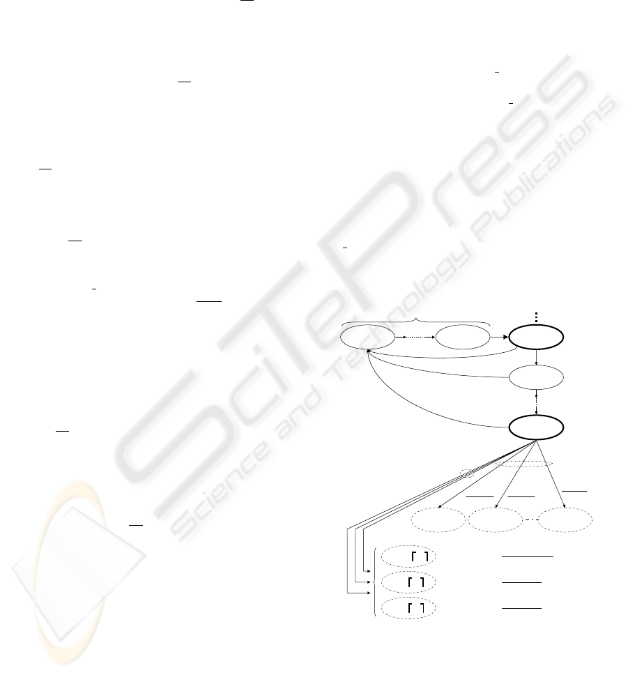
3.2.1 Pattern: Aifs Procedure and Outputs
The model is given in figure 2. The different states of
the pattern are self explanatory. We added to each
of the transitions from the output state ( j, −2, 1) a
Predicate/Transition type label. The predicate is the
value of the Backoff Counter (B
C[AC
i
]) that has been
randomly chosen at the beginning of the AIFS pro-
cedure (see section 2.2.1). If B
C[AC
i
] = 0, there
will be a transmission attempt at the end of the last
slot of AIFS if the medium is still idle, the trans-
mission attempt will either lead to a successful trans-
mission (state (−1, −1, ⌈T
s
⌉)) or to a collision (state
( j, −1, ⌈T
s
⌉) in case AC
i
loses a virtual collision and
AC
k
, winner of the virtual collision, transmits suc-
cessfully, or state ( j, −1,⌈T
c
⌉) in case AC
i
collides or
in case it loses a virtual collision and AC
k
collides).
If B
C[AC
i
] > 0, the chain transits into one of the
states [( j, 0, 0), ( j, 1, 0). . . ( j,W
j
− 1, 0)] representing
the beginning of the backoff procedure.
j,-2,1
j,-2,A-1
j,-2,Aj,-2, N+A
1
1-p
b
1-p
b
p
b
p
b
p
b
j,-2,A+1
11
1
j,1,0 j,W
j
-1,0j,0,0
1)(W
)p(1
j
b
+
−
1)(W
)p(1
j
b
+
−
1)(W
)p(1
j
b
+
−
B_C>0
B_C decrement
B_C=0 Tx attempt
with probability
with probability
with probability
1)(W
)p)(1p(1
j
ib
+
−−
1)(W
)pp(1
j
(2)
i
b
+
−
1)(W
)pp(1
j
(3)
i
b
+
−
j,-1, ªT
c
º
j,-1, ªT
s
º
-1,-1, ªT
s
º
Input State
(Start of
AIFS
Period)
Output
State
(Last slot
of AIFS)
Medium occupancy period
1-p
b
Figure 2: AIFS procedure pattern: 0 ≤ j ≤ m+ h.
3.2.2 Pattern: Backoff Procedure and Outputs
The model is given in figure 3. The input states of
the model are [( j, 0, 0), ( j, 1, 0). . . ( j,W
j
− 1, 0)]. The
transitions between these states represent the decre-
menting of the backoff counter while the medium is
REVISITING THE MARKOV CHAIN MODEL OF IEEE 802.11E EDCA AND INTRODUCING THE VIRTUAL
COLLISION PHENOMENON
79
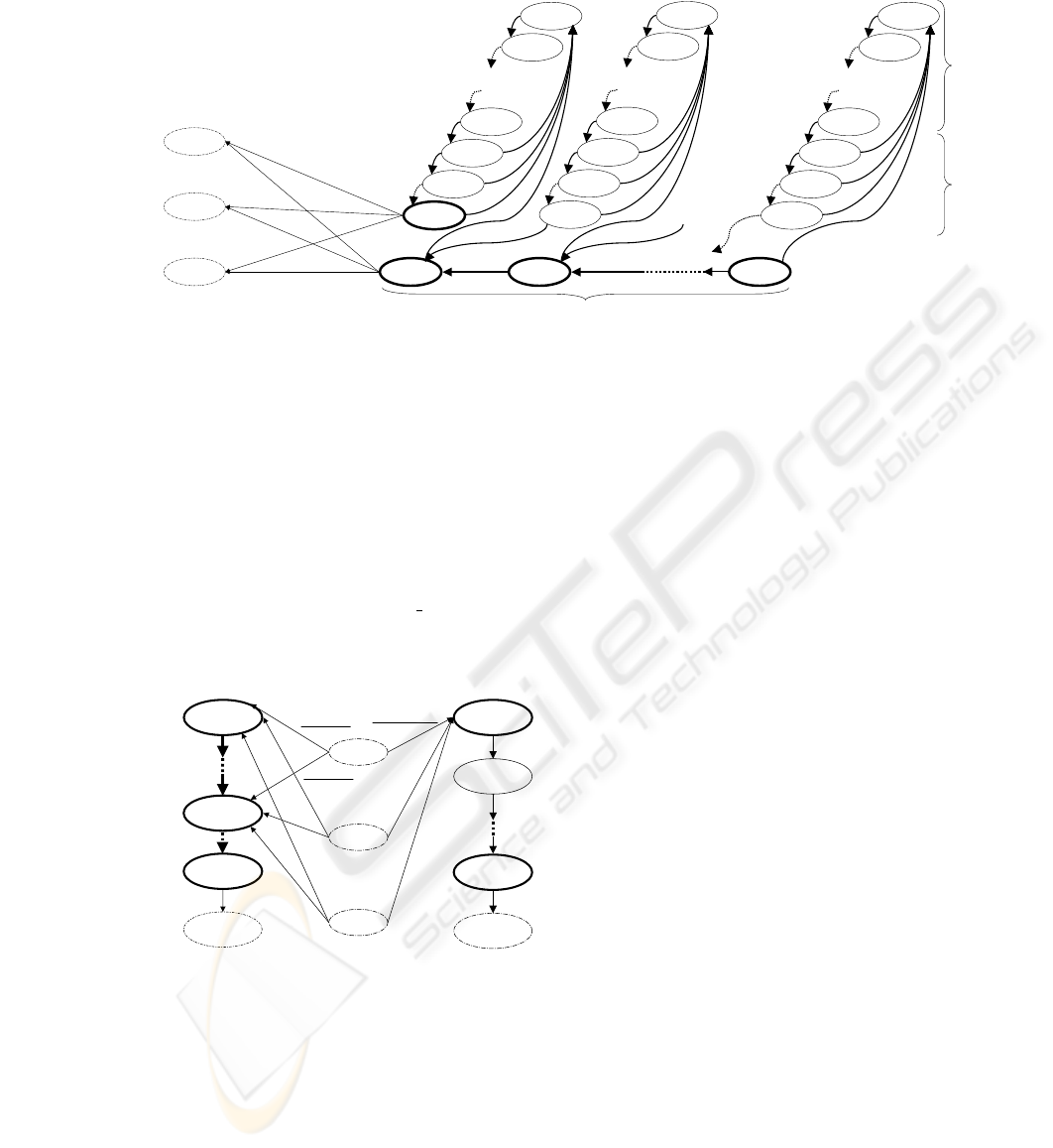
1-p
b
j,1,0 j,W
j
-1,0
1-p
b
1-p
b
j,1,N+A
j,1,N+A-1
j,1,A+1
j,1,A
j,1,A-1
j,1,1
j,W
j
-1,N+A
j, W
j
-1,N+A-1
j, W
j
-1,A+1
j, W
j
-1,A
j, W
j
-1,A-1
j, W
j
-1,1
1-p
b
1-p
b
1-p
b
1-p
b
1
1-p
b
1-p
b
1-p
b
1
1
1
1
1
1
1
p
b
p
b
p
b
p
b
p
b
p
b
p
b
p
b
j,0,N+A
j,0,N+A-1
j,0,A+1
j,0,A
j,0,A-1
j,0,1
1-p
b
1-p
b
1
1
1
1
j,0,0
-1,-1,
T
s
j,-1,
T
s
j,-1,
T
c
(2)
i
b
)pp(1−
(2)
i
b
)pp(1−
(3)
i
b
)pp(1−
(3)
i
b
)pp(1−
)p-)(1p(1
i
b
−
)p-)(1p(1
i
b
−
Input states from state (j,-2,1)
Decrementing of B_C
Output
states
Medium
occupancy
AIFS
p
b
p
b
p
b
Figure 3: Backoff Procedure pattern: 0 ≤ j ≤ m+ h.
idle (probability 1 − p
b
). If the medium goes busy
(probability p
b
), the decrementing will be frozen dur-
ing the medium occupancy and an AIFS period (rep-
resented by the subset of states above each counter
decrementing state). From the output states (( j, 0, 0)
or ( j, 0, 1)), a transmission is attempted if the medium
is idle. The transmission attempt will lead into one of
the states (−1, −1, ⌈T
s
⌉), ( j, −1, ⌈T
s
⌉), ( j, −1, ⌈T
c
⌉)
(as in section 3.2.1 - case where B
C[AC
i
] = 0).
3.2.3 Pattern: Actual Transmission Attempt
-1,-1, 1
-1,-1,
Ts
1
-1,-1,
Ts
-1
0,-2,A
1
1
1)(W
)p)(1p(1
j
ib
+
−
−
)p)(1p(1
i
b
−
−
)p)(1p(1
i
b
−
−
j,-2,1
j,0,1
j,0,0
j,-1,1
j,-1,
T
c
j,-1,
T
s
1
1
1
X,-2,A
X = j+1 if j<m+h
X = 0 if j=m+h
(3)
i
b
)pp(1−
(3)
i
b
)pp(1−
(2)
i
b
)pp(1−
(2)
i
b
)pp(1−
1)(W
)pp(1
j
(3)
i
b
+
−
1)(W
)pp(1
j
(2)
i
b
+
−
a) Collision
b) Successful
Transmission
Output
State
Output
State
Input
State
Input
State
Input
State
1
1
Figure 4: Outcomes of an actual transmission attempt:
0 ≤ j ≤ m+ h.
The model is given in figure 4. The states ( j, −2, 1),
( j, 0, 1) and ( j, 0, 0) are respectively the output states
in the model ”AIFS Procedure” for the first one and
”Backoff procedure” for the two others. Those are the
states leading to a transmission attempt and resulting
in either a successful transmission (right part of the
figure) or a collision (left part of the figure). In case
of a collision, two different entry states are possible
(both leading to state ( j, −1, 1) meaning two different
medium occupancy time):
• states ( j, −1, ⌈T
s
⌉) for a ⌈T
s
⌉ occupancy time in
case AC
i
lost a virtual collision and AC
k
, winner
of the virtual collision, successfully transmits;
• ( j, −1, ⌈T
c
⌉) for a ⌈T
c
⌉ occupancy time either in
case AC
i
accesses the medium and collides or in
case AC
i
loses a virtual collision and AC
k
, winner
of the virtual collision, collides.
Once the process is finished it will lead:
• in case of a successful transmission, a new packet
is taken into consideration, we thus go to its first
access attempt (state (0, −2, A));
• in case of a collision, if the retry threshold has not
been reached, the packet will go into a new trans-
mission attempt (state ( j + 1, −2, A)), if the retry
threshold has been reached, the packet is dropped
and a new packet is taken into consideration (state
(0, −2, A)).
3.3 Global Model
The global model is got by connecting the models of
the different ”Access Attempts” following the guide
of figure 1 (with j = 0, 1, 2. . . m, . . . m+ h).
4 CRITICISM OF KONG ET. AL.
MODEL
Several points of the behavior of an AC are not repre-
sented in Kong et. al.’s model (Kong et al., 2004):
• In Kong et. al.’s model, an AIFS period is con-
sidered only for the first transmission attempt (i.e.
before the backoff procedure of the first attempt).
However, EDCA stipulates also an AIFS period
WINSYS 2007 - International Conference on Wireless Information Networks and Systems
80

before the launch of every retransmission’s back-
off period. This is considered in our model with
pattern AIFS in figure 2 covering the first attempt
(j = 0) and the retransmissions ( j > 0).
• In EDCA, when the randomly chosen value of the
backoff counter is 0, a transmission can be at-
tempted, if the medium is idle, directly after the
last slot of AIFS. This is not represented in Kong
et. al.’s model. In figure 4, this aspect is mod-
elled by introducing the possibility of attempting
a transmission after the last slot of AIFS when the
backoff counter is zero (in states ( j, −2, 1) and
( j, 0, 1)) in addition to state ( j, 0, 0) considered by
Kong et. al..
• The virtual collision does not appear explicitly
in Kong et. al.’s model. This leads to erro-
neous representation of the collision (consider-
ing both types of collision as effective accesses
to the medium which is not true). By integrating
a correct representation of the virtual collision to
the model (figure 4), we achieve a more precise
model.
• Before attempting a medium access, an AC should
check for medium idleness, this is not represented
in Kong et. al.’s model. In our model, transmis-
sion attempts (from states ( j, −2, 1), ( j, 0, 1) and
( j, 0, 0)) are made with probability (1 − p
b
) i.e.
with a medium idle condition.
5 FUNDAMENTAL RELATIONS
FOR PERFORMANCE
ANALYSIS
5.1 Steady State Probability
Let b
j,k,d
be the steady state probability of state
( j, k, d) defined earlier in section 3.1. We derived for
each of the patterns described in section 3.2 a set of
equations expressing the steady state probabilities of
each state in terms of b
0,−2,1
. We chose this state be-
cause it is the first state from which an access may
be attempted. With those equations and the normal-
ization condition we obtain the expression of all the
probabilities in terms of m, h, A, ⌈T
s
⌉, ⌈T
c
⌉, N and W
j
which are known and , p
i
, p
(3)
i
and p
b
which will be
expressed in the following section. For lack of space
we only give the expression of b
0,−2,1
, all other steady
state probabilities can be easily found using classical
methods of steady state analysis. We have:
b
0,−2,1
=
⌈T
s
⌉(1− p
b
)(1− p
m+h+1
i
)
+p
i
⌈T
c
⌉(1− p
b
)
1−p
m+h+1
i
1−p
i
+p
(3)
i
(⌈T
s
⌉ − ⌈T
c
⌉)(1− p
b
)
1−p
m+h+1
i
1−p
i
+
1+Np
b
p
b
1−(1−p
b
)
A
(1−p
b
)
A−1
1−p
m+h+1
i
1−p
i
+
1+Np
b
2(1−p
b
)
A−1
∑
m+h
j=0
p
j
i
W
j
−1
This formula, if compared to Kong et. al.’s formula,
points out the main differences between both mod-
els: the single (1− p
b
) factor in the first three terms
of the sum indicates the idleness test before an ac-
cess is attempted; introducing an additional term to
the sum representing the different outcomes of a colli-
sion (third term of the sum);
1−p
m+h+1
i
1−p
i
factor (which in
fact is equivalent to
∑
m+h
j=0
p
j
i
) in the fourth term of the
sum corresponding to the AIFS arises from the fact
our model considers (as specified earlier) the AIFS
periods after a collision and so on.
5.2 Collision Probability and Busy
Probability
We give in the following sections the expressions of
the different probabilities used in the model. These
are essential for the use of the model for any per-
formance analysis. We differentiate three aspects of
the AC behavior: access attempt, actual access and
medium occupation. Unlike Kong et. al. we differ-
entiate an access attempt from an actual access, an
access attempt describes the possible contention be-
tween different ACs within a station. Thus an access
attempt followed by a lost virtual collision will not
result in an actual access.
5.2.1 Access Attempt
Let α
i
be the probability for AC
i
to attempt a trans-
mission in a randomly chosen time slot. α
i
can thus
be written:
α
i
= (1− p
b
)
m+h
∑
j=0
1
W
j
+ 1
b
j,−2,1
+ b
j,0,1
+ b
j,0,0
The virtual collision probabilities can be written:
•
p
v
i
=
∏
x∈[0..3]x6=i
(1− α
x
)
• p
lv
i
= 0 if i = 0
• p
lv
i
= 1−
∏
x<i
(1− α
x
) otherwise
• p
wv
i
= 1− (p
lv
i
+
p
v
i
)
REVISITING THE MARKOV CHAIN MODEL OF IEEE 802.11E EDCA AND INTRODUCING THE VIRTUAL
COLLISION PHENOMENON
81

5.2.2 Actual Access
We define τ
i
(respectively τ) as the probability for AC
i
(respectively a station of the network) to effectively
access the medium at a randomly chosen time. We
have:
τ
i
= (
p
v
i
+ p
wv
i
)α
i
and τ =
∑
i=3
i=0
τ
i
Thus we may define p
r
i
(the real collision probability
of AC
i
) as the probability for at least two stations to
access the medium in a randomly chosen time slot:
p
r
i
= 1− (1− τ)
M−1
(M being the number of stations
in the network), the same applies to the value of p
r
k
.
These definitions allow us to write p
i
, p
(2)
i
and p
(3)
i
defined in section 3.1.
5.2.3 Medium Occupation
In order to define the busy probability, we define υ
i
(respectively υ) as the probability that the channel is
occupied by a given AC
i
(respectively a station) in a
given time slot. υ
i
can in fact be understood as the
probability for the Markov chain to be in one of the
states where an access is ongoing (a successful trans-
mission or a real collision of AC
i
). We thus have:
υ
i
=
⌈T
s
⌉
∑
d=1
b
−1,−1,d
+
(
p
v
i
+ p
wv
i
)p
r
i
p
(2)
i
+ p
(3)
i
m+h
∑
j=0
⌈T
c
⌉
∑
d=1
b
j,−1,d
and υ =
∑
i=3
i=0
υ
i
. The channel busy probability p
b
can thus be expressed as the probability that at least
one station occupies the medium (complementary of
the probability that no station occupies the medium):
p
b
= 1− (1− υ)
M
.
5.3 Throughput
Let S be the normalized throughput as defined by
Bianchi (Bianchi, 2000): S is the ratio of time the
channel is used to transmit payload bits. Further on
we define s
i
, the normalized throughput of AC
i
as the
ratio of time the channel is used to transmit payload
bits corresponding to an AC
i
of a station, and S
i
as the
normalized throughput of all AC
i
s of the same priority
in the network. We use for the throughput calculation
the formula described by Kong et. al. in (Kong et al.,
2004).
S
i
=
p
si
E[P]
E[I]+
∑
3
i
′
=0
p
si
′
(T
s
+AIFS[AC
i
′
])+(1−
∑
3
i
′
=0
p
si
′
)T
c
with E[P] being the mean payload transmission time
in slot times, E[I] the mean idle period obtained as
E[I] =
1
p
b
− 1 and p
si
the conditional transmission
probability:
p
si
=
M((1−υ)
(M−1)
)(
∏
i
′
>i
(1−υ
i
′
))(
∑
⌈T
s
⌉
d=1
b
−1,−1,d
)
1−(1−υ)
M
Table 1: Details of variables used for simulation.
Variable Value
M (number of stations) 2..9
Payload size 1000 bytes
⌈T
s
⌉ 55
⌈T
C
⌉ 14
AIFS AC VO 2
AIFS AC VI 2
AIFS AC BE 3
CW range AC VO 3..7
CW range AC VI 3..15
CW range AC BE 15..1023
Retry Limit 4
6 MODEL VALIDATION
The Markov Chain presented in section 3 represents
the behavior of an AC
i
in a local context, that of the
station the AC
i
is in; and a global context, that of the
different stations in the network. These contexts are
integrated to the model using a number of parameters:
the different collisions probabilities p
i
(2) and p
i
(3)
and the busy probability p
b
. Two different uses of the
model are investigated hereafter:
• as a formula based model: using the formulas pre-
sented in sections 5.2 to represent the contexts in
which evolves AC
i
.
• as a measurement based model, replacing the
above mentioned formulas with measures of the
state of both the network and the local context.
In order to confirm the behavior of the model, a set
of simulations was carried out. We detail in the fol-
lowing section the simulation set, we then measure up
the results given by the model in both its use cases to
the results obtained by simulation (from a throughput
point of view).
6.1 Simulation Set
M EDCA enabled stations share a medium. The sta-
tions’ physical bit rate is set to 11 Mbps. In each
station the categories AC
VO, AC VI and AC BE
of each station are saturated with 1000 byte payload
packets. RTS-CTS handshake is enabled. The techni-
cal details of the simulations (used also for the model
based performance analysis) are given in table 1.
6.2 Formula based Use of the Model
The model validation undertook by Kong et. al.
shows a good performance of their model. The prob-
lem is that Kong et. al.’s simulation covers only
stations where the only active access categories are
WINSYS 2007 - International Conference on Wireless Information Networks and Systems
82
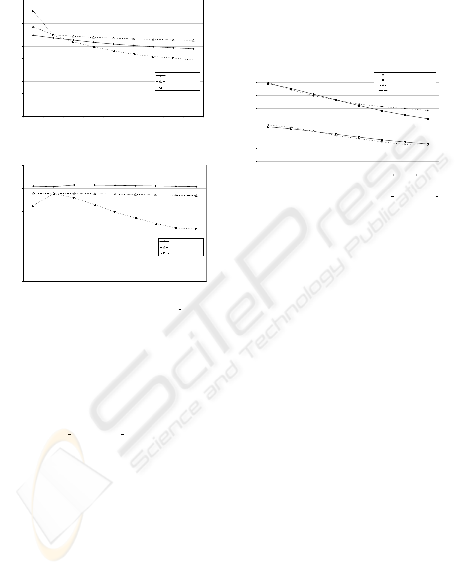
0
0.05
0.1
0.15
0.2
0.25
0.3
0.35
0.4
0.45
0.5
1 2 3 4 5 6 7 8 9
Stations
Normalized Throughput
Kong et. al.
Enhanced Model
Simulation
Figure 5: Comparing the Throughput of AC VO.
0
0.05
0.1
0.15
0.2
0.25
1 2 3 4 5 6 7 8 9
Stations
Normalized Throughput
Kong et. al.
Enhanced Model
Simulation
Figure 6: Comparing the Throughput of AC VI.
AC VO and AC BE, and with contention windows re-
ducing the probability of virtual collision. The aim
of this set of simulation is to compare the behavior
of the enhanced model towards Kong et. al.’s model
and simulation in scenarios where the stations have
their three top priority access categories active using
the default contention window ranges. Figure 5 and
6 show a comparison between the calculated through-
puts of both AC
VO and AC VI using both models
and the results of simulations presented in previous
section. Two main conclusions can be drawn from
the graphs:
• first, both models give merely good results in
cases with a low number of station, but are outper-
formed with a higher number of station (M > 3),
this is due to a lack of exactitude of the real colli-
sion representation.
• In a low number of station case, the enhanced
model’s results are closer to the simulation re-
sults than Kong et. al. model’s results. In a high
number of station case, the effects of our enhance-
ments are hidden by the real collision lack of ex-
actitude.
In the following section, this issue is solved by deriv-
ing the real collision probability from measurements
in order to give a better view of the global context.
6.3 Measurement based Use of the
Model
0
0.05
0.1
0.15
0.2
0.25
0.3
0.35
0.4
2 3 4 5 6 7 8 9
Stations
Normalized Throughput
AC_VO Simulation
AC_VO Enhanced Model
AC_VI Simulation
AC_VI Enhanced Model
Figure 7: Comparing the Throughput of AC VO and AC VI
with probability insertion.
A set of calculations were made using the model in-
serting into it the mean real collision probability as
recovered from the simulation (this being the ratio
between total collisions and total access attempts).
Figure 7 shows the throughputs as calculated by the
model and the simulation. We can see that the results
given by the model give a close view of the through-
put achieved by each access category (as recovered
from simulation results) even with a high number of
station.
7 CONCLUSION
The paper presented a new Markov chain model of
IEEE 802.11e EDCA. Its main contribution is it in-
herently represents the virtual collision phenomenon
which was not precisely considered in previous mod-
els. In addition, the model corrects several backoff
scheme related misconceptions of previous models.
This made us introduce the concept of access attempt
and differentiate it from an actual access. We claim
this model to be an exhaustive model of the behav-
ior of EDCA with respect to an access category in the
saturation regime.
The model has been numerically solved and validated
against simulation. It has shown to particularly fit
the simulation when some of its parameters (collision
probability, ..) are derived (typically by measurement)
from network load. We believe that this is the best use
of our model which can for instance find its applica-
tion in the context of admission control for QoS sup-
port. More precisely, an access point could use our
model to assess the maximum throughput that can be
offered to one of its access categories by injecting into
REVISITING THE MARKOV CHAIN MODEL OF IEEE 802.11E EDCA AND INTRODUCING THE VIRTUAL
COLLISION PHENOMENON
83

the model the collision probability observed on the
medium. This is particularly one of our future direc-
tions in addition to reducing the model using Beizer
rules (Beizer, 1971).
REFERENCES
802.11e (2005). IEEE Standard for Telecommunica-
tions and Information Exchange between Systems –
LAN/MAN specific Requirements – Part 11: Wireless
LAN MAC and PHY specifications – Amendment 8:
Medium Access Control QoS Enhancements.
Beizer, B. (1971). he architecture and Engineering of Dig-
ital Computer Complexes. Plenum Press, New York.
Bianchi, G. (2000). Performance analysis of ieee 802.11
distributed coordination function. IEEE Journal on
selected areas in communications, 18(3):535–547.
Kong, Z., Tsang, D. H. K., Bensaou, B., and Gao, D. (2004).
Performance analysis of ieee 802.11e contention-
based channel access. IEEE Journal on selected areas
in communications, 22(10):2095–2106.
Mangold, S., Choi, S., Hiertz, G. R., Klein, O., and Walke,
B. (2003). Analysis of ieee 802.11e for qos sup-
port in wireless lans. IEEE Wireless Communications,
10(6):40–50.
Wu, H., Wang, X., Zhang, Q., and Shen, X. (2006). Ieee
802.11e enhanced distributed channel access (edca)
throughput analysis. IEEE International Conference
on Communications, 1:223–228.
Zhu, H. and Chlamtac, I. (2005). Performance analysis for
ieee 802.11e edcf service differentiation. IEEE Trans-
actions on wireless Communications, 4(4):1779–
1788.
WINSYS 2007 - International Conference on Wireless Information Networks and Systems
84
